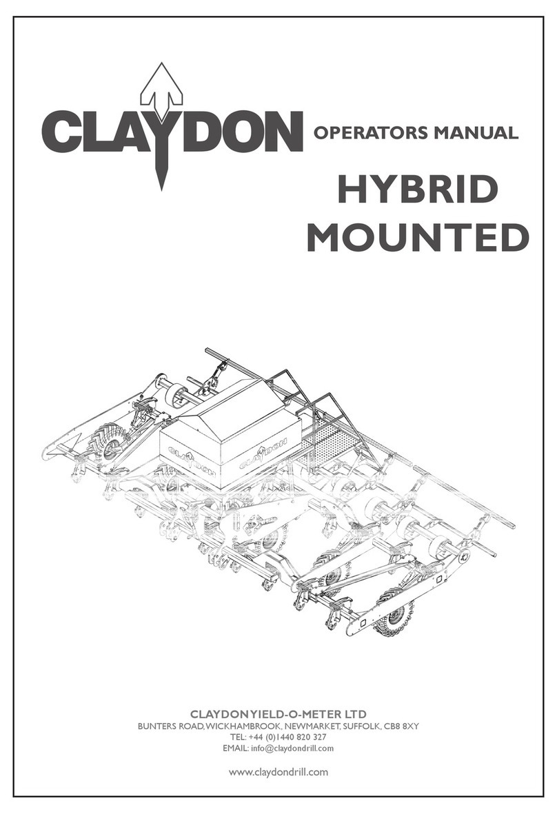
Claydon 15m Straw Harrow User manual

OPERATORS
MANUAL
CLAYDONYIELD-O-METER LTD
BUNTERS ROAD,WICKHAMBROOK, NEWMARKET, SUFFOLK, CB8 8XY
TEL: +44 (0)1440 820 327
EMAIL: info@claydondrill.com
www.claydondrill.com
9M
STRAW
HARROW
DOC0132 REV-00
Authorised Representative

CLAYDONYIELD-O-METER LTD
BUNTERS ROAD,WICKHAMBROOK, NEWMARKET, SUFFOLK, CB8 8XY
TEL: +44 (0)1440 820 327
EMAIL: info@claydondrill.com
www.claydondrill.com
DOC0132
REV-00
©

3OPERATORS MANUAL - 9M STRAW HARROW
CONTENTS
WARRANTY REGISTRATION
DECLARATION OF CONFORMITY
IDENTIFICATION OF MACHINE
INTRODUCTION
SAFETY
DIRECTIVE PROVISIONS
PRE-WORK PREPARATION
IN FIELD OPERATION
CARE AND MAINTENANCE
PARTS MANUAL
PARTS MANUAL INDEX
A
B
C
D
E
F
G
H
I
J
K


In order to activate your Claydon Warranty this page & the Warranty check sheet and
conformation form must be completed and returned to:
Service Department
Claydon Yield-O-Meter Ltd
Bunters Road,
Wickhambrook,
Newmarket,
Suffolk,
CB8 8XY
•The Machine is washed off upon delivery to remove any road salt.
•The drills hydraulic free ow service is plugged in prior to the drill being operated.
•The drills case drain is correctly installed onto the tractor if applicable.
CUSTOMER NAME:
CUSTOMER
SIGNATURE:
TELEPHONE NUMBER:
MACHINE SERIAL
NUMBER:
DATE OF
COMMISSIONING:
ADDRESS:
RETURN REGISTRATION DOCUMENT SOYOUR MACHINE IS REGISTERED IF NOT ALL
WARRANTY CLAIMS WILL BE REJECTED.
Your Claydon product warranty cover will start 12 months from the installation date.
Receive updates about your product including safety updates.
Download your documents.
Get support.
Alternatively email completed documents to: service@claydondrill.com
COUNTY: COUNTRY:
POST CODE:
DATE:
WARRANTY
REGISTRATION CARD
PLEASE ENSURE


This form must be completed along with the Warranty Registration Card on the commissioning of a new
Claydon machine in order to activate its warranty cover. It is the dealers obligation to ensure that the
Warranty registration document is completed & the end user has signed it and the document is sent to
Claydon. In the event of a dealer not being present it is the customers responsibility to return this form to
the following address.
SUPPLYING DEALER NAME
MACHINE SERIAL NUMBER
COUNTY COUNTRY POST CODE
ADDRESS
TELEPHONE NUMBER
DATE OF COMMISSIONING
I ...................................................(Representative Name)
have on behalf of ..............................................................
(Dealer Name) commissioned the machine above
to the best of my ability and have covered all the
points in this check as a minimum.
Signed.......................................................................
Date
I …………………………………………(end user
name) have received the commissioning of my
machine from a qualied Claydon representative
and am happy with the competence of the
representative and the level of service I have
received.All the details on this form are correct to
the best of my knowledge.
Signed.......................................................................
Date
DD/MM/YYYY
TASK COMPLETED
The customer (and any operator of the machine) has been issued and read the operators manual.
Customer is aware of all transport locks on the machine and knows how to operate them correctly.
The customer understands the correct sequence for folding and unfolding the machine.
The customer understands how to set the machine level (front to rear).
The customer understands how to set the machine level (left to right).
The customer understands how to adjust and set the operating height of the machine.
The customer understands how to adjust and set the operating angle of the tines.
The customer knows all the lubrication/maintenance points on the machine.
DD MM YYYY DD MM YYYY
WARRANTY COMMISSIONING
CHECK SHEET &
CONFORMATION FORM
Your Claydon product warranty cover will start 12 months from the installation date.
Service Department, Claydon Yield-O-Meter Ltd, Bunters Road,Wickhambrook, Newmarket, Suffolk,
CB8 8XY. Alternatively email completed documents to: service@claydondrill.com
CUSTOMER NAME


9
B
DECLARATION OF CONFORMITY
OPERATORS MANUAL - 9M STRAW HARROW
EC Declaration of Conformity
In accordance with EN ISO 17050-1:2004
We: Claydon Yieldometer Ltd
of: Gaines Hall
in accordance with the following Directive(s):
2006/42/EC
The Machinery Directive
Hereby declare that Equipment: Claydon Drills
Model number: Straw Harrow
Serial Number:
is in conformity with the applicable requirements of the following documents
I hereby declare that the equipment named above has been designed to comply with the relevant sections of the above referenced
specications and is in accordance with the requirements of the Directive(s)
Oliver Claydon
Director of Operations
Done at
Gaines Hall
Wickhambrook
On: 07/03/2016
The technical documentation for the machinery is available from:
Claydon Yieldometer Ltd
Bunters Road
Wickhambrook
Newmarket, Suffolk, CB8 8XY
Ref. No.
EN ISO 12100-1:2003
EN ISO 12100-2:2003
Title
Safety of Machinery - Basic Concepts
Safety of Machinery - Basic Concepts
Edition / Date
2003
2003
SH0001 - SH****

10 OPERATORS MANUAL - 9M STRAW HARROW
CIDENTIFICATION OF MACHINE
Identication Plate
Mass Min/Max - Maximum/Minimum laden mass of the vehicle in ‘Kg’
Model - Machine information
Serial No - Serial number of machine
Year -Year of manufacture
Claydon Yeildmeter Ltd
Gaines Hall, Wickhambrook
Newmarket, Suolk,
CB8 8YA, England
+44 (0)1440 820327
www.claydondrill.com
Model:
Serial No:
Year:
Mass Min/Max:
MSH9
MSH9000
2021
1500/2000

11OPERATORS MANUAL - 9M STRAW HARROW
C
IDENTIFICATION OF MACHINE
MACHINE WORKING
WIDTH
TRANSPORT
WIDTH
WEIGHT
(APPROX)
NUMBER OF HARROW
TINES
HORSE POWER
REQUIREMENTS
(ESTIMATED)
9M 9M 3M 2100KG 75 175HP
When ordering spare parts always
quote:
- Model
- Serial No.
- Year of manufacture
- Part numbers of required parts
(located in parts book)
- Account Name
Record your serial number here: …………………………………………………………………
TECHNICAL DATA
Identication of Machine
Data plate location
Please ensure separate warranty registration card is lled in upon purchase of your machine to validate
warranty claims.This is located at the rear of the operators manual.
You may need to quote the serial number of your machine when you order spare parts in the future.
WARRANTY REGISTRATION
SPARE PARTS ORDERING PROCEDURE
VIN number location

DINTRODUCTION
12 OPERATORS MANUAL - 9M STRAW HARROW
Thank you for your purchase of a new Straw Harrow.
The purpose of this Operator’s Manual is to explain to the operator how to set up, use and maintain the
machine.
It is important that the operator reads this manual carefully to correctly set up, use and maintain the machine
safely.
For any further assistance or explanation on the use and maintenance of your machine, please contact your
supplying dealer or alternatively ClaydonYield-O-Meter Ltd using the contact details given on the front cover.
The Claydon Straw Harrow will give many years of excellent service with little maintenance due to its robust
construction and its small number of moving parts. However, regular routine maintenance will give you the
optimum efciency and working machine life of your machine.
In the interest of product development Claydon may (at their discretion) issue updates or component changes
which may improve your machines performance or longevity.
9M STRAW
HARROW

13
D
INTRODUCTION
OPERATORS MANUAL - 9M STRAW HARROW
Safety decals can be found located on your machine in numerous locations, these decals must be observed to
ensure your safety and that the machine is operated in a safe manner.
If any of the decals become illegible or damaged, new decals can be ordered and attached in the appropriate
position.The decals must not be removed.
Decal Locations

ESAFETY
14 OPERATORS MANUAL - 9M STRAW HARROW
Decal Locations

15
E
SAFETY
OPERATORS MANUAL - 9M STRAW HARROW
DECAL MEANING
Read the operating manual carefully.
Prior to operating the machine the manual must be read fully and
understood.
Do not stand between the tractor and the machine.
Standing between tractor and the drill is especially prohibited
during coupling and uncoupling.
Remove the key before servicing.
Before any repairs or servicing turn off the engine and take out
the key.
Riding on the machine is prohibited.
Serious or fatal injury can occur as a result of riding on the
machine.
Proceed with care in the event of leaking hydraulic
uid.
Defective hydraulic hoses or incorrectly seated hydraulic
couplings can trigger unpredictable machine movements. High
pressure uid can puncture skin causing serious injury or death.
Keep clear of slewing range.
There is an extreme risk of injury or death from slewing or
folding machine parts.
Decal Meanings
DC0026
DC0034
DC0027
DC0036
DC0037
DC0039

ESAFETY
16 OPERATORS MANUAL - 9M STRAW HARROW
DECAL MEANING
Risk of crushing.
Gaps between components may become smaller or
disappear completely.
Re-tighten all nuts and bolts.
All nuts should be checked and re-tightened after a few
operating hours. Nuts may come loose due to machine
vibration.
Avoid overhead cables.
Hydraulic connections.
Hydraulic connections overview.
Decal Meanings
DC0029
DC0035
DC0038
DC0122

17
E
SAFETY
OPERATORS MANUAL - 9M STRAW HARROW
Machine Overview
The terms ‘front’ ‘rear’ ‘left’ and ‘right’ in this manual refer to the machine as follows:
‘Front’ indicates the 3 point linkage end of the machine
‘Rear’ indicates the machine end when viewed from the rear
‘Left’ indicates the left of the machine as you look at the machine from the rear
‘Right’ indicates the right of the machine as you look at the machine from the rear.
Front
Rear
Left
Right

FDIRECTIVE PROVISIONS
18 OPERATORS MANUAL - 9M STRAW HARROW
1. Manual holder
2. Electronic junction box
3. Machine folding ram
4. Harrow tines
5. Harrow tine folding ram
6. Rear lights
Machine Overview
1.
4.
3.
6.
5.
2.

19
F
DIRECTIVE PROVISIONS
OPERATORS MANUAL - 9M STRAW HARROW
Directive Provisions
This Claydon Straw Harrow conforms to Machinery Directive 2006/42/EC (see Declaration of Conformity
at the front of the manual).
AIRBORNE NOISE EMISSIONS
N/A
WARNING AND CAUTION
These warnings and cautions must be observed when operating the Straw Harrow
• Ensure total weight of tractor/machine combination does not exceed permitted limits and weight of tractor
is sufcient for safe eld and road use.
• Do not allow anyone to stand between tractor and machine during coupling/uncoupling procedures.
• For maintenance/adjustment of the machine ensure that it is lowered to the ground on the 3 point linkage.
• The hydraulic system on the machine operates under high pressure. Pressurised hydraulic oil is dangerous
so connecting/disconnecting the machine must only be undertaken with the tractor engine turned off and the
pressure in the hoses released.
• Before operating the machine ensure no-one is standing within range of its turning circle
Directive Provisions
!
WARNING SYMBOLS
Warning - Always pay extra attention to any text next to this symbol.This symbol could
relate to something which can cause damage to the machine, serious injury or death. Please
take the relevant precautions to avoid dangerous situations.
Eye Protection is required - In the interest of safety, eye protection must be worn.
Gloves are required - In the interest of safety, gloves must be worn.
!Please Note - Information relating to this symbol may be worth noting as a useful tip to
help use the machine more effectively.

GPRE-WORK PREPARATION
20 OPERATORS MANUAL - 9M STRAW HARROW
The Claydon Straw Harrow can be mounted onto any compatible three point linkage with the linkage pins
supplied and CATIII balls (not supplied).
Once the Straw Harrow is attached and at the correct working depth, the top link should be set at an angle
in which the convergence point between the upper and lower link arms should fall at the front axle.This
can be achieved by altering the top link pin attachment points on the tractor and machine.This ensures
stability and the mass of the implement is used correctly.
To connect the Straw Harrow:
1. Connect the 7 pin connection plug (5) to the 7 pin socket at the rear of the tractor using a safe route so
the cable can’t be caught or snagged.
2. Connect the fold and unfold 1/2” ISO connectors (1,2, 3 & 4) to the tractor.
Connecting Straw Harrow to the Tractor
1. Upper link point
2. Upper hitch point
3. Lower link point
4. Lower hitch point
5. Vertical virtual hitch point
1. Straw Harrow increased tine aggression
2. Straw Harrow decreased tine aggression
3. Straw Harrow fold connection
4. Straw Harrow unfold connection
5. 7 pin connection plug
1. 2.
3. 4.
5.
HYDRAULIC & ELECTRICAL CONNECTIONS
4.
3.
2.
1.
5.
Other manuals for 15m Straw Harrow
2
Table of contents
Other Claydon Farm Equipment manuals
Claydon
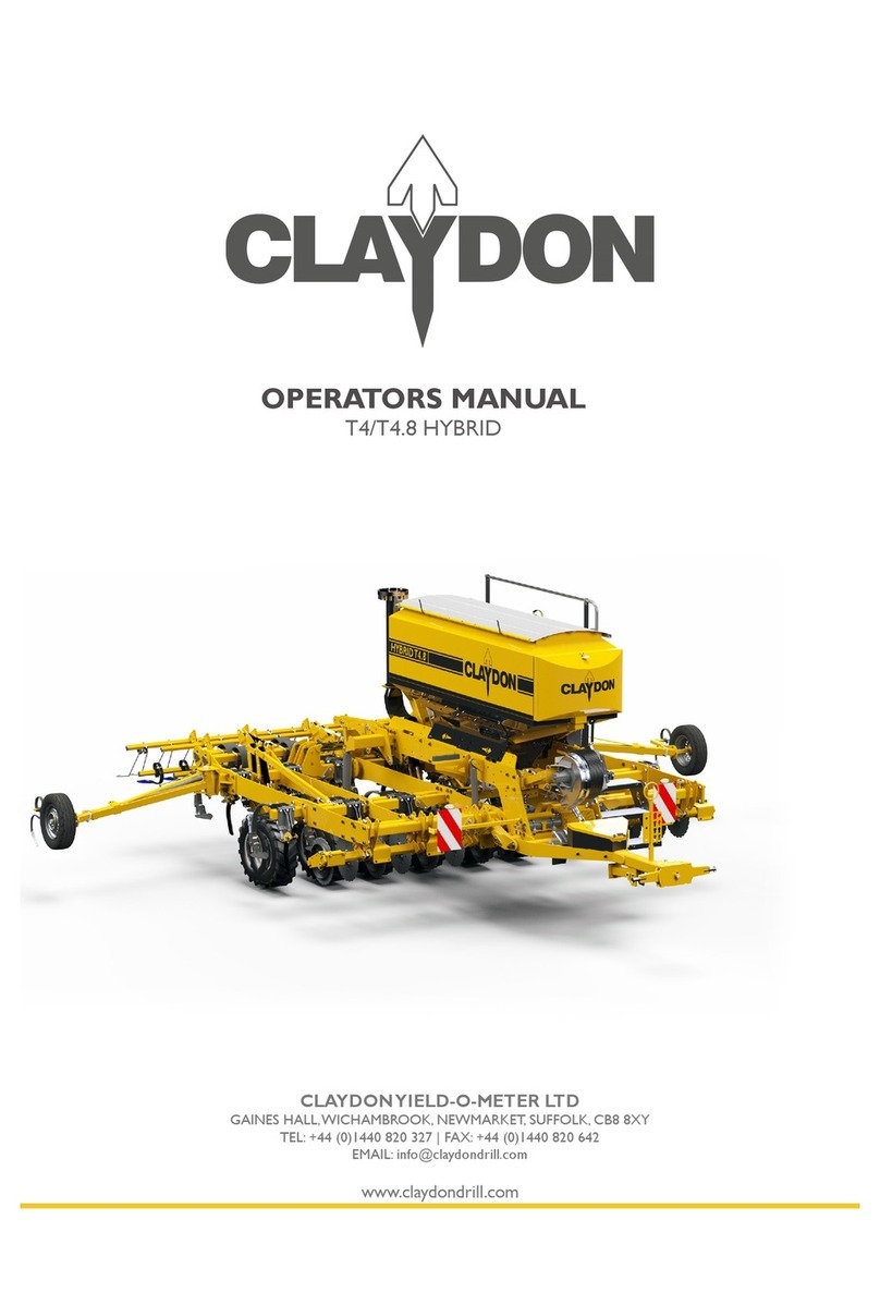
Claydon HYBRID T4 User manual
Claydon
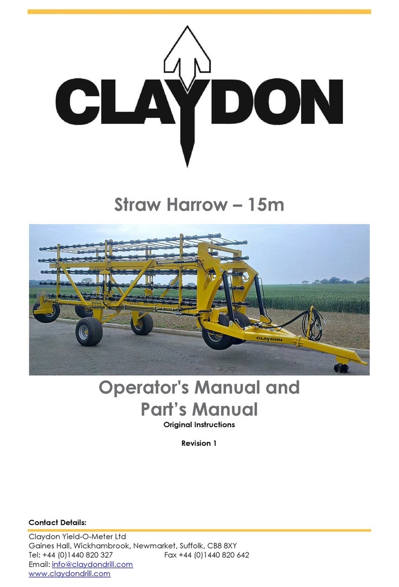
Claydon 15m Straw Harrow User manual
Claydon
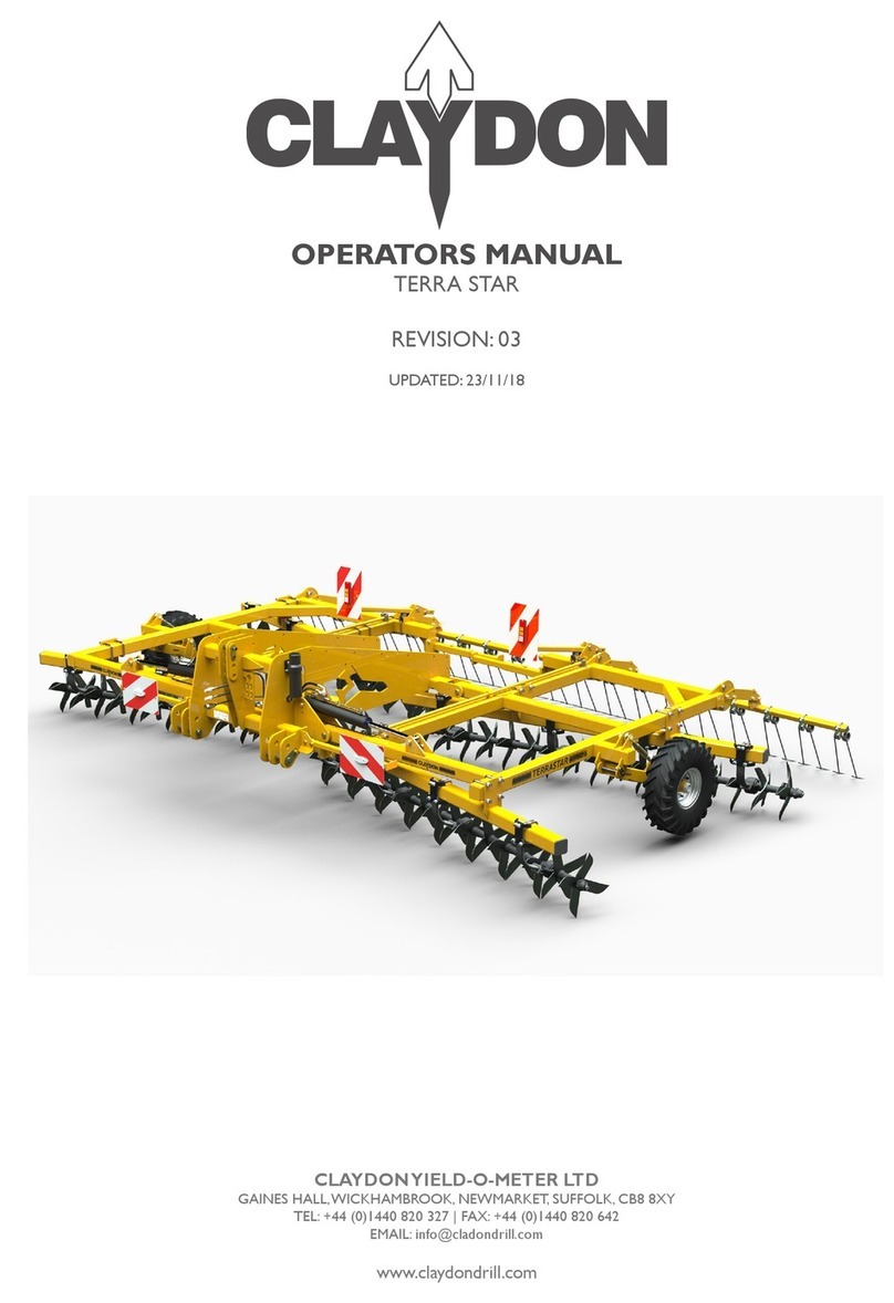
Claydon TERRA STAR User manual
Claydon
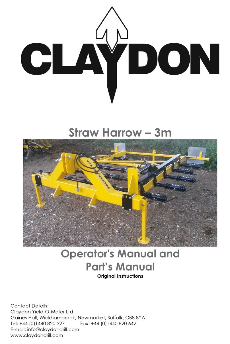
Claydon 15m Straw Harrow User manual

Claydon
Claydon Hybrid Front Hopper User manual
Claydon
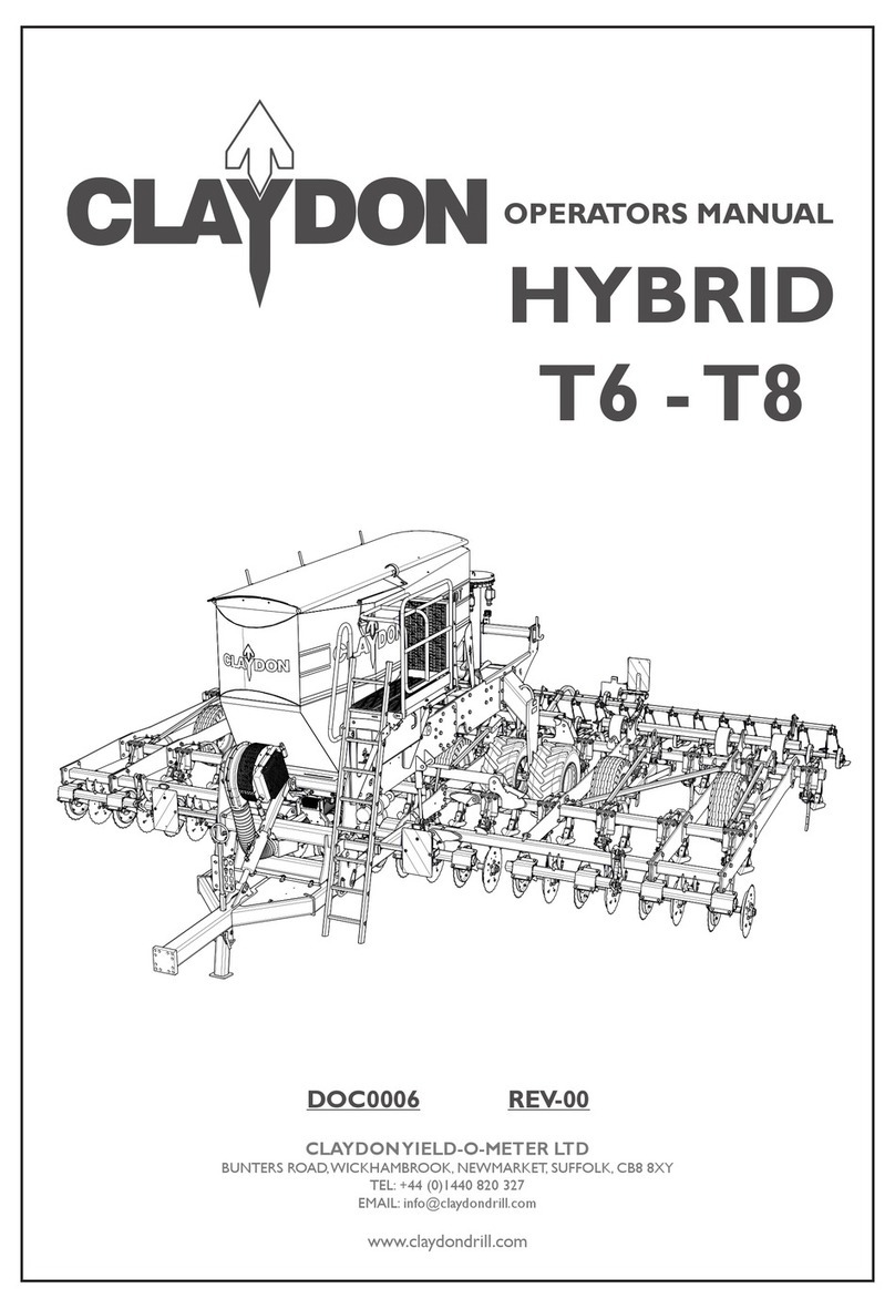
Claydon HYBRID T6 User manual
Claydon
Claydon HYBRID M3 User manual
Claydon
Claydon TERRABLADE User manual
Claydon
Claydon HYBRID M3F User manual
Claydon
Claydon TERRASTAR Programming manual
