Claydon 15m Straw Harrow User manual

15m Straw Harrow
Contents
1.0 Straw Harrow Warranty Registration........................................................................... 1
2.0 Safety............................................................................................................................. 3
2.1 Warning Symbols ........................................................................................................3
3.0 Introduction................................................................................................................... 5
3.1 Identification of the Machine........................................................................................5
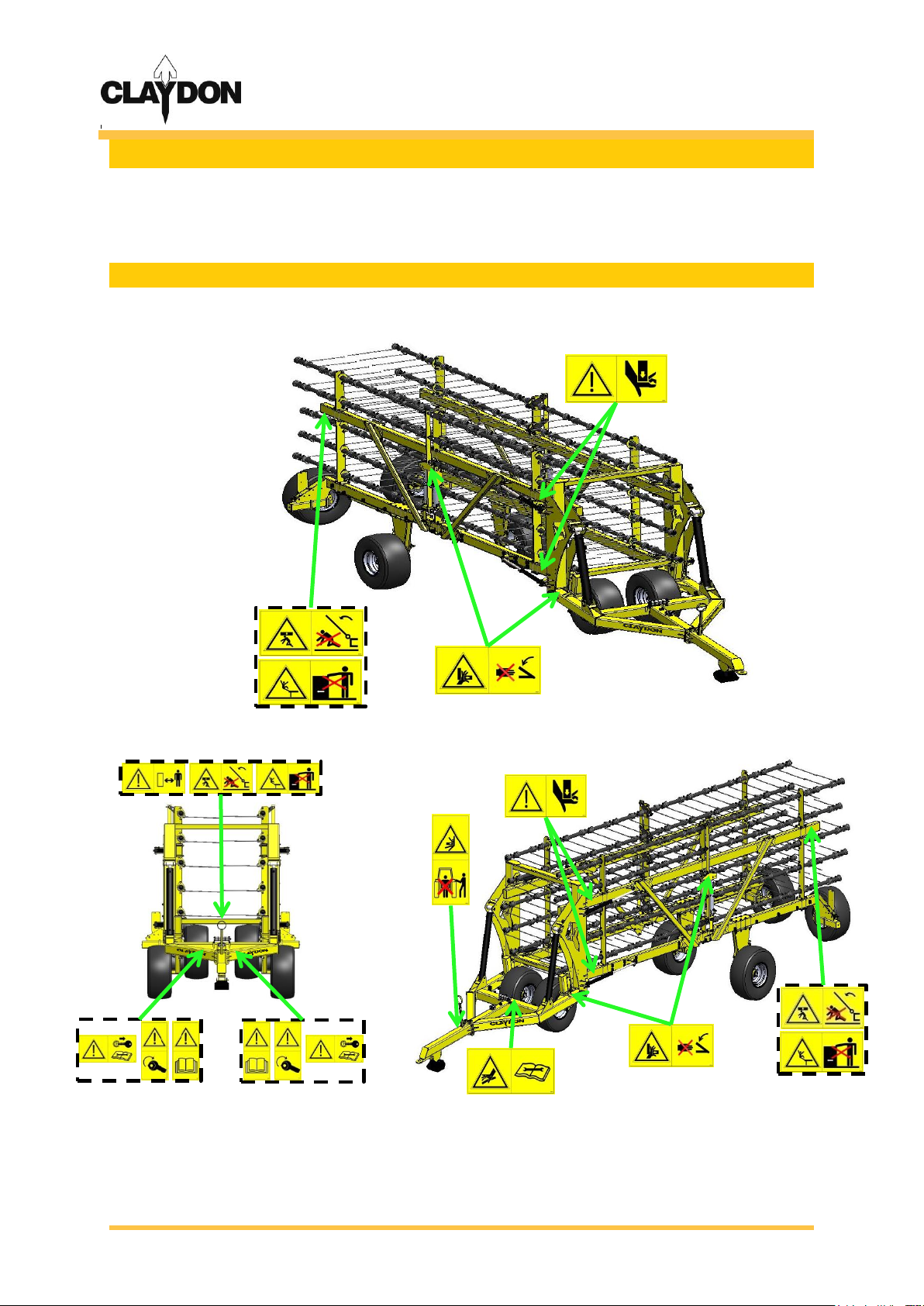
3.2 Warnings and Cautions ...............................................................................................6
4.0 Equipment Overview..................................................................................................... 6
5.0 Connecting the Straw Harrow to the Tractor............................................................... 7
6.0 Field use ........................................................................................................................ 9
6.1 Working Height..........................................................................................................10
7.0 Care and Maintenance ................................................................................................ 13
7.1. Tyre Pressures.........................................................................................................13
7.2 Lubricating Points......................................................................................................13
Appendix A –Straw Harrow Specifications .................................................................... 15
Appendix B –Declaration of Conformity......................................................................... 16
Part's Manual
15m Straw Harrow Parts Manual...................................................................................... 17
Pole Assembly .................................................................................................................. 18
Centre Chassis Assembly ................................................................................................ 19
Harrow Wing Assembly - RH............................................................................................ 21
Harrow Wing Assembly - LH ............................................................................................ 23
Scharmüller Hitch –Optional Extra ................................................................................. 25
Stand.................................................................................................................................. 26
Hydraulics –Rake Angle Circuit...................................................................................... 27
Hydraulics –Depth Control Circuit.................................................................................. 28

15m Straw Harrow
[1]
1.0 Straw Harrow Warranty Registration
In order to activate your Claydon Warranty this page must be completed and returned to:
Claydon Yield-O-Meter Ltd
Gaines Hall,
Wickhambrook,
Newmarket,
Suffolk,
CB8 8YA
Tel: +44 (0) 1440 820 327
Fax: +44 (0) 1440 820 642
IF THE REGISTRATION DOCUMENT IS NOT RETURNED THEN THE STRAW HARROW
WARRANTY WILL BE VOID
Straw Harrow Warranty Registration
NAME:
ADDRESS:
CONTACT NUMBER:
DELIVERY DATE:
SERIAL NUMBER:
PLEASE ENSURE:
The Machine is washed off upon delivery to remove any road salt.
SIGNATURE:
THE HYDRAULIC FREE FLOW SERVICE MUST BE PL THE HYDRAULIC FREE
FLOW SERVICE MUST BE PLUGGED IN PRIOR TO THE DRILL BEING
OPERATED.UGGED IN PRIOR TO THE DRILL BEING OPERATED.

15m Straw Harrow
[2]
Commissioning Check Sheet and Conformation Form –15 Straw Harrow
All points in this form must be completed on the commissioning of a new Claydon machine with the
end user. This form along with a filled in Warranty Card (located in the instruction manual) must be, fully
completed, signed by the customer and returned to: The Service Department, Claydon Yield-O-Meter
Ltd, Gaines Hall, Wickhambrook, Newmarket, Suffolk, CB8 8YA within 7 days of the commissioning of the
machine for Warranty to be valid. It is the customer’s responsibility to return these forms.
Customer Name:……………………….………………………............ Telephone Number:……………………………..
Machine serial number:………………….………………………………. Date of commissioning:……………………..
Address:…………………………………………………………………………...……………………………………………….
County:…………………………………..Country:………………………………………Postcode:…………………………
Task
Completed
The customer (and any operator of the machine) has been issued with and read the
operators manual.
Customer is aware of all transport locks on the machine and knows how to operate
them correctly.
The customer understands the correct sequence for folding and unfolding the
machine.
The customer understands how to set the machine level (front to rear).
The customer understands how to set the machine level (left to right).
The customer understands how to adjust and set the operating height of the
machine.
The customer understands how to adjust and set the operating angle of the tines.
The customer knows all the lubrication/maintenance points on the machine.
I …………………………………………. (representative name)
on behalf of ……………………………………….(dealer
name) have commissioned the machine above to the
best of my ability and have covered all the points in this
document as a minimum.
Signed………………………………………………..
Date…………………………..
I …………………………………………(end user name) have
received the commissioning of my machine from a
qualified Claydon representative and am happy with the
competence of the representative and the level of
service I have received. All the details on this form are
correct to the best of my knowledge.
Signed…………………………………………………
Date…………………………..

15m Straw Harrow
[3]
2.0 Safety
Safety stickers can be found located on your Claydon Straw Harrow at numerous locations
(Figure 1), these stickers must be observed to ensure your safety and that the machine is
operated in a safe manner.
2.1 Warning Symbols
Location of safety stickers –15m Straw Harrow:
Figure 1: Position of Safety stickers on 15m Straw Harrows.
If any of the stickers become illegible or peel off, new stickers can be ordered and attached
in the appropriate position. The stickers must not be removed.

15m Straw Harrow
[4]
Meaning of warning symbols:
Read the operating manual carefully.
Prior to operating the machine the manual must be read
fully and understood. Special attention should be applied
to the Warnings and Cautions section.
Do not stand between the tractor and the machine.
Standing between tractor and the Harrow is especially
prohibited during coupling and uncoupling.
Retighten all nuts.
All nuts should be checked and retightened after the first
8 hours of operating. Nuts may come loose due to
machine vibration.
Consult manual before carrying out maintenance.
Ensure tractor is turned off and key removed before any
maintenance work is undertaken.
Riding on the machine is prohibited.
Serious or fatal injury can occur as a result of riding on the
machine.
Proceed with care in the event of leaking hydraulic fluid.
Defective hydraulic hoses or incorrectly seated hydraulic
couplings can trigger unpredictable machine
movements and cause injury.
Keep clear of slewing range.
There is an extreme risk of injury from slewing or folding
machine parts.
Risk of Trapping.
Gaps between components may become smaller or
disappear completely.
Rick of crushing.
Keep limbs clear of possible crushing area.
Safe working distance.
Ensure a safe distance from the machine is obeyed by
spectators whilst the machine is in work.

15m Straw Harrow
[5]
3.0 Introduction
Thank you for your purchase of a new Claydon Straw Harrow. The Claydon Straw Harrow is a
fast and low cost operation which can be used numerous times to create a micro-tilth, for
fast weed germination, hoeing out weeds, killing slugs and levelling out straw prior to drilling.
Using the Claydon Straw Harrow will result in a cost effective way of germinating weeds and
creating stale seedbeds.
The Claydon Straw Harrow will gather and carry some straw in its tines in the heavier patches,
and slowly release it out of the rear of the machine in a steady/even flow through the lighter
covered patches. By carrying a small amount of straw at each tine the Harrow acts like a
mop dragging along the ground. This mop effect destroys the delicate slug eggs by moving
and breaking them or exposing them to UV light at the surface.
Slugs tend to lay their eggs just below the straw layer in the dark damp atmosphere that suits
the eggs perfectly, and as a result are right next to a perfect food source (freshly germinated
seeds) when they hatch.
The purpose of this Operator's Manual is to comprehensively explain to the operator how to
set up, use and maintain the machine. It is important that the operator reads this manual
carefully to correctly set up, use and maintain the machine safely. For any further assistance
or explanation please contact Claydon Yield-O-Meter using the contact details given on the
front cover and quoting the serial number located on the Harrows identification plate.
3.1 Identification of the Machine
The Claydon 15m Straw Harrow offers the following specifications:
Machine
Working
Width
Transport
Width
Approximate
Weight
Number of
Tines
Horse Power
Requirement
(estimated)
15m
15m
2.86m
3850kg
120
250 HP
The serial number of the Straw Harrow can be found located on the machines identification
plate (Figure 2). Additional Straw Harrow specifications can be found in Appendix A.
Location of serial number
Detail of serial number (enhanced)
Figure 2: 15m Straw Harrow identification plate.
Record your serial number here: …………….………………………………………………………
You may need to quote the serial number of your machine when you order spare parts in the
future.

15m Straw Harrow
[6]
3.2 Warnings and Cautions
These warnings and cautions must be observed when operating the Straw Harrow.
Observing the warning signs and other notices will serve the operators safety.
Ensure total weight of tractor/Harrow combination does not exceed
permitted limits and the weight of tractor is sufficient for safe field and road
use.
Do not allow anyone to stand between tractor and Harrow during
coupling/uncoupling procedures.
Ensure a safe distance from the machine is obeyed by spectators whilst the
machine is in work.
Pressurised hydraulic oil is dangerous therefore connecting and disconnecting
of the harrow must only be undertaken with the tractors engine turned off and
the pressure in the hoses released.
Before operating the machine ensure no-one is standing within range of its
turning circle-including when the wings are unfolded.
Ensure all bolts are retightened after the first eight hours of use.
Persons are forbidden to ride on the machine.
Do not work underneath suspended loads; ensure adequate props are
positioned before maintenance work is carried out, preventing machine
falling under its own weight.
Take care not to trap body parts within moving pivot points.
Do not exceed a road speed of 25 km/h.
4.0 Equipment Overview
The terms ‘front’ ‘rear’ ‘left’ and ‘right’ in this manual refer to the machine as follows:
1. ‘Front’ indicated the tow hook end of the machine.
2. ‘Rear’ indicates where the lights are mounted on the machine.
3. ‘Left’ indicated the left of the machine as you look at the machine from the rear.
4. ‘Right’ indicates the right of the machine as you look at the machine from the rear.
Figure 3: Straw Harrow overview.

15m Straw Harrow
[7]
5.0 Connecting the Straw Harrow to the Tractor
The Claydon Straw Harrow is attached to the tractors drawbar via the ring hitch or
Scharmüller hitch. There are three sets of hydraulic services required to operate the Straw
Harrow which should be colour coded in pairs. The hydraulic services include the main
folding cylinders, tine angle adjustment and tine height adjustment (Figure 4).
Connections
Colour
1. Tine angle
2. Lights
3. Tine Depth Control
4. Folding Cylinder
Blue
-
Green
Yellow
Figure 4: Tractor connections.
The following labels (Figure 5) can be found located on the front of the Straw Harrow, these
labels specify the corresponding hydraulic connections and there colour coded indicators.
Depth control
Tine angle
Fold/level control
Figure 5: Labels for hydraulic services.

15m Straw Harrow
[8]
If a mid-mounted drawbar stand and a Scharmüller hitch is fitted to your machine, then
the15m Straw Harrow should be attached to the tractor using the following method:
Prior to removing the harrow from the tractor, ensure it is parked on level ground and the
wheel chocks have been situated behind the transport wheels. To attach the 15m Straw
Harrow just reverse the procedure show above.
1) Firstly, ensure the wheel chocks are
situated behind the straw harrows transport
wheels and then make all of the necessary
hydraulic connections to the tractor.
2) Reverse the tractor up to the harrow, once in the
correct position. By extending the main lift cylinders the
drawbar will be lowered onto the tractors hitch and the
stand shall be raised of the ground. Once the harrow is
attached secure the hitch.
3) When the tractor is securely
fastened to the harrow, place
the stand into park position.
4) Finally, retract the main lift cylinders fully. The frames of the straw
harrows wings should now be parallel to the ground. Once the
chocks have been stored away the harrow is ready for transport.
Hitch secured

15m Straw Harrow
[9]
6.0 Field use
Prior to operating the Straw Harrow in the field the machine must first be unfolded; this
procedure is displayed bellow:
1) Remove reversing link bar and
store it in the rest position.
2) Once removed start reversing back slowly
and the harrow will begin to open.
Stored in the rest position
Locked for transport
3) Reverse the harrow until it is in the position shown below; ensure both wings do not go past parallel.
5) Finally, lower the harrow until the frame is parallel/level with the ground
Depth wheels
Depth wheels
4) Fold back the tines fully (blue colour coded indicator) and extend the depth wheels
(green colour coded indicator).

15m Straw Harrow
[10]
Once unfolded, the raking height is adjusted on the four hydraulic depth wheels and the
raking angle is adjusted using the hydraulic service (highlighted by the blue colour coded
indicator). To fold the harrow up, just complete the following procedure in reverse. Makes
sure the tines are horizontal before the wings come together.
TIP:
To ensure the reversing link bar can be removed easily, it is advised to have an
estimated distance of about 150–200 mm (6-8 inch’s) between the rear tines. The same
would apply when the bar is required to be attached (Figure 6).
6.1 Working Height
The Claydon 15m Straw Harrow has been designed to carry all its weight on four depth
wheels. If you find that the Harrow is doing more work than you would like the depth wheels
can be lifted and the rake angle decreased.
The rake angle and machine height is altered from the cab, operating a combination of the
two can either increase or decrease the aggressiveness of the rake. For chopped OSR or
Bean stubble the rake angle can be at a maximum if so required (This position is most
aggressive and moves the most soil). However, on chopped Wheat or Barley stubble the tines
will need to be angled back to allow the straw to flow through the machine without blocking
up. Examples of both settings can be seen in Figure 7.
Aggressive Rake Angle –OSR or Beans
*image showing Scharmüller hitch
Ground Surface
150-200mm
Figure 6: Distance between rear tines.

15m Straw Harrow
[11]
Shallow Rake Angle –Wheat or Barley
*image showing Scharmüller hitch
Figure 7: Example of different rake angles in various crops.
If one side of the Harrow tines seem to be always seeping back you should check that there
are no leaks in the hydraulic system.
For best results it is suggested that the Straw Harrow should be used at an angle of 30º to the
direction in which the field was harvested, this will ensure straw and chaff is level across the
field. If you are using a Claydon Drill after the harrowing operation, it is advisable to travel in
the same direction as you are intending to drill.
Whilst in use the Harrow should be dragging a small amount of straw along the ground and
slowly distributing it out of the back of the machine. This will even out the straw and Chaff
layer across the entire field (Figure 8).
Figure 8: Straw and chaff being distributed out the back of the Harrow.
The Claydon Straw Harrow can be used on stubble fields where the straw has been bailed, or
on OSR/Bean stubble as a method to start weeds chitting and a form of slug control. In this
scenario the tines can be set to a very aggressive angle to maximise soil movement.
Ground Surface

15m Straw Harrow
[12]
You should pull the Claydon Straw Harrow as quickly as you can (up to speeds of 25 km/h).
From time to time (very rarely) the Straw Harrow can catch a lump or a tramline and start to
bounce, in this scenario you should slow down or stop until the machine has settled and then
carry on as normal.
When in use the Straw Harrow should be kept on the ground at all times and not lifted up
when making headland turns.
TIP:
Rape straw should be harrowed in the morning whilst the morning dew is present and
Wheat straw should be harrowed in heat of the sun. This will ensure the correct
shattering effect is achieved.
When harrowing a field it is recommended that the operator should turn inside the
headland tramline, this will avoid pulling grass or weeds into the field from the
headland.

15m Straw Harrow
[13]
7.0 Care and Maintenance
The Claydon Straw Harrow requires very little maintenance in order to provide reliable service.
Prior to using the machine, the Straw Harrow should be checked for any broken tines or
hydraulic fluid leaks. Ensure all bolts are retightened after the first eight hours of use.
7.1. Tyre Pressures
It is recommended that the harrows wheels should be inflated to a pressure of 60 psi (4.1 Bar).
7.2 Lubricating Points
Lubrication should be performed using multi-purpose grease on a daily basis. An overview of
the 15m Straw Harrow can be seen in Figure 9. Identification numbers correspond to the
detail of the lubrication points in Figure 10.
Figure 9: Lubrication points.

15m Straw Harrow
[14]
Lubrication Points to be Greased Weekly
1. Rake angle cylinders (rod end)
2. Rake angle cylinders (base end)
3. Depth wheel cylinders
(base end)
4. Depth wheel cylinder
(rod end)
5. Depth adjustment unit
6. Lower folding assist
cylinders (rod end)
7. Lower folding assist
cylinder (base end)
8. Main drawbar pivot
9. Depth wheel cylinder
(base end)
10. Depth wheel cylinder
(rod end)
11. Depth adjustment unit
12. Main folding cylinder (rod end)
13. Main folding cylinder (base end)
Figure 10: Details of lubrication points

15m Straw Harrow
[15]
Appendix A –Straw Harrow Specifications

15m Straw Harrow
[16]
Appendix B –Declaration of Conformity

15m Straw Harrow
15m Straw Harrow Parts Manual

15m Straw Harrow
Other manuals for 15m Straw Harrow
2
Table of contents
Other Claydon Farm Equipment manuals

Claydon
Claydon 15m Straw Harrow User manual

Claydon
Claydon TERRA STAR User manual

Claydon
Claydon HYBRID T4 User manual

Claydon
Claydon HYBRID M3 User manual

Claydon
Claydon TERRASTAR Programming manual

Claydon
Claydon 15m Straw Harrow User manual

Claydon
Claydon TERRABLADE User manual

Claydon
Claydon HYBRID T6 User manual

Claydon
Claydon HYBRID M3F User manual

Claydon
Claydon Hybrid Front Hopper User manual