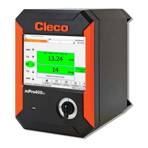
Cleco mPro300GCD-STO User manual

For additional product information visit our website at www.ClecoTools.com
Hardware Description
P2552HW
2021-04
mPro300GCD-STO
Global Controller Safe Torque Off

P2552HW |
2021-04 Apex Tool Group
Copyright © Apex Tool Group, 2021
No part of this document may be reproduced in any way or in any form, in whole or in part, or in a
natural or machine-readable language, or transmitted on electronic, mechanical, optical, or other
media, without the express permission of the Apex Tool Group.
Disclaimer
Apex Tool Group reserves the right to modify, supplement, or improve this document or the pro-
duct without prior notice.
Trademark
Cleco is a registered trademark of Apex Brands, Inc.
Apex Tool Group
670 Industrial Drive
Lexington, SC 29072
USA
Manufacturer
Apex Tool Group GmbH
Industriestraße 1
73463 Westhausen
Germany

Apex Tool Group P2552HW | 2021-04 3
INT
Content
EN
1 Notes on this Description ................................................................................ 6
2 Safety .............................................................................................................. 6
3 Product description........................................................................................ 10
4 Technical Specifications ................................................................................ 10
5 Pin Assignment.............................................................................................. 12
6 SD Card......................................................................................................... 14
7 Items Delivered ............................................................................................. 14
8 Accessories, optional .................................................................................... 15
9 STO safety function....................................................................................... 16
10 Operation and use......................................................................................... 20
DE
1 Zu dieser Beschreibung ................................................................................ 21
2 Sicherheit ...................................................................................................... 21
3 Produktbeschreibung .................................................................................... 25
4 Technische Daten.......................................................................................... 25
5 Steckerbelegung ........................................................................................... 27
6 SD Karte........................................................................................................ 29
7 Lieferumfang ................................................................................................. 29
8 Zubehör, optional........................................................................................... 30
9 Sicherheitsfunktion STO................................................................................ 31
10 Bedienung und Betrieb.................................................................................. 35
ES
1 Acerca de esta descripción ........................................................................... 36
2 Seguridad...................................................................................................... 36
3 Descripción del producto............................................................................... 40
4 Datos técnicos............................................................................................... 40

4 P2552HW | 2021-04 Apex Tool Group
INT 5 Asignación de enchufes ................................................................................ 42
6 Tarjeta SD...................................................................................................... 44
7 Volumen de suministro .................................................................................. 44
8 Accesorios, opcionales.................................................................................. 45
9 Función de seguridad STO............................................................................ 46
10 Manejo y funcionamiento............................................................................... 51
FR
1 À propos de cette description ........................................................................ 53
2 Sécurité ......................................................................................................... 53
3 Description du produit.................................................................................... 57
4 Caractéristiques techniques .......................................................................... 57
5 Disposition des connecteurs.......................................................................... 59
6 Carte SD........................................................................................................ 61
7 Étendue de la livraison .................................................................................. 61
8 Accessoires, en option .................................................................................. 62
9 Fonction de sécurité STO.............................................................................. 63
10 Commande et fonctionnement ...................................................................... 68
ZH
1␂ℝ㦻㙞承㠖ↅ
2⸘⏷㊶
3ℶ❐㙞承
4㔏㦾㟿㗽
5㙡⯃⒕揜
66'◰
7∪徶喒⦃
8棓ↅ᧨♾折
9672⸘⏷┮厌
10 㝜⇫扟嫛

Apex Tool Group P2552HW | 2021-04 5
INT
PL
1 Informacje dotyczące tego opisu................................................................... 84
2 Bezpieczeństwo ............................................................................................ 84
3 Opis produktu................................................................................................ 88
4 Dane techniczne............................................................................................ 88
5 Rozkład wyprowadzeń.................................................................................. 90
6 Karta SD........................................................................................................ 92
7 Zakres dostawy ............................................................................................. 92
8 Akcesoria, opcjonalne ................................................................................... 93
9 Funkcja bezpieczeństwa STO....................................................................... 94
10 Obsługa i eksploatacja .................................................................................. 98
PT
1 Com relação a esta descrição....................................................................... 99
2 Segurança..................................................................................................... 99
3 AtençãoDescrição do produto..................................................................... 103
4 Dados técnicos............................................................................................ 103
5 Atribuição dos conectores........................................................................... 105
6 Cartão SD.................................................................................................... 107
7 Escopo de fornecimento.............................................................................. 107
8 Acessório, opcional ..................................................................................... 108
9 Função de segurança STO ......................................................................... 109
10 Manuseio e operação.................................................................................. 113
11 System ......................................................................................................... 114
12 Connections, Cable Length.......................................................................... 115
13 Dimensions.................................................................................................. 116

6 P2552HW | 2021-04 Apex Tool Group
1
EN 1Notes on this Description
The information contained within this document is intended
for all individuals responsible for connecting and installing
the controller.
mPro300GCD-STO
Software instructions are provided in separate program-
ming manuals based upon the version installed.
The original language of this document is German.
Minimum Software Requirements
Additional Document References
Important Symbols
2 Safety
2.1 General Requirements
Only operate the controller after reading and fully
understanding this document. Failure to follow the
directions and safety instructions could result in elec-
tric shocks, burns and/or serious injuries.
Keep this document in a safe place for future refer-
ence! These safety instructions must be accessible all
personnel programming, operating or repairing the
controller.
2.2 Intended Use
The controller is a part of the Cleco Production Tools Tight-
ening System and is intended exclusively for industrial use
in fastening processes. Only use the controller under the
following conditions:
• In accordance with the components listed in the EC
Declaration of Conformity.
• Identified environmental conditions; see relevant docu-
mentation.
• Appropriate supply voltage; reference respective docu-
mentation.
• In EMC Limit Class A (electromagnetic immunity for
industrial areas). For the currently observed EMC
standards, see the EC Declaration of Conformity.
2.3 Foreseeable incorrect usage
Bridging safety devices is not permissible.
Do not use the controller:
• in potentially explosive areas
• in damp locations or outdoors
• in combination with cutting tools (drills, milling cutters,
grinders…)
• in non-industrial applications (eg residential area).
• For fastening applications not mentioned in the decla-
ration of conformity
• as climbing aid.
2.4 Operator Training
The tightening system may only be put into operation,
adjusted and tested by qualified and trained personnel.
Personnel must be instructed by qualified employees of
Apex Tool Group.
The controller has been preset by Apex Tool Group.
Adjustmenty of the controller to accommodate special
requirements may only be carried out by a qualified per-
son1).
Additional information are available in the Programming
Manual.
No. Description
S168300 Controller Software, Standard
S168677 mProRemote – Interface software between an
external computer and controller
No. Document type
P1730PM Reference Handbook
Fastening Sequences
P2279SB Systemhandbook NeoTek
P2461JH Quick Installation Guide mPro300GCD
P2486PM Programming Manual
mPro300GCD Standard Software
P3364C EC Declaration of Conformity
mPro300GCD-STO
Italic Identifies menu options), input fields, control
boxes, options fields or dropdown menus.
> Denotes the selection of a menu option from
a menu, e.g. File > Print
<…> Denotes switches, pushbuttons or keys of an
external keyboard, e.g. <F5>
Courier Denotes filenames and paths, e.g.
setup.exe
• Denotes lists, level 1
- Denotes lists, level 2
a)
b)
Denotes options
→Denotes results
1. (…)
2. (…)
Denotes action steps in sequence
Denotes a single action step
Sales &
Service
Centers
Cleco Production Tools – Sales & Service
Centers, see last page.
1 Due to their training, knowledge, experience and understand-
ing of the circumstances involved in this kind of work, suitably qual-
ified personnel are able to identify potential hazards and to initiate
appropriate safety measures. Qualified personnel are obliged to
comply with regulations.

Apex Tool Group P2552HW | 2021-04 7
1
EN
2.5 Personal Protective Equipment
(PPE)
When working with rotating parts, it is not permitted to
wear gloves.
Recommendation: Freely rotating u-GUARD pro-
tected fastening tools are available from APEX.
Wear close-fitting clothing.
Wear safety shoes.
If necessary, wear a hairnet.
Wear protective goggles, if there is a risk of flying
debris or parts being elected.
2.6 Warnings and Notes
Warning notes are identified by a signal word and picto-
gram:
• Signal word: describes the severity and the probability
of the impending danger.
• Pictogram: describes the type of danger.
2.7 Symbols on the Product
Be sure to understand the meaning of each symbol below
prior to installation, operation or maintenance service.
2.8 Standards
2.8.1 FCC and IC compliance
This product complies with Part 15 of the FCC Rules. Any
changes or modifications not expressly approved by the
manufacturer could void the user's authority to operate this
product. Operation is subject to the following two condi-
tions:
• this product may not cause harmful interference, and
• this product must accept any interference received,
including interference that may cause undesired oper-
ation.
FCC Responsible party
Name: William Cain
Position: Director, R&D
Address: 670 Industrial Drive
Lexington, SC 29072
United States
Phone: +1 803 951 7558
Email: William.Cain@ClecoTools.com
This product has been tested and found to comply with the
limits for a Class A digital device, pursuant to Part 15 of
the FCC Rules. These limits are designed to provide rea-
sonable protection against harmful interference when the
product is operated in a commercial environment. This pro-
duct generates, uses, and can radiate radio frequency
energy and, if not installed and used in accordance with the
instruction manual, may cause harmful interference to
radio communications.
Operation of this product in a residential area is likely to
cause harmful interference in which case the user will be
required to correct the interference at his own expense.
2.9 System Relevant Safety
Instructions
Follow national, state and local safety and connection stan-
dards during installation. The standards take precedence
over the information in this section.
Danger
Symbol combined with the word Danger in-
dicates a hazard with a high level of risk
which, if not avoided, will result in death or
serious injury.
Warning
Symbol combined with the word Warning
indicates a hazard with a medium level of
risk which, if not avoided, could result in
death or serious injury.
Caution
Symbol combined with the word Caution in-
dicates a hazard with a low level of risk
which, if not avoided, could result in minor or
moderate injuries or environmental dam-
age.
Note
An symbol combined with the word Note in-
dicates a potentially harmful situation which,
if not avoided, could result in damage to
property or the environment.
General notes
includes application tips and useful infor-
mation, but no hazard warnings.
Electrical voltage
CE compliant
The product corresponds to the prescribed
technical requirements in Europe.
Read all instructions.

8 P2552HW | 2021-04 Apex Tool Group
1
EN Do not make any modifications to the controller, pro-
tective devices, or accessories without prior written
authorization from Apex Tool Group.
Do not attempt to open the controller or components of
the controller for troubleshooting or other work on the
device. In the event of a fault, any intervention can
result in serious injury from electric shock.
Operation with the device open may also cause the fol-
lowing:
- An increased amount of emissions: may produce
interference with other devices.
- Reduced immunity from interference: may produce
faulty results.
- Loss of remaining warranty period.
Risk Of Injury Due To Electric Shock
The controller and tool can conduct current in the event of
a fault. An electric shock can lead to cardiac arrest, cessa-
tion of breathing, burns, and serious or fatal injuries.
Always turn off the controller before connecting power
and tool cables, cleaning or removal from operation.
Do not operate the tightening system if the housing,
cable or tool are damaged.
Installation
Use an approved hoist to raise controller to desired
installation location.
Ensure the controller is rigidly mounted and
secured(see Quick Installation Guide).
Organize cables and lines to avoid damage and trip-
ping hazards.
Observe the permitted cable bending radius.
In the event of a fault, high leakage currents may occur and
cause injuries by electric shock.
Use an approved power cable, with suitable ratings.
Prior To Initial Operation
Only operate on a grounded power supply with a neu-
tral conductor (TN system). Operation without a neu-
tral conductoron (IT system) is not permitted.
Ensure a standard-compliant PE connection is in
place.
A ground fault circuit interrupter (GFCI) type A is rec-
ommended to protect the supply line.
Prior to initial operation, carry out the protective con-
ductor measurement in accordance with the local reg-
ulations (in Germany, DGUV Regulation 3).
Do not switch on the controller until all connections
have been made correctly.
Operation
Protect the controller from moisture.
Immediately power off the controller in the event of
unusual noise, heating or vibration from the tool.
Disconnect the power cord and have the tightening
system checked by qualified personnel and repaired if
necessary.
Never pull the power cord to remove from an outlet.
Protect all cables from heat, oil, sharp edges and mov-
ing parts.
Replace damaged cables immediately.
Ensure tool and plug connections between the
controller and tool are clean.
Ensure the workstation and surrounding area are
clean.
Ensure the workstation provides adequate space for
the operation being completed.
When working with a nutrunner, remain alert at all
times. Do not use a nutrunner if you are tired or under
the influence of drugs, alcohol or medication. A
moment of carelessness when working with a nutrun-
ner may contribute to a life threatening situation.
Danger Due To Incorrect Torque Measurement
An undetected NOK tightening may contribute to a life-
threatening situation.
Recalibration (or capability analysis) is essential fol-
lowing incorrect use (crash, mechanical overload…).
For Category A Tightenings (VDI 2862) which are criti-
cal for safety, activate a redundancy measurement
(e.g., current redundancy).
Introduce regular monitoring of measuring equipment
for associated manufacturing equipment.
Only conduct tightening operations with a properly
functioning system. If in doubt, contact Sales & Service
Centers.
Danger Due To Unexpected Start Of The Motor Or An
Expected But Missing Stop
Despite redundant controller parts and monitoring func-
tions, an unexpected start of the machine can occur in very
rare cases. Possible reasons may include, but are not lim-
ited to: Remote control of diagnostic functions, bit dump in
the memory of the controller.
Mechanical hazards such as jars/jolts due to counter
torques; risk of injury due to winding up and seizing can
result from the tool.
Use the tool at the designated grip points.
Use the recommended reaction devices. For torques,
reference appropriate tool instruction manual.
After powering the controller on, wait until the boot
cycle is completed, approximately 60 seconds, before
powering it down again.
Use of Secondary controllers
Up to 15 Secondary Controllers can be added to a Primary
Controller. Upon shutting off or in case of a Secondary
Controller failure, the TSNet bus communication is inter-
rupted. The communication loss to the Primary Controller
has consequences for a Secondary Controller:
→No results are returned to the Primary Controller.
→Additional rundowns are not initiated.
→An in-process rundown is reported with the error
message SA (abort by removing the start signal) if
the TSNet connection is interrupted during tighten-
ing.
→A shut-off signal is no longer received and so a
shut-off is only possible
- via the start button of the tool
- after reaching the shut-off criterion
- via a safety shut-off after two seconds
WARNING!

Apex Tool Group P2552HW | 2021-04 9
1
EN
During remote-start operation (multiple tool setup) an inter-
ruption of TSNet bus leads to a delayed stop of the spindle/
tool. This delay is 2 seconds.
Maintenance
The controller is generally maintenance-free.
Consider local regulations for maintenance and servic-
ing for all operating phases of the tightening system.
Cleaning
Only clean the exterior of the tool using a dry or slightly
damp cloth.
Do not immerse the controller or tools in any liquids.
Do not use a high pressure or abrasive cleaner.
Disinfection of surfaces with alcohol-based disinfectant
is permitted.
Repair
Repairs to the equipment are not permitted.
Send the controller to a Authorized
Cleco Production Tools Sales & Service Centers.
Disposal
Components of the tightening system may present poten-
tial risks the environment. The tightening system contains
components that can be recycled, as well as components
that have specific disposal requirements.
Follow local applicable regulations.
First separate, then dispose of components.
Collect auxiliary materials (oils, greases) and dispose
properly.
Separate the components of the packaging and dis-
pose of them according to local regulations.
Return defective equipment to an approved collection
point or return it to the Sales & Service Centers.
Observe local regulations for disposal of
electronics and batteries. (In Germany,
the Electrical and Electronic Equipment
Act (ElektroG) and the Battery Act
(BattG)):
Used up batteries must be disposed
of properly. Return depleted or defec-
tive batteries to an approved collec-
tion facility or to Sales & Service
Centers for recycling.

10 P2552HW | 2021-04 Apex Tool Group
1
EN 3 Product description
Controller for use in safety-critical tightening.
The controller is primarily used as a control and monitoring
unit for one or more tools at a workstation. Depending on
the peripheral devices that are procured, the controller can
also be installed outside of the work environment.
Software is already installed on the controller. The tighten-
ing settings must be carried out by a qualified person using
the controller or remote PC software (mProRemote) in
order to start fastening work. For further information
regarding software operation, please reference the Pro-
gramming Manual.
Nutrunner controllers with the suffix STO in the type name
are equipped with the STO safety function, see Chapter 9
STO safety function, Page 16.
4 Technical Specifications
Ambient Conditions
Power Supply
Safety Technology
Normative references
For product-relevant EC Directives, as well as the stan-
dards complied with, see the EC Declaration of Conformity.
Features Data
Operation Site Indoors
Ambient Temperature 0...45 °C1
1 Note the derating. See System Handbook NeoTek™
Storage Temperature -20...70 °C
Type of Cooling Convection (self-cooling)
Relative Humidity 10...90 %
No Condensation
Working Height Up to 3000 m
Above Sea Level1
Protection Class
DIN EN 60529
IP42
Protection Class
DIN EN61140
(VDE 0140-1)
I
Degree of Contamination
EN 61010
2
Transient Overvoltage
EN 61010
CAT
Maximum Shock
DIN EN 60068-2-27
15 G
Maximum Vibration
DIN EN 60068-2-5
59.6–160 Hz: 2 G
Features Data
Supply Voltage,
Single Phase
100–240 VAC ± 10%1
1 When operating outside the allowable voltage limits,
the integrated power supply enters a protection mode
and switches off. This protection mode can be reset
by restarting the nutrunner controller.
Rated Supply Current 2–1 A
Frequency 50/60 Hz
Peak Current 16 A
Rated Power 1600 VA max.
Idling 40 VA
Safety indices
Safety
function
STO Safe start lockout (STO, Safe
Torque Off) in accordance with
EN 61800-5-2, with SIL 2
Safe start lockout (STO, Safe
Torque Off) in accordance with
EN ISO 13849-1, Category 3 and
PL d
SIL SIL 2 Safety level (Safety Integrity
Level) in accordance with EN
61800-5-2
Category 3 Classification in the category is in
accordance with EN ISO 13849-1
PL PL d Performance Level is in accor-
dance with EN ISO 13849-1
DCavg 60% Low, average diagnostic cover-
age (Average Diagnostic Cover-
age)
HFT 1 Hardware Failure Tolerance
SFF > 60% Safe Failure Fraction
PFH 9.1 E-10 1/h < 0.1% of SIL 2, Probability of
dangerous Failure per Hour
PFDav
(T = 20 a)
7.9 E-05 0.8% of SIL 2, Probability of dan-
gerous Failure on Demand
TPTI
[months]
12 Proof Test Interval service life in
accordance with EN ISO 13849-1
MTTFd > 2.000 a HIGH, Mean time to dangerous
failure

Apex Tool Group P2552HW | 2021-04 11
1
EN
NRTL Certification
Electrical specifications
System Data
Weight
Issuing agency TÜV SÜD
North America
Certificate No. U8V 078313 0010 Rev. 00
Tested in accordance with • UL 61010-1:2012/
R:2018-11
• CAN/CSA–C22.2
No.61010-1:2012/
A1:2018-11
International
Certificate No. DE 3 - 31485
Tested in accordance with • IEC 61010-1:2010
• IEC 61010-1:2010/
AMD1:2016
Control signals STO-A and STO-B at [X41] and [X42]
Nominal voltage [VDC] 24 (based on GND_STO)
Voltage range [VDC] 0 … 28.8
Allowed residual ripple [%] 2 (based on nominal voltage;
leaving the voltage range is
not allowed)
Input current [mA] 4 (typical for 24 V)
Switching threshold On
[VDC]
> 17
Switching threshold Off
[VDC]
< 4.5
Switching time On [ms] < 1
Switching time Off [ms] < 1
Feedback contact FB1, FB2 [X41]
Max. voltage [VDC] < 30
Nominal current [A] 0.5
Resistance [Ω] < 1 (switched on)
Residual current [μA] < 2 (switched off)
Auxiliary supply 24 V [X41]
Nominal voltage [VDC] 24
Nominal current [mA] 100 (short circuit proof)
Features Data
System Functions Battery Buffered Real Time Clock,
Buffer Time: 10 Years (at 20 °C)
Display LC Display With Touchscreen,
7" TFT Liquid Crystal Display,
Resolution 480 x 800, Connection To
Panel & Touch Possible
Operating System Linux, Bootable Without Mechanically
Moving Drives, No UPS Required
HMI
(Human Machine
Interface)
Virtual Keyboard for Alphanumeric
Inputs
Model Weight
Ib kg
MPRO300GCD-STOEMEA
MPRO300GCD-STONA
MPRO300GCD-STOAPAC
11,9 26,2
including mounting plate 13 28,7
Features Data

12 P2552HW | 2021-04 Apex Tool Group
1
EN 5 Pin Assignment
This chapter describes the Cleco Production Tools specific
connectors. Standard plugs are not considered. All connec-
tions are short-circuit proof.
X5 – Serial port for additional devices
• All outputs provide RS232 conforming signals.
• The inputs allow voltages in the range from -15 V to
+15 V.
- Voltages < 0.8 V correspond to a zero.
- Voltages > 2.4 V are interpreted as a one.
- Open inputs are preset to zero using a pulldown
resistor.
• The power supply pins are connected directly to the
main board power supply
.
X7 – Anybus Compact Com
X21 – TSnet System Bus Out
Interface port for TSnet cable.
X22 – TSnet System Bus In
X23 – Supply
X24 – Tool Connector Digital
for 30/50/70/BD Series
Note
Do not connect or disconnect any device
during operation. Doing so may result in a
system reset.
Pin RS232-1 9 Pin D-Sub Male
with Screw Lock
1 –
2 RxD
3 TxD
4 –
5 GND
6 –
7 RTS
8 CTS
9 –
Module Order no.
PROFINET M40 RJ45 544357PT
PROFIBUS M40 M12 962291PT
PROFIBUS M40 DB9 962292PT
DeviceNet M40 962293PT
PROFINET M40 M12 962294PT
Ethernet/IP M40 RJ45 2 port 962297PT
Modbus/TCP M40 RJ45 2 port 962299PT
Note
Do not combine Anybus Compact Com M40
modules with Anybus CC M30 modules.
Pin Signal 8 Pin M12 Socket
Circular Connector X-Coded
1 Tx +
2 Tx -
3 Rx +
4 RX -
5 0 VDC
6 0 VDC
7 +24 VDC
8 +24 VDC
Pin Signal 8 Pin M12 Male
Circular Connector X-Coded
1 Tx +
2 Tx -
3 Rx +
4 RX -
5 0 VDC
6 0 VDC
7 +24 VDC
8 +24 VDC
Description IEC Conncetor
C14
Connector with Fuse Holder
2-Pin, 5 × 20 mm,
16 A Slow-Blow
Fuse, Schurter type 0034.3129,
5 × 20 mm, 16 AT, 250 VAC,
Interrupting Current, 100 A
Note
Use plug locking mechanism.
See Quick Installation Guide.
Pin Signal M23 Circular Connector
1-3 Power
4 PE
(functional
ground)
5 Tool bus
54
3
2
18
7
6
45
6
7
81
2
3
1
2
3
4
5

Apex Tool Group P2552HW | 2021-04 13
1
EN
X41, X42 – E-Stop
Signal assignment see 9.2.2 Interface overview, Page 17.
X9, X10 – Input/Output
Digital I/O Interface
The required signal circuits are connected to these input/
output connectors. The signal groups are connected to the
power supply.
• 8 inputs/8 outputs, optically isolated for 24 V level
• Output current: 500 mA per output, 1000 mA total
Connectors – Internal power supply
Example:
Inputs
• Internal 24 V power supply for the controller.
• Pin 11 and 23 (common GND) serve as a "return line"
for the outputs.
• Pin 11 and 23 must be connected to Pin 12 or 24 with
jumpers.
Outputs
• Internal 24 V power supply for the controller
• Pin 2 and 14 (common output) are the voltage source
for the inputs.
• Pin 2 and 14 must be connected to Pin 1 or 13
STO Function 8 Pin M12 Circular
Connector
X42 OUT Pin
X41 IN
Socket
Note
A single device must not require a current of
more than 500 mA. The current monitor
switches off the output in the event of an
overcurrent.
Phoenix Mini Combicon MCD 1,5/12-G1F-3,81
X9 X10
Signal X9 Signal X10
Pin I/O Name Pin I/O Name
12 Supply GND Int. 24 Supply GND Int.
11 Supply GND I/O 23 Supply GND I/O
10 Output O3 22 Output O7
9 Output O2 21 Output O6
8 Output O1 20 Output O5
7 Output O0 19 Output O4
6 Input I3 18 Input I7
5 Input I2 17 Input I6
4 Input I1 16 Input I5
3 Input I0 15 Input I4
2 Supply +24 V O 14 Supply +24 V O
1 Supply +24 V Int. 13 Supply +24 V Int.

14 P2552HW | 2021-04 Apex Tool Group
1
EN Connectors – external power supply
Example:
Inputs
• The external 24 V power supply for the controller must
be SELV (Safety Extra Low Voltage) or PELV (Protec-
tive Extra Low Voltage).
• Pin 11 and 23 (common GND) serve as a "return line"
for the outputs.
• The GND for the external 24 V power supply must be
used as the return line for Pin 11 and 23.
Outputs
• The external 24 V power supply for the controller must
be SELV (Safety Extra Low Voltage) or PELV (Protec-
tive Extra Low Voltage).
• Pin 2 and 14 (common output) are the voltage source
for the inputs.
• Pin 2 and 14 must be connected to the external 24 V
power supply.
6 SD Card
Required for the operation of the controller, the archiving of
data and configurations. Not included with the controller. 7 Items Delivered
Check delivery for transit damage and ensure that all items
have been supplied:
• Controller
• EC Declaration of Conformity
• This Hardware Description
• Quick Installation Guide
• Warranty
• Order no. SWB-S168300 – SD card plus Software
• Order no. S981211 – Mating Connector X9/X10 (2×)
• Order no. 962405PT – STO plug, bridged
Power Cord V Lock, varies by model:
Signal X9 Signal X10
Pin I/O Name Pin I/O Name
12 Supply GND Int. 24 Supply GND Int.
11 Supply GND I/O 23 Supply GND I/O
10 Output O3 22 Output O3
9 Output O2 21 Output O2
8 Output O1 20 Output O1
7 Output O0 (linking OK), e.g. 19 Output O0 (linking OK), e.g.
6 Input I3 (tool start), e.g. 18 Input I3 (tool start), e.g.
5 Input I2 17 Input I2
4 Input I1 16 Input I1
3 Input I0 15 Input I0
2 Supply +24 V O 14 Supply +24 V O
1 Supply +24 V Int. 13 Supply +24 V Int.
+-
Note
Only remove or plug in the SD card when
the supply voltage is switched off. Other-
wise, serious system errors and data loss
will result.
• Order no. 962276PT mPro300GCD-STO-EMEA
• Order no. 962278PT mPro300GCD-STONA 115 VAC
•–
(see Accessories)
mPro300GCD-STOAPC

Apex Tool Group P2552HW | 2021-04 15
1
EN
8 Accessories, optional
• Order no. 962037-(…) – Cable TSNet
• Order no. 961924-(…) – Cable STO
• Order no. 962199PT – Housing for connector X9/X10
• Order no. 961893PT – Termination plug
Power Cord V Lock:
Power Cord
• Order no. 962277PT 230 VAC UK
• Order no. 962311PT 230 VAC APAC
• Order no. 541863-02 230 VAC NA

16 P2552HW | 2021-04 Apex Tool Group
1
EN 9 STO safety function
9.1 Definition
The STO safety function enables the controller mPro300GCD-STO to provide a reliable solution for switching off the
energy supply at the output of the built-in nutrunner.
If several mPro300GCD-STO units are wired in series with STO connector cables, the STO function is guaranteed for the
complete group.
STO = Safe Torque Off. For the currently observed standards, please refer to 4Technical Specifications.
9.2 Performance features
• Reaching the STO safety function
• Potential-free feedback contact for the operating status.
Warning
Risk of electric shock
The STO safety function only provides protection against dangerous movements, not against electric
shock.
Always comply with the stipulations of the documentation, in particular 2 Safety, Page 6.
Comply with the documentation for the other components.
Ensure protection against the built-in nutrunner automatically restarting according to the required safe-
ty category of emergency stop applications, e.g. via an external safety relay.
STMD-H
672 $
672 %
9'&
9'&
,&
,&
,&
,&
w&
5(/
5(/
50 672$ 21
50 672% 21
24V 0V
1Pin 2 4 5 6 8 7 3 4Pin 5 6 8 7 3
Connection to the previous controller
or to a safety relay STO cable to the next
controller
Termination connector
STO connection flange
X41 IN
Connection
XS4
Auxiliary power
supply
24 V
Galvanic
separation
Power supply
Gate driver
OS + US
Activation of the
level converter for
gate signals
STO connection flange
X42 OUT
or

Apex Tool Group P2552HW | 2021-04 17
1
EN
When the STO safety function is active, the power supply
is safely interrupted by two separate shutdown paths to the
motor in the tool. The motor can not produce any torque
and therefore no dangerous movements. There is no moni-
toring of the standstill position. This is relevant, for exam-
ple, for torques generated by loads, such as suspended
loads, or by preloaded spring drives. In such cases, addi-
tional measures for shutdown must be provided that pre-
vent these reactions - these must be ensured and brought
about in a safety-related manner.
9.2.1 Diagnostic Coverage (DC)
The Diagnostic Coverage depends on the inclusion of the
integrated safety function for the controller into the
controller chain, as well as the implemented measures for
the diagnostics.
If a fault is detected during the diagnostics, suitable mea-
sures must be provided to maintain the safety level.
9.2.2 Interface overview
The STO safety function for the controller is controlled via
the digital I/O interfaces X41, X42. The interfaces for all
controllers with the STO function are designated the same,
color-coded and functionally identical with the same speci-
fications, see 5 Pin Assignment, Page 12.
The STO safety function is requested exclusively via the
two digital control inputs STO-A and STO-B. Another con-
nection of the signals, e.g,. feedback or auxiliary voltage, is
not absolutely required.
The state of the STO safety function is reported back via a
potential-free feedback contact (closer). This information is
linked in a successive circuit of several controllers with the
STO function.
Interface port X41 – IN
Depending on the position of the currently considered con-
trol in the STO line (see 11 System, Page 114), the inter-
face port X41 is the connection to the previous controller or
to the external safety relay.
By providing an auxiliary power supply of 24 VDC in con-
nector X41, it is possible to supply the voltage to safety
relays for normally open contacts, or similar.
Interface port X42 – OUT
Depending on whether the currently considered controller
is the last in an STO line, or whether another controller fol-
lows, the interface X42 is the connection to the next
controller or can be left without connecting further. If the
feedback contact is evaluated, a termination on the last
controller in a line is necessary.
Caution
There is a risk of the motor starting up when
there multiple errors in the controller.
If the final stage of the nutrunner module
in the controller fails during the STO state
(simultaneous short circuit of 2 power
semiconductors in different phases),
there may be a limited locking movement
of the rotor in the motor. The angle of ro-
tation corresponds to a pole pitch, which
acts on the output drive with the gear re-
duction. The angle of rotation for electric
hand tools from Cleco Production Tools is
always ≤15°.
Note
Cross-connection detection of the input cir-
cuit is not performed by the controller.
All system components allow the short cir-
cuit fault exclusion.
Pin Signal Description
1 24 VDC Output auxiliary power supply 24
VDC, for passive control of STO
Reference potential is GND_STO
2 24 VDC
3 FB-1-In Potential-free Feedback Contact 1
(informative) for the STO state
• Feedback contact open: STO not
active
• Feedback contact closed: STO
active
4 STO-A Input for control signal A for con-
trolling the STO safety function
Reference potential is GND_STO
• STO request at low level simulta-
neously with low level at STO-B
5 GND_STO Reference potential for all voltages at
X41
6STO-B Input for control signal B for con-
trolling the STO safety function
Reference potential is GND_STO
• STO request at low level simulta-
neously with low level at STO-A
7FB -2 Potential-free Feedback Contact 2;
for a description, see FB-1
8GND_STO Reference potential for all voltages at
X41

18 P2552HW | 2021-04 Apex Tool Group
1
EN
9.3 Control signals STO-A and STO-B
With the two control inputs STO-A and STO-B, the STO
safety function is requested by two channels. They allow
the direct connection of safe semiconductor outputs (elec-
tronic safety relays, active safety sensors) and of switching
contacts (safety relays with relay outputs, passive safety
sensors, such as positively driven position switches),
see9.6 Assembly and installation, Page 19.
To request the STO safety function, the 24 V control volt-
age at both control inputs STO-A and STO-B is switched
off (0 V). If both control signals are switched off simultane-
ously or within a specified discrepancy time, then the STO
safety function is active.
Tolerance ranges are defined for the input voltage range of
the control inputs STO-A and STO-B. The amount of
energy stored in the components of the STO circuit (e.g.,
capacitors) depends on the magnitude of the input voltage.
During switching operations, these amounts of energy
must be charged or discharged. As a result, the dependent
values for the switch-off time for the transition to the safe
state (STO) come about from the input voltage.
The requirements for the time response result from the
technical specifications in Chapter 4 Technical Specifica-
tions, Page 10.The time response itself is described in
Chapter9.5 Time response, Page 19.
Discrepancy time
The transition between a safe and an unsafe state is initi-
ated by level changes at the control inputs STO-A and
STO-B. According to the specifications for the safety func-
tion, both levels must be identical; otherwise an error mes-
sage will be generated. A state machine in the controller
monitors both signals over time. Due to component toler-
ances or bouncing contacts, the level changes never occur
at exactly the same time. This is tolerated by the so-called
discrepancy time as long as the level changes occur within
this time. If the levels of the control signals STO-A and
STO-B are different for longer than this time, a transition is
made to an error state that can not be reset. The discrep-
ancy time Δt is 100 ms. This can not be parameterized.
Test pulses
Test pulses from safety controllers are not tolerated and
must be deactivated for system availability. The exclusive
use of Cleco Production Tools accessories allows the short
circuit fault exclusion.
Feedback contact FB
The feedback contact indicates the safe state. If the STO
safety function is not active, then the feedback contact is
open. This is also the case, for example, when the 24 V
logic supply voltage is switched off due to a defect or a fail-
ure of the supply voltage. When the STO safety function is
active, the relay contact is closed.
The following table shows the state of the feedback con-
tact, depending on the input signals and the time. A pre-
condition is always the error-free state (Row 1 or 4). The
time Δt is the discrepancy time 100 ms.
The technical specifications for the feedback contact are
given in Chapter 4 Technical Specifications, Page 10.
Pin Signal Description
1NC
2
3FB-1-Out Potential-free Feedback Contact 1
4STO-A Output for control signal A for con-
trolling the STO safety function of the
next controller, bridged with X41.4
5GND_STO Reference potential for all voltages at
X42
6STO-B Output for control signal B for con-
trolling the STO safety function of the
next controller, bridged with X41.6
7FB -2 Potential-free Feedback Contact 2,
bridged with X41.7
8GND_STO Reference potential for all voltages at
X42
Chapter 4 Technical Specifications,
Page 10 describes the technical specifica-
tions for the controller inputs in the speci-
fied operating range of logic voltages.
The signals STO-A and STO-B should be
switched simultaneously if possible.
Note
The feedback contact has a single-chan-
nel design and may be used for diagnos-
tic purposes, but not in the safety circuit.
When switching on, the feedback contact
may briefly deviate from the input signals
until the nutrunner control is ready for op-
eration.
Row STO-A STO-B FB
closed
Leads to
diagnostic
error
after Δt
10 0 1 0
20 1 0 0→Δt →1
31 0
0 →Δt →1 0 →Δt →1
41 1 0 0

Apex Tool Group P2552HW | 2021-04 19
1
EN
9.4 Diagnostics
The STO safety function is monitored in the controller for
plausibility and operability.
9.4.1 STO status signal to control
Within the software, the status of the STO safety function
(1=OK, 0=STO triggered) is available at Input 15 on the I/O
level under device PM_DIDO.
If this status information is present in the application, this
must be assigned accordingly by the operator.
It is advisable to use the software input Emergency Stop.
Assignment is not necessary for safety reasons.
9.4.2 Fail-Safe state
If a fault in the safety technology is detected, e.g., if, for
example, control signals STO-A and STO-B have unequal
levels or there is a circuit defect, then a fault is triggered
internally. This fault can not be reset or can only be reset
by a restart, i.e., further start attempts no longer lead to the
turning on of the output drive.
It is assumed that there is an external fault and the
controller must be switched off. If the fault persists after
checking the external controller, then there is a defect in
the controller and it must therefore be replaced.
9.5 Time response
The control signals STO-A and STO-B are equivalent in
regards to their use, although the signals operate different
shutdown paths. They are described in terms of the time
response as a single, exchangeable STO signal.
The time from the shutdown of an STO signal to the activity
in the final stage of the controller is determined by the
external circuitry (see also9.3 Control signals STO-A and
STO-B, Page 18), including controllers connected in paral-
lel. The values given here refer to the Passive version (see
9.6.1 Passive circuit X41, Page 19) with a nutrunner con-
trol and the maximum cable length. The time response is
different for each layout and must be checked at startup to
see if it meets the minimum requirements.
9.6 Assembly and installation
When installing and wiring the signals, the requirements of
EN 60204-1 must be met. In this case, particular attention
must be paid to measures for short circuit fault exclusion.
For the STO cables 961924-xxx, the STO signals are indi-
vidually protected by a ground connection. The connection
to the first controller, and from controller to controller, must
not be longer than 60 m; in total in the system, a total
length of up to 1000 m is permitted for all of the STO con-
nections.
The following circuit examples show the intended wiring of
the STO interfaces. An analogous other use or connection
is not permitted.
9.6.1 Passive circuit X41
Fig. 9-1:
The STO safety function can be requested by various devices. The switch S1 can be, for example, an Emergency Stop
switch, a safety door switch, a light curtain or a safety relay. The safety requirement is 2-channel via the switch S1and
leads to the 2-channel shutdown of the final stage - therefore, this structure is for Category 3. The auxiliary power supply
24 V for signal generation is provided on the interface.
9.6.2 Active circuit X41
Fig. 9-2:

20 P2552HW | 2021-04 Apex Tool Group
1
EN The STO safety function can also be requested through active, fail-safe outputs of a PLC or with contacts as in Chap-
ter9.6.1 Passive circuit X41, Page 19, but with an external power supply. For an external power supply, only PELV power
circuits and PELV power sources may be used. The voltage source must provide a nominal voltage of 24 VDC (an abso-
lute minimum output voltage of 22 VDC) with at least 0.5 A.
9.6.3 Shut down of STO safety function X41
Fig. 9-3:
If the STO safety function is not required in a controller, the function can also be deactivated by means of jumpers in a
connector as shown in the circuit diagram Fig. 9-3:.
9.6.4 Connection X42
Fig. 9-4:
The connection to X42 at the last controller in a system is only required if the feedback contact FB is evaluated. Otherwise,
the X42 interface can also remain open. For termination - which means closing the feedback path - use termination con-
nector 961893PT.
10 Operation and use
10.1 Obligation of the operator
Check the functioning of the safety device at defined time
intervals. It is the responsibility of the operator to choose
the type of test and the time intervals during the required
time period. The test shall be carried out in such a way that
the proper functioning of the safety device is demonstrated
in the interaction with all the associated components. The
maximum interval between two tests may not exceed a
duration of TPTI, see 4 Technical Specifications, Page 10.
10.2 Overvoltage and polarity reversal
protection
The control inputs STO-A and STO-B are protected against
overvoltages and against the polarity reversal of the control
voltage, see also Chapter4 Technical Specifications,
Page 10.
The 24 VDC auxiliary voltage supplied at X41 is short-cir-
cuit proof. However, a short circuit or overload leads to the
failure of alll the internal logic voltages and thus to the fail-
ure of the primary function.
Caution
Never temporarily use the connections shown here for another system whose risk assessment re-
quires an STO safety function.
The risk of forgetting is given.
Table of contents
Languages:
Other Cleco Controllers manuals
Cleco
Cleco mPro400GCD-P Guide
Cleco
Cleco TME-100 Owner's manual
Cleco
Cleco DGD mPro400GC User manual
Cleco
Cleco mPro400GCD-M User manual
Cleco
Cleco DGD mPro400GC Guide
Cleco
Cleco CellCore 200 Series Guide

Cleco
Cleco mPro400GCD-P Guide
Cleco
Cleco DGD mPro400GC User manual
Cleco
Cleco mPro400GCD-S User manual

Cleco
Cleco DGD mPro400GC Owner's manual
Popular Controllers manuals by other brands
UCS
UCS T-RACK user manual
Sanhua
Sanhua SEC60 Series Manual and installation instructions
Fuji Electric
Fuji Electric MICREX-F Series manual
ZIEHL-ABEGG
ZIEHL-ABEGG Acontrol PSET6 operating instructions

dynarex
dynarex Oxygen Regulator CGA 870 Style user manual
Neptronic
Neptronic LT060X11 Specification & installation instructions
