Cleco TME-100 Owner's manual

Electric Tool Control
TME Series
Version 2.5.2
Reference Document: PL12-1404 Parts manual
For additional product information visit our website at http://www.cooperpowertools.com
Programming Manual
PL12EN-1300
2008-03

2 PL12EN-1300 2008-03 en00d141.fm, 11.03.2008
Disclaimer:
The information and data in this document has been prepared to the best of our ability.
Nonetheless, differences between the information and the actual product cannot be
excluded with absolute certainty. Cooper Power Tools does not assume any liability for
consequential errors and damages. We likewise do not assume liability for damages
resulting from defective circuitry inside the devices supplied. Cooper Power Tools
reserves the right, to ammend, supplement or improve this document or the product with-
out serving prior notice.
Without the express approval of Cooper Power Tools this document must not be repro-
duced in its entirity or in part by any means; it must not be converted to any type of natu-
ral or machine readable language or be saved on data storage media of electronic,
mechanic, optical or other type.

PL12EN-1300 TME-200 V2.5.2 0108IVZ.fm, 11.03.2008 PL12EN-1300 2008-03 3
Contents
1 Getting Started 7
1.1 Safe Work Practices Symbol ................................................................ 7
1.2 Checking Your Unit ............................................................................... 7
1.3 Software................................................................................................ 7
1.4 Installing Unit ........................................................................................ 7
1.4.1 General ................................................................................................. 7
1.4.2 Mounting ............................................................................................... 8
1.4.3 Location Considerations ....................................................................... 8
1.4.4 Source Power ....................................................................................... 8
1.4.5 Intended Use ........................................................................................ 8
1.4.6 EMC Measures ..................................................................................... 9
1.5 Connecting Unit .................................................................................... 9
1.5.1 General ................................................................................................. 9
1.6 Energizing Unit ................................................................................... 10
2 Controller Specifications 13
2.1 Understanding the Keypad ................................................................. 13
2.2 Specifications...................................................................................... 14
2.2.1 Enclosure............................................................................................ 14
2.2.2 Display ................................................................................................ 14
2.2.3 Keypad Overlay .................................................................................. 15
2.2.4 Indicators ............................................................................................ 15
2.2.5 CPU with PC 104................................................................................ 15
2.2.6 AC Input Power................................................................................... 16
2.2.7 Inernal DC Power ............................................................................... 16
2.2.8 Input / Output Connectors................................................................... 16
3 Programming 21
3.1 Navigator Menu .................................................................................. 21
3.1.1 Basic Navigation Instructions.............................................................. 21
3.1.2 Work Cell ............................................................................................ 21
3.1.3 Password Function ............................................................................. 22
3.1.4 Print Screen ........................................................................................ 22
3.1.5 Two Channel Features: General Description
(2-Channel V2.xx.xx C2 only) ............................................................. 22
3.1.6 Navigator Menu .................................................................................. 23
3.1.7 Administration ..................................................................................... 24
3.2 Basic Application Builder .................................................................... 24
3.2.1 Basic Parameters for Torque Control / Angle Monitor ........................ 26
3.2.2 Basic Parameters for Angle Control / Torque Monitor ........................ 26
3.2.3 Basic Application Builder Parameters................................................. 26
3.2.4 Advanced Parameter Default Values.................................................. 27

4 PL12EN-1300 2008-03 PL12EN-1300 TME-200 V2.5.2 0108IVZ.fm, 11.03.2008
3.2.5 Backoff using Reverse Switch (Sequence 41 or Sequence 46) ......... 27
3.2.6 Basic Application Builder / Auto Program ........................................... 27
3.2.7 Basic Application Builder / Copy......................................................... 28
3.3 Standard Application Builder............................................................... 29
3.3.1 Standard Application Builder / View Stages........................................ 29
3.3.2 Standard Application Builder / View Stages / Copy ............................ 30
3.3.3 Standard Application Builder / Select Sequence ................................ 31
3.3.4 Standard Application Builder / Parameters ......................................... 33
3.3.5 Standard Application Builder / Advanced Parameters ........................ 38
3.4 Advanced............................................................................................ 40
3.4.1 Advanced Application Builder / Application Matrix.............................. 40
3.4.2 Advanced Application Builder / Inputs ................................................ 41
3.4.3 Advanced Application Builder / Outputs ............................................. 43
3.4.4 Advanced Application Builder / Fieldbus ............................................ 46
3.4.5 Advanced / Linking ............................................................................. 51
3.4.6 Advanced Application Builder / Signals .............................................. 52
3.4.7 Advanced Application Builder / System Settings ................................ 53
3.5 RUN Screen........................................................................................ 55
3.5.1 Run Screen / Tool 2 ............................................................................ 57
3.5.2 Run Screen / Split Screen................................................................... 57
3.5.3 Run Screen / TMEI ............................................................................. 58
3.5.4 Run Screen / Configure ...................................................................... 59
3.6 Oscilloscope ....................................................................................... 60
3.7 Communication................................................................................... 61
3.7.1 Communications / Data Transmission ................................................ 61
3.7.2 Communication / Part ID..................................................................... 64
3.7.3 Communications / Printer ................................................................... 67
3.7.4 Communications / Work Cell .............................................................. 68
3.8 Tool Setup........................................................................................... 68
3.9 Tool Library ......................................................................................... 70
3.9.1 Tool Library ......................................................................................... 70
3.10 Statistics.............................................................................................. 71
3.10.1 Statistics / Chronological History ........................................................ 71
3.10.2 Statistics / Graphs............................................................................... 73
3.10.3 Statistic / Parameter............................................................................ 75
3.11 Diagnostics ......................................................................................... 76
3.11.1 Inputs / Outputs .................................................................................. 76
3.11.2 Diagnostic / Fieldbus .......................................................................... 77
3.11.3 Tool / Calibration ................................................................................. 78
3.11.4 Tool / Angle Encoder........................................................................... 79
3.11.5 Tool / Voltages .................................................................................... 80
3.11.6 Tool / TQ Measurement ...................................................................... 81
3.11.7 Tool / Speed ........................................................................................ 82
3.11.8 Tool / Tool Memory.............................................................................. 83
3.11.9 Arcnet / Map ....................................................................................... 83
3.11.10 Arcnet / Statistic .................................................................................. 84

PL12EN-1300 TME-200 V2.5.2 0108IVZ.fm, 11.03.2008 PL12EN-1300 2008-03 5
3.11.11 Serial................................................................................................... 85
3.11.12 Event Log............................................................................................ 86
3.12 Utilities ................................................................................................ 87
3.12.1 Utilities / Installed Versions ................................................................. 87
3.12.2 Utilities / Software Update .................................................................. 88
3.12.3 Utilities / System Settings ................................................................... 90
3.13 Administration ..................................................................................... 91
3.13.1 Administration / Load/Save................................................................. 91
3.13.2 Administration / Print........................................................................... 92
3.13.3 Administration / Password .................................................................. 93
3.13.4 Administration / Date & Time .............................................................. 94
3.13.5 Administration / Language .................................................................. 95
3.13.6 Administration / Counter ..................................................................... 96
4 Statistics 97
4.1 Understanding Statistics ..................................................................... 97
4.1.1 The Nature of Variation....................................................................... 97
4.1.2 The Normal Curve .............................................................................. 98
4.1.3 The Procedure .................................................................................... 98
4.1.4 System Improvement........................................................................ 102
4.2 Statistic Symbols............................................................................... 102
5 Glossary 105

6 PL12EN-1300 2008-03 PL12EN-1300 TME-200 V2.5.2 0108IVZ.fm, 11.03.2008

en01d141.fm, 11.03.2008 PL12EN-1300 2008-03 7
Getting Started 1
1 Getting Started
1.1 Safe Work Practices Symbol
!
The signal word "Warning" identifies all notes on safe work practices in this operating
instruction, alerting to hazards for life and health of people. Observe these notes and pro-
ceed with special care in the cases described. Pass all safety instructions on to other
operators. In addition to the safety instructions in this operating instruction, the general
local safety and accident prevention rules must be observed.
CAUTION! The signal word "Caution!" identifies all portions of this operating instruction meriting
special attention to ensure that guidelines, rules, hints and the correct work procedures
are observed; and, to prevent damage to and destruction of the machine and/or parts.
1.2 Checking Your Unit
Take the time to ensure you have the required peripheral equipment and cables necessary to
setup and run your unit. If you do not have all the necessary items, contact your distributor.
Refer to "Attachment A.1" on page12 for illustration of your unit.
1.3 Software
Your unit has been pre-loaded with software and requires no additional software to begin your
fastening process. If you are interfacing your unit with an external computer, interfacing software
is required. Contact your distributor for the interfacing software.
1.4 Installing Unit
1.4.1 General
!
It is mandatory that national, state and local safety and wiring standards be followed dur-
ing installation. These standards would take precedence over any information presented
in this section.
To avoid the hazard of electrical shock or burn, the following instructions must be
adhered to. Failure to follow these instructions may also cause damage to your unit and
void existing warranties.
• Do not energize the unit until all connections have been properly made.
• Equipment must be properly grounded before applying power. Units energized by cord
and plug must be connected to an approved and properly grounded receptacle.
• All units must be energized by an isolated line.
• The unit door must always be closed and secured prior to energizing the unit.
• Ensure the power switch is in the "off" position prior to connecting the power cord.
CAUTION! Though it is not mandatory, the following instructions are highly recommended for the
protected operation of your unit.
• Use an isolation transformer and surge arrestor on the incoming isolated line.
• Use oversized feeder lines to reduce electrical noise and voltage drop.

8 PL12EN-1300 2008-03 en01d141.fm, 11.03.2008
Getting Started
1
1.4.2 Mounting
Each unit is used primarily as a single tool process/controller/monitor installed in a work station
or work area. It may be wall mounted, table mounted, beam mounted, suspended overhead,
pedestal mounted or used without mounting. Always choose a stable location to avoid the possi-
bility of unit damage and/or operator injury through hitting, falling, vibration or inconvenient
mounting. All cables attached to the unit should be located and secured in a manner to avoid
potential operator and passer-by injury. As with all electrical equipment, the unit will produce
some heat and should be located so that ambient air can freely circulate around the box.
Refer to Illustration Q of the parts manual, PL12-1400 for mounting hole dimensions.
1.4.3 Location Considerations
Your unit should be located to allow access to the front panel and connectors. The unit should be
installed for unrestricted and comfortable viewing of the LCD & LED's by the operator. The LCD
menu screen, key pad and side door connectors must be readily accessible for the setup.
Dependent on the peripheral equipment purchased, the unit may be located in a remote position
but should still be accessible.
Attachment of accessories and tools should also be considered with the installation locations.
Items to be considered are:
• Location of printer (10 ft. cable maximum for the parallel interface).
• Attachment of a data collection unit, if desired.
• Attachment of redundant master transducers (less than 50 ft. is desirable).
• Attachment of remote annunciators, socket nest, or remote parameter select.
• Attachment of the unit in a network to a computer.
• Operation convenience/safety - keep cables off the floor or dangling in operator areas.
1.4.4 Source Power
Your unit, which is used as the process control and power supply for the Cleco DC electric tools,
requires a power line with 10 amp capacity at 220-240 Volts AC (50/60 Hz) for the TME-XXX-30.
The TME-XXX-15 requires a power line with 15 amp capacity at 110-130 Volts AC (50/60 Hz).
1.4.5 Intended Use
The Electric Tool Control TME Series must be operated only if the following conditions are
met:
• Industrial environment, EMC (electromagnetic compatibility) class A
• Use only the cable types approved by Cooper Power To ols.
• Use only accessory parts approved by Cooper Power Tools.
• Unauthorized remodeling, repairs, and modifications are forbidden for safety and product lia-
bility reasons.

en01d141.fm, 11.03.2008 PL12EN-1300 2008-03 9
Getting Started 1
1.4.6 EMC Measures
• The filters required to meet the EMC regulations are integrated.
• The closed control cabinet and the shielded cables result in very low noise radiation and high
immunity to interference.
• The following relevant EMC regulations are met:
-EN61000-6-4: 08-2002
-EN61000-6-2: 08-2002
-EN61000-3-2: 2000
-EN61000-3-3: 1995
•This is a class A device. In domestic areas, this device can cause radio interference. If
that is the case, the company operating it, can be obliged to introduce EMC measures
and cover the cost incurred.
• Operation without closed control cabinet is forbidden.
The properties of the shielding would be altered and the noise emission increase.
1.5 Connecting Unit
1.5.1 General
Connect all equipment to the correct input and output connectors. Refer to "Attachment A.1" on
page12 for proper port locations.
!
To avoid the hazard of electrical shock or burn the following instructions must be adhered
to. Failure to follow these instructions may also cause damage to your unit and void exist-
ing warranties.
• Ensure the power switch is in the "off" position and that the box cover is properly
secured prior to connecting power cord.
• Ensure equipment has been properly grounded before applying power.

10 PL12EN-1300 2008-03 en01d141.fm, 11.03.2008
Getting Started
1
1.6 Energizing Unit
!
To avoid the hazard of electrical shock or burn the following instructions must be adhered
to. Failure to follow these instructions may also cause damage to your unit and void exist-
ing warranties.
Upon application of power, the unit will initiate a self test. The initialization takes approximately
45 seconds.
The introduction screen shown below will be displayed for approximately 10 seconds and then
the Run Screen will be displayed.
c00276de.bmp
Fig. 1-1: Introduction Screen for TME-100
c00418de.bmp
Fig. 1-2: Introduction Screen for TME-200

c00407en.bmp
en01d141.fm, 11.03.2008 PL12EN-1300 2008-03 11
Getting Started 1
Fig. 1-3: Run Screen
Press the Ship‘s wheel to display the Navigator Menu. After the Navigator Menu is displayed,
verify the Tool Memory by entering Tool Setup. If Tool Memory is not active then select a tool
using the Tool Library. Press the ship's wheel to return to the Navigator Menu.
Once Tool Setup is complete the application needs to be programmed. To do this, go to Basic
Application Builder. From this screen torque, angle, and speed parameters must be entered for
the selected application. Press the ship's wheel to return to the Navigator Menu.
The controller is now ready to begin fastening cycles. The torque and angle data can be viewed
by pressing the Run Key. Tool and controller indicator lights will illuminate according to the
results.
12 PL12EN-1300 2008-03 en01d141.fm, 11.03.2008
Getting Started
1
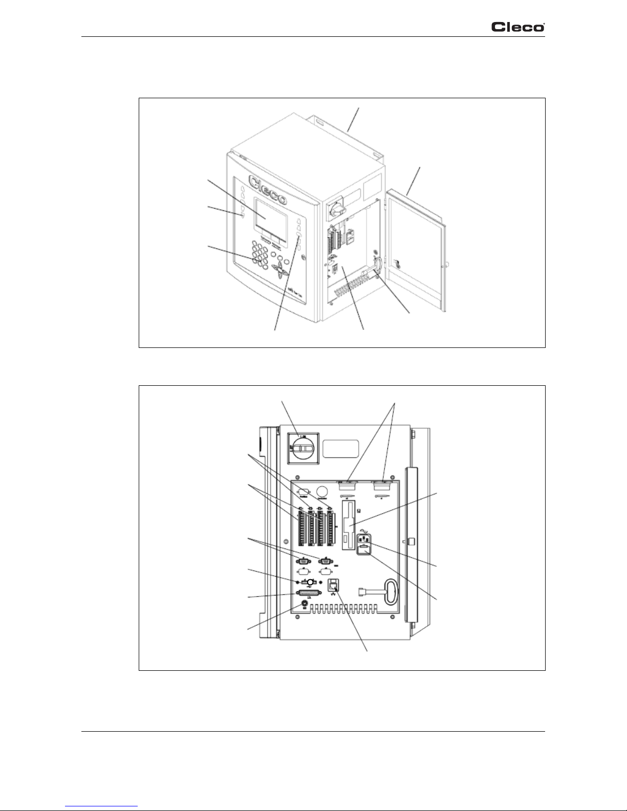
Attachment A.1
Mounting Plate
Side Door Assembly
Connector Panel
Enclosure Key
(542818)
Indicator Lights
Keypad
Indicator Lights
LCD Display
a00254_1.bmp
Fig. 1-4: Controller
.1 .1
Tool Connectors
Floppy Drive
Power In
Fuse Holder
Ethernet Port
Keyboard Port
Printer Port
USB Port
Serial Ports
I/O Inputs
I/O Outputs
Power Disconnect
a00255_1.bmp
Fig. 1-5: Connector Box Detail

en02d141.fm, 11.03.2008 PL12EN-1300 2008-03 13
Controller Specifications 2
2 Controller Specifications
2.1 Understanding the Keypad
The following is a brief explanation of the keypad keys. You will need to become familiar with
these keys so you can smoothly program your unit.
Soft Keys (F1-F4) - used to select functions based on the screen displayed.
ESC Key - used at any time to return back one screen or exit the edit mode.
DEL Key - used to delete a numerical value on the LCD screen.
Arrow Keys - used to move the orange highlight around the screen.
ENTER Key - used to accept an answer/value on the LCD screen.
Ships Wheel - used at any time to return to the navigator menu.
Run - used at any time to return to Run Screen.
Soft Keys
Ship´s Wheel

14 PL12EN-1300 2008-03 en02d141.fm, 11.03.2008
Controller Specifications
2
2.2 Specifications
2.2.1 Enclosure
Model Weight* Width Height Depth
lb kg in mm in mm in mm
TME 80 36.4 16.5 419.1 17.5 444.5 12.3 312.4
* Mounting plate adds weight of 7 lbs / 3.2 kg and depth of 1.62 in / 41.1 mm
• Designed for NEMA 13/IP54 rating
• Lockable front door for customer specific key requirements
• Lockable 3-phase power switch
• Side door for connector/cable protection
• Removable Mounting Plate
• Removable, fully operational internal chassis (TME-100 only)
• Conductive front door gasket and lip to meet EMI regulations
• Orange textured powder coat
2.2.2 Display
• 7.7" in Passive Matrix Color LCD Module (TME-100);
6.5" in Passive Matrix Color LCD Module (TME-200)
• 640 x 480 resolution
• CCFT backlight
• Contrast and Brightness control

en02d141.fm, 11.03.2008 PL12EN-1300 2008-03 15
Controller Specifications 2
2.2.3 Keypad Overlay
Key Definitions
Key Description
0-9 Numbers 0-9
.Decimal point
DEL Delete
ESC Escape
Navigator Menu
RUN Run Screen
Up Arrow
Down Arrow
Left Arrow
Right Arrow
ENTER Enter
Orange Border 4 Soft Keys
2.2.4 Indicators
5 Highly visible indicators
• 2 red groupings
• 1 green grouping
• 2 amber groupings
• Each grouping contains 12 high intensity LED´s @ 30 mcd each
2.2.5 CPU with PC 104
Minimum Requirements
• Pentium 166 Mhz
• 32 MB DRAM
• 32 MB DiskonChip
• 2 serial ports
• 1 parallel port
• Ethernet 100-Base T
• PC Keyboard input
• PC/104 Bus
• Floppy interface
• LCD/Flat Panel controller

16 PL12EN-1300 2008-03 en02d141.fm, 11.03.2008
Controller Specifications
2
Arcnet PC/104 board
• Arcnet communication
• 4 +24 V inputs
• 12 +24 V outputs
• 24-position keypad decoder
• Battery-Backed SRAM, 1 MB
External I/O PC/104 board
• 8 optically isolated inputs
• 8 relay outputs
2.2.6 AC Input Power
• Selectable 115 VAC @15 A or 230 VAC @ 10 A, +/-5% on all voltages. External fuse should
be slow blow.
• Internal fuse
• Fault current circuit-breaker (10 mA)
• Isolation Transformer 4.5 kVA peak, meets VDA 0570 norm
Note: If necessary it's possible to connect two units to one 230 VAC power supply with a 16 A
slow blow fuse (C-Type).
2.2.7 Inernal DC Power
• Input: 85 VAC-264 VAC
• Output: +5 VDC @ 5 A, +12 VDC @ 1 A, +24 VDC @ 3 A, +/-5% on all voltages
• 110 W capability without a fan
• MTBF->20,000 hours
2.2.8 Input / Output Connectors
Tool Connector Matrix MS83723R/2028N
Serial (2) 9-pin Male D-Shell
Parallel 25-pin Female D-Shell
Keyboard Mini 6-DIN
Inputs (+24 V) Phoenix MSTBV 2,5/12-GF-5,08 Order No. 1777170
Outputs Phoenix ICV 2,5/12-GF-5,08 Order No. 1825792
Floppy 3.5in 1.44 MB
AC Power Input Standard male receptacle
AC Power Output Standard female receptacle

Tool
Pin # Description Value
1+Excitation +12 V +/- .05 V
2-Excitation 0 V
3+ Torque signal 0 to +5 V
40 V Torque signal 0 V
5Tool Memory TXD - -3 V to +3 V
6Tool Memory TXD + -3 V to +3 V
7Tool Memory RXD - -3 V to +3 V
8Tool Memory RXD + -3 V to +3 V
9Resolver Carrier R1 7 VAC
10 Resolver Carrier R2 0 VAC
11 Resolver Cosine S1 7 VAC
12 Red LED 0 to +24 V
13 Signal GND 0 V
14 Yellow LED 0 to +24 V
15 Motor PE 0 V
16 Start Switch 0 to +24 V
17 Reverse Switch 0 to +24 V
18 +24V +24 V
19 Motor Phase C 0 to 300 V
20 Transducer Calibration 0 to +5 V
21 Temperature Sensor + 0 to +5 V
22 Temperature Sensor - 0 to +5 V
23 Motor Phase B 0 to 300 V
24 Resolver Sine + S2 7 VAC
25 Resolver Cosine S3 0 VAC
26 Resolver Sine S4 0 VAC
27 Motor Phase A 0 to 300 V
28 Green LED 0 to +24 V
Housing PE 0 V
en02d141.fm, 11.03.2008 PL12EN-1300 2008-03 17
Controller Specifications 2
Serial
Pin # Description Value
1DCD -25 V to +25 V
2RxD -25 V to +25 V
3TxD -25 V to +25 V
4DTR -25 V to +25 V
5GND 0 V
6DSR -25 V to +25 V
7RTS -25 V to +25 V

18 PL12EN-1300 2008-03 en02d141.fm, 11.03.2008
Controller Specifications
2
8CTS -25 V to +25 V
9RI -25 V to +25 V
Parallel
Pin # Description Value
1Strobe 0 to +5 V
2Data 0 0 to +5 V
3Data 1 0 to +5 V
4Data 2 0 to +5 V
5Data 3 0 to +5 V
6Data 4 0 to +5 V
7Data 5 0 to +5 V
8Data 6 0 to +5 V
9Data 7 0 to +5 V
10 Acknowledge 0 to +5 V
11 Busy 0 to +5 V
12 Paper Out 0 to +5 V
13 Select Out 0 to +5 V
14 Auto Feed 0 to +5 V
15 Error 0 to +5 V
16 Initialize 0 to +5 V
17 Select In 0 to +5 V
18 Gnd 0 V
19 Gnd 0 V
20 Gnd 0 V
21 Gnd 0 V
22 Gnd 0 V
23 Gnd 0 V
24 Gnd 0 V
25 Gnd 0 V
Keyboard
Pin # Description Value
1Data 0 to +5 V
2 N/C N/A
3Gnd 0 V
4Power 0 to +5 V
5Clock 0 to +5 V
Serial

Inputs
Pin # Description Value
1+24 V (Output) +24 VDC
2Input 0 0 to +24 V
3Input 1 0 to +24 V
4Input 2 0 to +24 V
5Input 3 0 to +24 V
6Input 4 0 to +24 V
7Input 5 0 to +24 V
8Input 6 0 to +24 V
9Input 7 0 to +24 V
10 Input Common (Input) 0 V
11 Signal Gnd (Output) 0 V
12 Spare N/A
en02d141.fm, 11.03.2008 PL12EN-1300 2008-03 19
Controller Specifications 2
For signal description please see chapter 3.4.2 Advanced Application Builder / Inputs, page 41.
Outputs
Pin # Description Value
1+24 V (Output) +24 VDC
2Output Common (Output) 0 to 30 V
3Output 0 0 to 30 V
4Output 1 0 to 30 V
5Output 2 0 to 30 V
6Output 3 0 to 30 V
7Output 4 0 to 30 V
8Output 5 0 to 30 V
9Output 6 0 to 30 V
10 Output 7 0 to 30 V
11 Signal Gnd (Output) 0 V
12 Spare N/A
For signal description please see chapter 3.4.3 Advanced Application Builder / Outputs, page 43.

20 PL12EN-1300 2008-03 en02d141.fm, 11.03.2008
Controller Specifications
2
This manual suits for next models
1
Table of contents
Other Cleco Controllers manuals

Cleco
Cleco mPro300GCD-STO User manual

Cleco
Cleco DGD mPro400GC User manual

Cleco
Cleco mPro400GCD-P Guide

Cleco
Cleco mPro400GCD-S User manual

Cleco
Cleco DGD mPro400GC Owner's manual

Cleco
Cleco DGD mPro400GC Guide

Cleco
Cleco mPro400GCD-P Guide

Cleco
Cleco DGD mPro400GC User manual

Cleco
Cleco CellCore 200 Series Guide

Cleco
Cleco mPro400GCD-M User manual


