CLIMA POD PASSION User manual

Contact Information:
MODULAR ORGANICS LLC
Phone: 360-674-2642
Website: www.climapod.com
PASSION Greenhouse
ASSEMBLY INSTRUCTIONS
TO BE USED IN CONJUNCTION WITH
PASSION A9 SERIES GREENHOUSE

2
Statement
Dear Customer!
We would like to congratulate you on your new Greenhouse purchase.
We hope that by following the detailed assembly instructions you will find as much pleasure in assembly process
same as the time you will spend in your greenhouse in the future.
The assembly instructions mainly consist of detailed illustrations and no specific technical knowledge is required
for the assembly of the greenhouse.
Depending on the model & accessories package you purchased you may have received multiple packages. The
main ClimaPod house (not counting in accessories or extended models) has three main master packages:
- Straight Frame & Base
- Panels
- Curved Frame
7’ Extension Set also come in three different packages.
The aluminum base, straight frame profiles, as well as supporting hardware are packed in one carton. The
greenhouse curved frames or “arches”are packed in a curved shape package.
All the polycarbonate panels are packed in one carton.
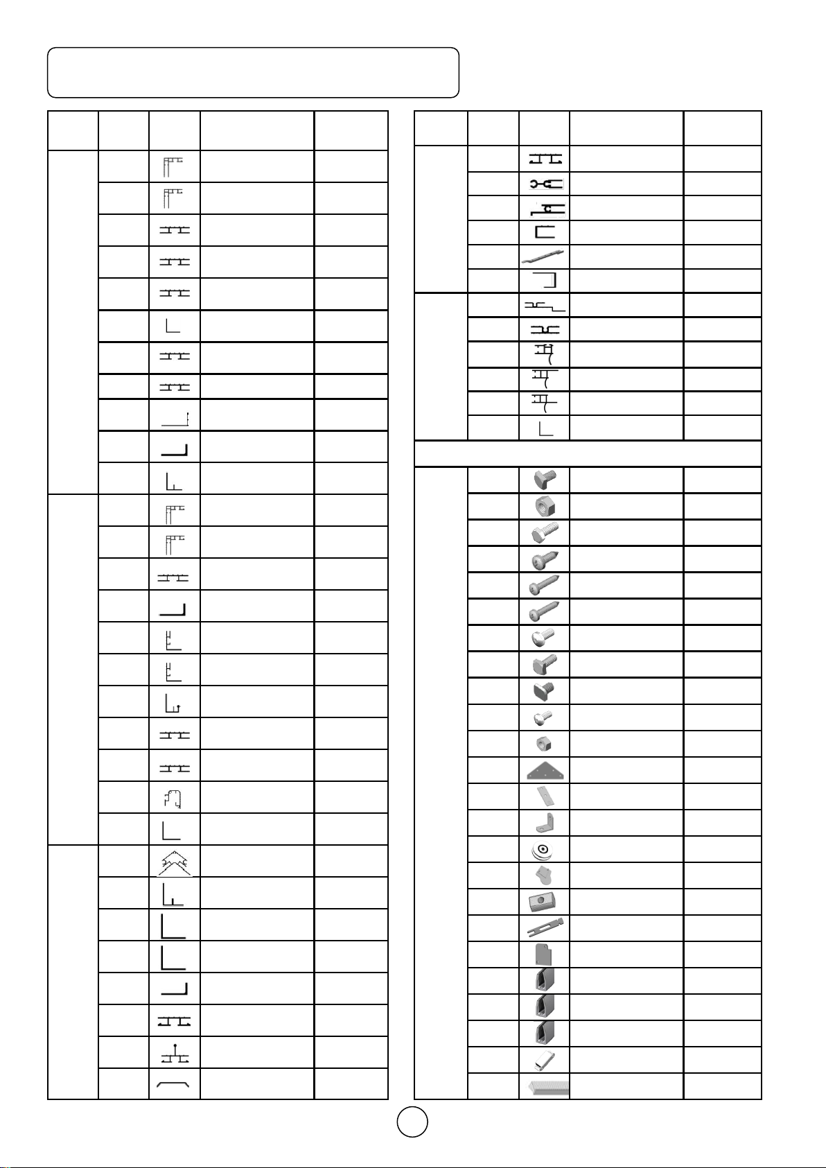
All of the aluminum profiles are marked with a part number corresponding to the numbers given on the draw-
ings and listed on the parts list. Nuts, bolts, and fittings will be found in the relevant package.
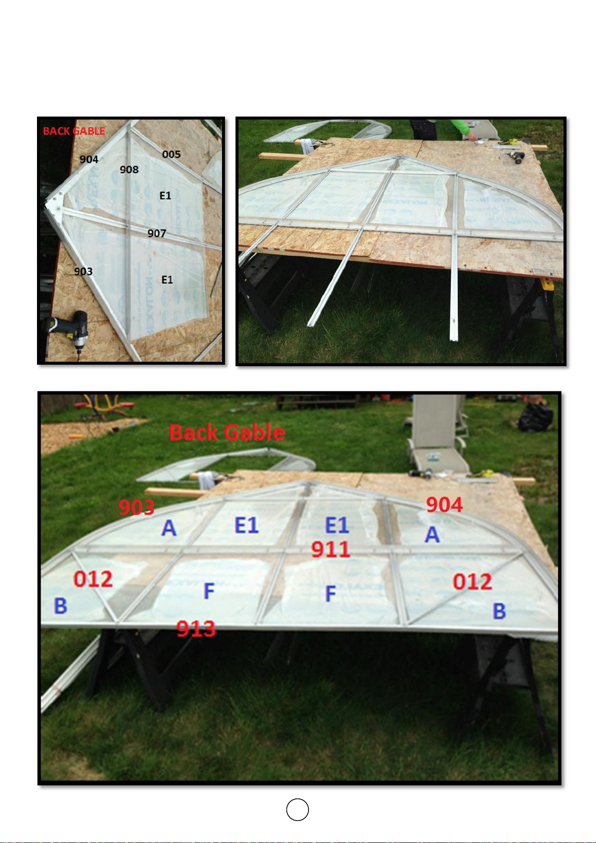
All of the rear gable section straight frames are in package No.1
All of the front gable section straight frames are in package No.2
All of the roof/side wall section straight frames are in package No.3
All of the frames and components for the window are in package No.4
All of the frames and components for the door are in package No.5
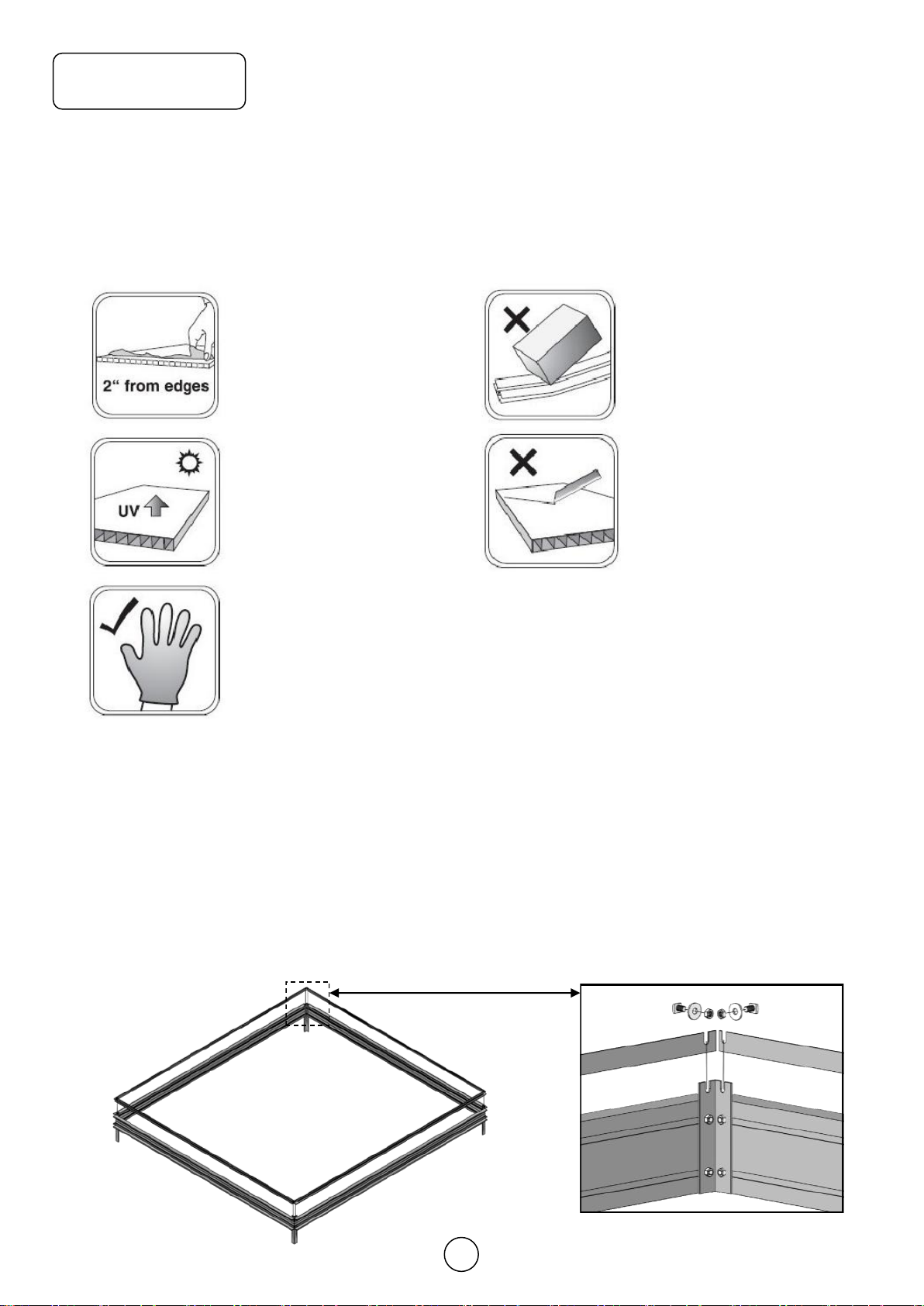
Each of the polycarbonate panels have are labeled with item number corresponding to the instructions. You
may also differentiate them by their size and shape. Note: once you get to insert the polycarbonate panels,
make sure to have the side with opal white film facing outside.
Accessories
Modular Organics LCC (ClimaPod) offers a wide range of accessories which contribute to a better yield and
make life easier for the gardener. A selection of the range is shown in the supplements to these instructions. Upon
the request, your local dealer mayprovide you with more information about available accessories. You mayalso
refer to our main website www.ClimaPod.com for more information.
Winter Protection
In areas where snow might be expected we recommend the following in order to protect your green- house:
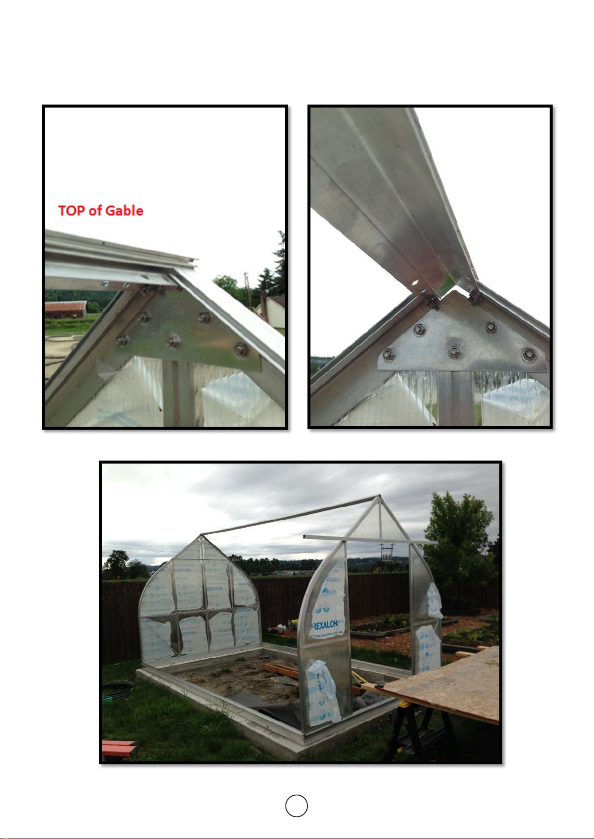
1. Support the ridge at the center of the greenhouse.
2. Remove larger snow loads by sliding them down the sides.
3. Take precautions against snow falling down.
Complaints
Weput severe demands on quality to secure that you get a faultless product. However, should a problem occur,
we kindly ask you to contact the dealer from whom you have bought the greenhouse. For a quick service, you
should specify the extent of the defect by means of the parts list in the assembly instructions. Please
also note to mention the model number which is marked on the front page of these instructions.
Guarantee
Wegrant a 10 year comprehensive guarantee which covers replacement or repairs of defective parts due to ma-
terial or manufacturing defect. The guarantee does not cover polycarbonate, transport, erection. The guarantee
is invalid if the greenhouse is not assembled according to these instructions.
Insurance
Not all insurance companies automatically cover greenhouses.We strongly recommend you contact your insur-
ance agent to ensure that your greenhouse is added to the coverage once assembled.

3
Statement
Tips
1. The base has to be fastened in a non-freezing depth(80cm).
2. The greenhouse is to be fastened to the base.
3. The base has to be 100% level and square. The easiest way to ensure this is to make sure that the
two diagonal measurements are identical.
4. We recommend that you grease screws for doors and windows for easier assembly.
5. Erection of the greenhouse should only take place in calm and dry weather.
6. All frames are to be assembled around the polycarbonate as shown on the drawings. We recom-
mend that you start with the back gable.
7. IMPORTANT Before assembling aluminum base, the end trough centers of four legs should match
both end trough centers of side sills and front & rear sills at the same time.
Remove approximately 2
inches of film from all
sheet edges before in-
stalling. Remove all film
immediately after the con-
structions is completed.
The UV-protected side of
the sheet is covered with
opal white film/text and
must face towards the
sun.
Please put on gloves
avoid slitting your hands.
Handle with care! Drop-
ping can bend the frame,
and it won’t fit properly.
Keep sharp instruments
away from the polycar-
bonate sheets.
Cautions
Foundation
The base is maintenance free and, of course all fittings are included. If you plan to use concrete foundation, re-
member to order concrete pipes and concrete at your local supply stores as they are not included with your or-
der.
Please match four corner
troughs together at the
same time
side sills
front & rear sills

4
ClimaPod Assembly Tips and Tricks
Tools required:
●10mm nut driver
●10mm open-end wrench
●Phillips head and flat head screwdriver
●Level
●Ladder
●Needle nose pliers
Misc. Items required:
●WD-40 lubricant
●Silicone Caulking Sealant
Henry 212 All Purpose Crystal Clear Sealant (recommended)
Caulking Increases the structural integrity of the greenhouse and prevents water from going into
the panels. Caulking the top of the middle seam will prevent algae and water buildup.
●The base has to be 100% level and square.
The easiest way to ensure this is to make surethat the two diagonal measurements are identical.
●Erection of the greenhouse should only take place in calm and dry weather.
●Pre-assemble and caulk windows and doors before you erect the greenhouse
●Pre-thread aluminum profiles for window and door pieces to make assembly
easier
●Keep bolts loose during assembly and avoid securely attaching side
supporting aluminum strips (ref. #012 and/or #056 strips on the parts page) before
the first panel arch has been inserted
●It is far easier to assemble if you have an elevated surface such as two 4’×8’
pieces of plywood on sawhorses.

5
Basic Steps for Assembly
1. Prepare Foundation
2. Attach and secure Base and side sills
3. Assemble and Caulk Windows and Doors
4. Assemble Gables
5. Attach Gables to base and side sills and connect with top ridge beam
6. Connect Hanging basket bar, horizontal rails, and partially connect #012
strips
7. On one side begin by inserting B panel, then crossbar, then I1 Panel
8. Secure into place with curved aluminum profile.
9. Continue the process while alternating sides.
10. When fitting final polycarbonate panels, loosen bolts to partially disconnect
front gable. It will allow you to get extra space needed for fit the last panel.
11. Slide in the windows, if necessary trim upper corners of the arches
12. Install doors and additional accessories
13. Silicone caulk panel edges on the outside all around greenhouse

6
Supplementary Instructions
Gather all parts
necessary for as-
sembling the top of
the gable.
Make sure to in-
sert Polycarbonate
pieces into Alumi-
num profiles be-
fore inserting bolts
into channels
Once bolts are in-
serted slightly
tighten nuts, at the
top, working down-
ward to position
and bolt the rest of
the gable.
The completed top of the gable should look like the image on the above.
or call 360.674.2642

7
Repeat the steps on the rear gable and continue inserting the rest of the polycarbonate
pieces and aluminum support pieces.

8
Once both gables are completed, insert them into the aluminum base and connect to the
main roof beam ridge pole (ref. #A021)

9
ClimaPod Passion Series
9x42 (A942) = one A907 Main set + five A9 7’ Extension sets
9x35 (A935) = one A907 Main set + four A9 7’ Extension sets
9x28 (A928) = one A907 Main set + three A9 7’ Extension sets
9x21 (A921) = one A907 Main set + two A9 7’ Extension sets
9x14 (A914) = one A907 Main set + one A9 7’ Extension set

10
Section Part
No. Profile Size Passion
A907
R
E
A
R
A903 2960 (9’89/16”) 1
A904 2960 (9’89/16”) 1
A005 1912 (6’31/4”) 1
A006 1912 (6’31/4”) 1
A907 2377 (7’99/16”) 1
908 1268 (4’115/16”) 1
A009 683 (2’27/8”) 2
A010 594 (1’113/8”) 2
911 2662 (8’813/16”) 1
012 1100 (3’75/16”) 2
A913 2662 (8’813/16”) 1
F
R
O
N
T
A903 2960 (9’89/16”) 1
A904 2960 (9’89/16”) 1
A009 683 (2’27/8”) 2
012 1100 (3’75/16”) 2
A014 1912 (6’31/4”) 1
A015 1912 (6’31/4”) 1
A916 2662 (8’813/16”) 1
A917 460 (1’61/8”) 1
A918 1220 (4’1/16”) 1
A919 2484 (8’113/16”) 1
056 707 (2’313/16”) 2
A021 2197(7' 2 1/2" ) 1
R
O
O
F
/
S
I
D
E
A026 2176(7' 1 11/16" ) 2
031 2163(7' 1 3/16" ) 2
036 2163(7' 1 3/16" ) 2
012 1100 (3’75/16”) 8
A042 683 (2’27/8”) 6
A943 2954 (9’85/16”) 4
955 400 (1’33/4”) 2
Section Part
No. Profile Size Passion
A907
V
E
N
T
A042 683 (2’27/8”) 2
A044 698 (2’31/2”) 2
A045 698 (2’31/2”) 2
A946 750 (2’51/2”) 4
047 300 (1113/16”) 2
048 200 (77/8”) 2
D
O
O
R
A049 586 (1’111/16”) 2
A050 586 (1’111/16”) 4
A051 1864 (6’13/8”) 2
A952 1864 (6’13/8”) 1
A953 1864 (6’13/8”) 1
054 558 (1’915/16”) 2
a1 M6x10 106
a2 M6 119
a3 M6x18 3
a4 Φ4.2x9.5 8
a5 Φ3.5x19 12
a6 Φ3.5x35 12
a7 Φ4x8 4
a8 M6x15 6
a9 M6x15
crop 4
a10 Φ3x5 4
a11 M3 4
m1 -2
m3 -5
m6 -2
n1 -4
p1 -2
p3 -4
p4 -4
p5 -2
p6 592 (1’115/16”) 2
p7 682 (2’27/8”) 6
p8 660 (2’2”) 4
m11 -1
FLUFF 3.8m 1
Passion 9x7(A907) Parts list This list includes parts count for the main
house 9’ x 7’ which includes parts for front and
back gables. Please see page 29 for 9’ x 7’ ex-
tension set parts list.

11
Polycarbonate sheet
# Size Passion
A907
A700x1049 (2’39/16” x 3’55/16”) 4
B700x842 (2’39/16” x 2’91/8”) 10
C1 602x487/16 (1’1111/16” x 1’73/16” / 5/8”) 2
D599x913 (1’119/16” x 2’1115/16”) 4
E1 610x1534/1057 (2’ x 5’3/8” / 3’55/8”) 2
F610x842 (2’ x 2’91/8”) 2
G1 700x1330 (2’39/16” x 4’43/8”) 2
H1 696x731 (2’33/8” x 2’43/4”) 2
I1 700x2110 (2’39/16” x 6’111/16”) 4
p6 592 (1’115/16”) 2
p7 682 (2’27/8”) 6
p8 660 (2’2”) 4
I1 G1 AA
A
A
D
D
B
B
BB
E1
F
H1
C1
p6p8 p8
p8
p8
p7
p6/p7/p8
p6/p7/p8
BBB
E1
F
p6
C1
D
D
I1
p7 p7
Frame Panel
Bracing bar
Note: If panel edge can’t enter into alumi-
num Frame channel, please use a
bracing bar to squeeze panel edge
into channel.
This page shows the positioning of the polycarbonate panels for the front and rear gable as
well as the roof and the sides. It also indicates where the gray plastic parts #P6, #P7 and #P8
are used. When fitting parts #P6/P7/P8 on the ends of the panels, try using a narrow piece of
bar soap through the part first. It will allow them to slide on the panel’s edges much easier.
#P6/P7/P8 must be fitted on one end of polycarbonate in advance before polycarbonate is in-
serted into aluminum frame. The square illustration on the page shows the placement of the
gray plastic U shape strips.

12
Step 1
a2
m7
Base
crop bolts/a2
Model Side profiles Anchor leg Fixing tab Crop boltsBolts/nuts WasherGable profiles
A907 2x2174(7’19/16”) 4916 25 982x2664(8’87/8”)
EXT-3 2x2148(7’9/16”) 4416 20 48-
Aluminum Base
A907 BASE
EXT-3 BASE
EXT-3 BASE
A907 BASE
Note:
For 7’ main house (9x7), 16 pcs square bolts and nuts
used for 4 legs, you need to insert into base channel in
advance. 9 pcs cropped head bolts and nuts used for
base fixing connector #m7. (no need to insert in advance)
For each 7’ Extension set that would build the size you
ordered, 16 pcs square bolts and nuts used for 4 legs,
you need to insert into base channel in advance. 4 pcs
cropped head bolts and nuts used for base fixing connec-
tor #m7. (no need to insert in advance)

13
# m5
A907 13
EXT-3 6
a2
m5
Concrete
Base
Part No. m5 shows a bracket used to secure the inside base when not using the original supplier’s foundation.
Prior to the assembly of the greenhouse, you should have a 10 mm nut driver, 10 mm open-end wrench, Philips
head and slotted screw driver, level, and WD-40 lubricant.
Assembly without base (on concrete slab or wooden deck)

14
1
A005 A006 A907 908 A009 911 012 A913 m1 a1 a2A903 A904
Part
No. p6 p8A010 p1a9
1912
6’31/4”
1912
6’31/4”
2377
7’99/16”
1268
4’115/16”
683
2’27/8”
2662
8’813/16”
1100
3’75/16”
2662
8’813/16”-M6x10 M6
2960
9’89/16”
2960
9’89/16”
Size 592
1’115/16”
660
2’2”
594
1’113/8”-M6x15
11112121124 2611Qty 22212
908
AA
E1
BB
F
2
34
5
Rear Gable
With this page, you will assemble the rear gable (back). It is far easier if you have an elevated surface
such as two 4’×8’ pieces of plywood on a sawhorses. If not, lay the aluminum profiles out on a hard sur-
face as shown in the main illustration. Remember you are building from the inside with the outside facing
down. Start with one of the “E1” panels and build the aluminum around the polycarbonate panel. the
polycarbonate side with the opal film/text must facing down.
Package No.1
A005 A006
A903 A904
A009 A010 A009
911
012012
A913
6
E1
A907
F
A010
Step 2

15
2
1Square No.1 This
the Ridge. The
square headed bolt
slides into the chan-
nel in part #A903 &
#A904, and connect
them with part #m1,
Our bolts and nuts
were made of
stainless steel.
Square No.2 Insert part #A005 into
Part #A903 channel, contact with part
#908 together, Please insert extra bolt
#a1 into the channel of Part #A005 for
attaching part #911 use later. Do the
same for the opposite end.
A904A903
m1
908
A005
A903
A907
Note: Please connect Part #911 with Part #A903, #A904, #A005, #A006,#A907
firstly before you are inserting PC panel #A &#E1 into profiles’ channel.
3A
Square No.3 After PC
panels in position, then
dismantle part #911 and
adjust the distance same
between PC panel and
keyway edge.
A903
911
A009
012
911
A903
A
A009
A903 A904
908
911
A006A005
AA
A009 A009A010
AA
E1
A907
E1
E1
E1
A010
a9 Section View
A009
a9 a9 is a
cropped
head
bolt

16
4
BBF
5
Square No. 5
Inserting PC panel
#B,#F in profiles’
channel. With PVC
anti-dust strip #p6
& #p8 on bottom.
Square No.6
Connect Part
#A913.
Please note: 4 Bolts will need to be slid into each Part #A903 and #A904 for ridge, hanging basket bar or horizontal rail
and side sill beam in advance, Finger tightens the nuts for later use.(Bolts and nuts in Package No.3 of Roof/Side wall)
When finished with the back gable, position and securing away from the wind so it does not blow over and cause damage.
Square No. 4 Assembly part #A009, #A010 in place, then connect with part #911 again.
911 A010
911
A009
p8
A913
p8 p6 p8
A913
p6
F
Please Note: Don’t let this bolt block polycarbonate panel to
insert into part #A903&A904 alu. frame channel. Insert PC panel
first, then slide this bolt in part #A903&A904 profile’s trough.
A903 A904 A903
6
p6
A913
p8
012

17
Front Gable Package No.2
Square No.1
this step is
very much like
the rear gable.
``
A009 012 A014 A015 A916 A917 A918 A919 m1 m3 a1A903 A904
Part
No. a2 a3 p8p1a9056
683
2’27/8”
1100
3’75/16”
1912
6’31/4”
1912
6’31/4”
2662
8’813/16”
460
1’61/8”
1220
4’1/16”
2484
8’113/16”--
M6x10
2960
9’89/16”
2960
9’89/16”
Size M6
M6x18
660
2’2”
-
M6x15
707
2’313/16”
22111111111811Qty 23 32122
1
A904A903
m1
A917
AA
BB
A009 A009
A903 A904
012 012
A916
A014 A015
A918
A919
C1
1
4
6
7
5
3
C1
A917
2
056 056
Step 3

18
Square No.3
Assemble
polycarbonate
panel #C1 on
part
#A903,#A917,
#A904, use
part #A918 to
fix it.
C1
A918
3
A918
A904
A015
a3
C1
2
A918
A917
a3
m3
A903 A904
A903 A904
AA
A009 A009
4A904
A009
Square No.4 Af-
ter PC panels in
position, then adjust
the distance to same
between PC panel
and keyway edge. a9
Section View
A009
a9 is a
cropped
head
bolt
a9
5A014 A009 Square No.5 Use
the part #056 to con-
nect the part #A009
& #A014.
056
056
012
a9
A904

19
Please note: 4 Bolts will need to be slid into each Part #A903 and #A904 for Ridge, hanging basket bar or horizontal rail
and Side sill beam in advance, Finger tightens the nuts for later use.(Bolts and nuts in Package No.3 of Roof/Side wall)
Square No.8 The bolt #a3 to fix #A918 is an extra
long stainless bolt. The bolt slides into part #A919 and
extends through parts #A903 & #A904.
A919
a3 A919
a3
B
p8
B
p8
6A904
A916
p8
8
Section view
A918
Square No. 6
Inserting PC panel
#B in profiles’
channel. With PVC
anti-dust strip #p8
on bottom.
Square No.7
Connect Part
#A916.
Please Note: Don’t let this bolt block polycarbonate panel to in-
sert into part #A903&A904 alu. frame channel. Insert PC panel
first, then slide this bolt in part #A903&A904 profile’s trough.
A903 A904
A916
7
p8
A916
012
A014

20
Step 4 Passion 7’ Extension (A9 EXT A-Frame)
Part No. A943 961 962 m1 a1 a2 a8
Size 2954
(9’85/16”) 2921
(9’7”) 850
(2’97/16”) -M6x10 M6 M6x15
Qty 2211614 8
A943 A943961 961
962
1
2
3
4
5
123
45
A943
961
a8/a2
15mm
A943
961
a8/a2 A943
961
a8/a2
961
A943
962
a1/a2 A943 A943
961 961
a1/a2
a8/a2
Please connectA943 glazing bar first
(on both sides), then have T-shape 961
connection bar go over the A943 (on the
inside).
Please Note: The bottom end part of
T-shape 961 bar is not connected to
the base and should be secured
15mm (~5/8 inch) shorter (see image
1). This is very important.
Table of contents
Other CLIMA POD Greenhouse Kit manuals