www.cls-led.com www.cls-led.com
7 8
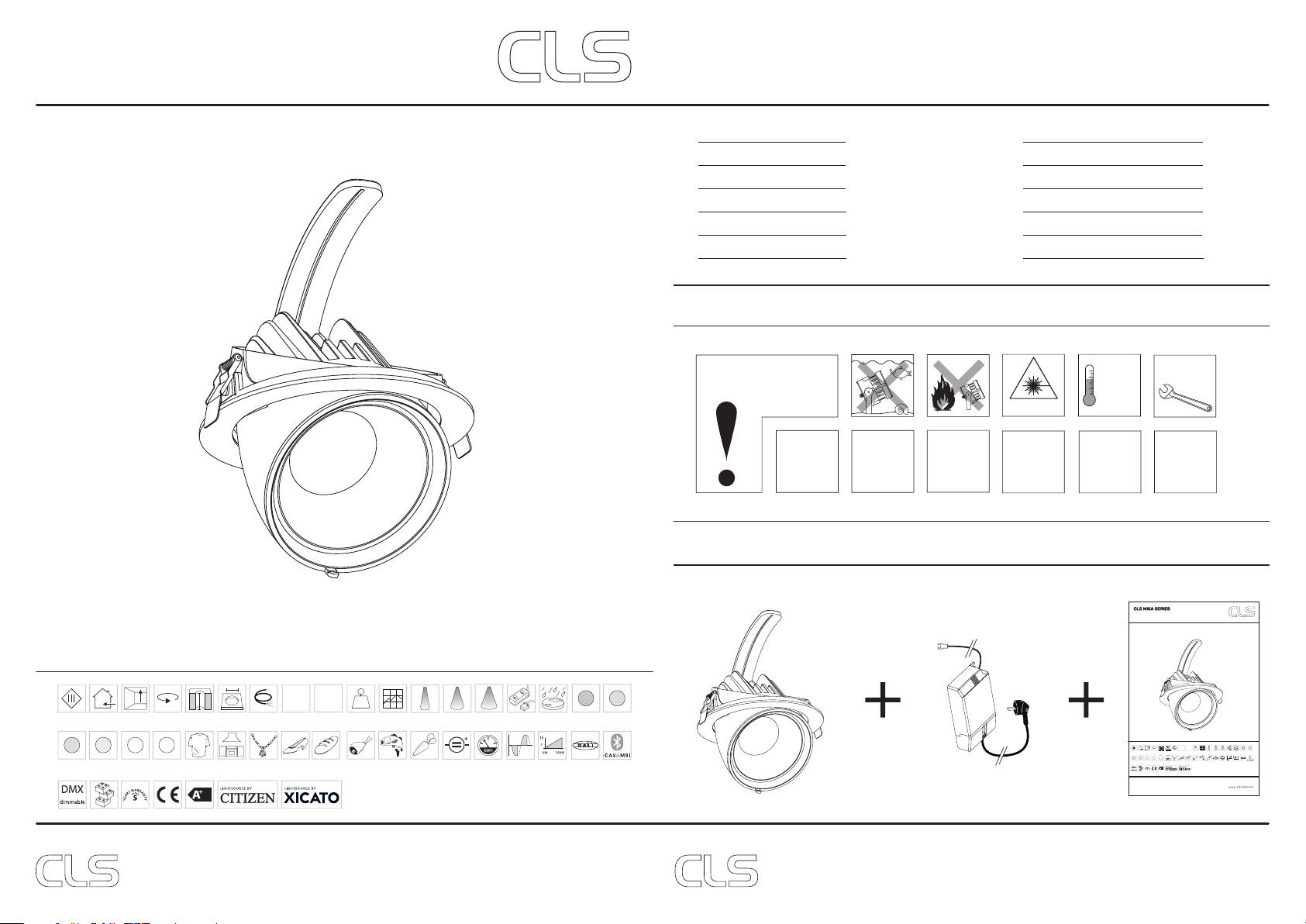
LIST OF SYMBOLS
Multiple connection
Daisychain connectivity
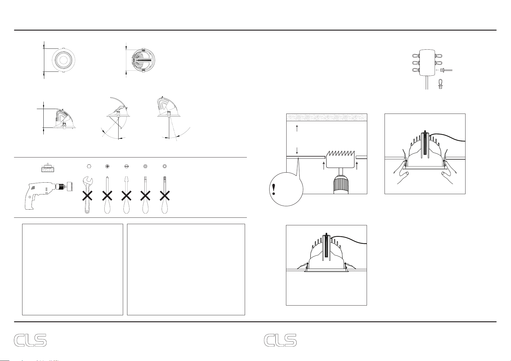
Installation depth
In centimeters
Swivel
Fixture is horizontally rotatable,
indicated in degrees
Swivel
Fixture is vertically rotatable,
indicated in degrees
Installation size
In centimeters
Application area
Indoor or outdoor
Application area
Floor, wall or ceiling
Protection class
One, two or three
Cable length
Maximum cable attached
to the fixture in centimeters
Lifespan
Of the light source in hours
Driver
Inclusive or exclusive
Internal or external
Pressure
Maximum pressure on the
fixture in kg/cm2
Weight
In grams/kilograms
Curve
Minimal bending curve
in centimeters
LED pitch
Pitch between the LEDs
in millimeters
Power supply
In VDC, VAC or milliAmpere
Power consumption
In VA or Watt
IP value
Ingress Protection classifies the
degrees of protection provided against
the intrusion of the product
Cutting length
Indicated by the cutting
marks
LEDs
Kind of LED used in the
fixture
Lenses
Availble lenses,
indicated in degrees
Performance Zoom
Adjustable beam angle
Plug & play
Easy connection using the
SmartConnect system
White colour temperature
In dierent Kelvin values;
Cold white, neutral white, warm
white or extra warm white
Colour
Available colours;
Amber, blue, red or green
Colour changing
RGB, RGB-W, RGB-A,
AWB or Tunable White
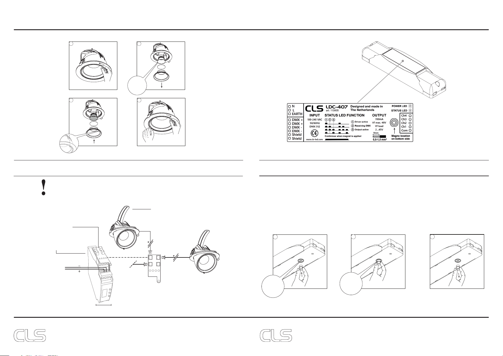
DMX input
Fixture works on DMX512
protocol or Wireless DMX
Magno dimming
Accurate dimming from
100 - 1% by using a magnet
Dynamic Control
Dynamic Power Control or
Dynamic Temperature Control
Combined product
Compose your own fixture
Warranty
3 or 5 years warranty on
the product
Energy label
Conformité Européenne
CE marking for free marketability
of industrial goods within the EU
r
h
ø w d
Dimmable
1-10 Volt, Phase, individual,
DMX dimmable or DALI
DRIVER
INCLUDED
DRIVER
EXTERNAL
Retail & Food LED modules
Clothing, furniture, kitchens, jewellery,
shoes, bread, meat, fish and
vegetables & fruit.
Lightsource
Equipped with a CLS, Citizen or a Xicato
LED module
Bluetooth controlled
By Casambi
PWM dimming
Traditional PWM dimming, DMX analog
or DMX Hybrid dim
CLS
DYNAMIC
COLOUR
COB
CH1
001to255
UsethisDMXchanneltosetaddressfrom001to
255.TheconfiguredDMXaddressiscalled“n”
CH2
UsethisDMXchanneltosetaddressfrom256to
508.TheconfiguredDMXaddressiscalled“n”
CH3 Static
behavior
IfnoDMXispresentthefixturewillrespondlike
setinthisfunction.
CH4 Softdim
SoftdimwillinterpolatebetweentheDMX
values.Thisfunctionmakesthedimcurve
CH5 Master
control
Ifmasterisfirstchannelisselectedthechannel
willbeDMXchannel“n”.Ifmasterislastchannel
isselectedthechannelwillbe“n+x”
(“x”iscalculatedintheoutputpatch).
CH6 Output1
patch
Eachoutputchannelcanbepatchedtorespond
tothedesiredDMXchannel.Thisenablesthe
usertomixupthecoloursaccordingtothe
controllerthatisused.
Example:alloutputsarepatchedas1
AlloutputswillbecontrolledbyDMXchannel
“n”.IfmasterisusedtotalDMXchannelswillbe2
otherwiseituses1channel(“x”=1).
Example:output1&2arepatchedas1and3&4
arepatchedas2
Output1&2willbecontrolledbyDMXchannel
“n”.
Output3&4willbecontrolledbyDMXchannel
“n+1”.
IfmasterisusedtotalDMXchannelswillbe3
otherwiseituses2channels(“x”=2).
CH7Output2
patch
CH8 Output3
patch
CH9Output4
patch
CH10Staticoutput
1
Eachoutputchannelcanbesettoanstatic
intensity.
IfnoDMXispresentandStaticbehaviorissetto
“loadstaticvalues”.Theoutputswillbesettothe
configuredintensityvalues.
CH11Staticoutput
2
CH12Staticoutput
3
CH13Staticoutput
4
CH14Loaddefault
settings
ThisfunctionresetsallsettingstotheFactory
setting.CheckFactorysettingtable.
X
LoadFactorysettings.Xisrow
numberfactorysettingtable.
PROGRAMMING TABLE