CMP TYPE TMC2 CABLE GLAND FOR USE WITH INTERLOCKED & CORRUGATED
CONTINUOUSLY WELDED METAL CLAD (TYPE MC OR MC-HL) OR TECK ARMORED AND
ARMORED & JACKETED CABLES IN ORDINARY, WET & HAZARDOUS LOCATIONS.
INCORPORATING EU DECLARATION OF CONFORMITY TO DIRECTIVE 2014/34/EU
TECHNICAL DATA EXPLOSIVE ATMOSPHERES CLASSIFICATION
INSTALLATION GUIDANCE NOTES
1. In accordance with NEC requirements, glands with NPT and Metric entry threads are suitable for both Divisions and Zones.
2. In accordance with CEC requirements, glands with NPT threads are suitable for both Divisions and Zones. Glands with Metric threads are only suitable for Zones unless fitted with an approved Metric
to NPT thread conversion adaptor.
CMP Products Limited on its sole responsibility declares that the equpement referred to herein conforms to the requirements of the ATEX Directive 2014/34/EU and the following standards:
EN 60079-0:2009, EN 60079-7:2007, EN 60079-21:2009, BS 6121:1989, EN 62444:2013
David Willcock - Certification Engineer - (Authorised Person)
CMP Products, Cramlington, NE23 1WH, UK
24th June 2015
CABLE GLAND
TYPE TMC2
INSTALLATION INSTRUCTIONS FOR
CMP CABLE GLAND TYPE TMC2
ACCESSORIES
1. The following accessories are available from CMP Products, as optional extras, to assist with fixing, sealing and earthing: Locknut | Earth Tag | Serrated Washer
Glasshouse Street • St. Peters • Newcastle upon Tyne • NE6 1BS
Tel: +44 191 265 7411 • Fax: +44 1670 715 646
Notified Body: Sira Certification Service, Unit 6, Hawarden Industrial Park, Hawarden, CH5 3US
0518
CABLE GLAND TYPE : TMC2
INGRESS PROTECTION : IP66, NEMA 4X
PROCESS CONTROL SYSTEM : BS EN ISO 9001
: ISO/IEC 80079-34:2011
ATEX CERTIFICATION No : SIRA 09ATEX1164X
ATEX CERTIFICATION CODE : ^II 2GD, Ex e IIC Gb, Ex ta IIIC Da
IECEx CERTIFICATION No : IECEx SIR.09.0068X
IECEx CERTIFICATION CODE : Ex e IIC Gb, Ex ta IIIC Da
cCSAus CERTIFICATION No : 2194053
CSAus CERTIFICATION CODE : Class II, Groups E,F and G; Class III; Enclosure type 4X;
1. Entry component threads may need additional sealing to maintain the ingress protection rating as applicable to the associated equipment in which it will be attached.
2. The cable ranges shall only be used where the temperature, at the point of entry, is in the following ranges -60°C to +110°C.
SPECIAL CONDITIONS FOR SAFE USE
Logo’s shown for illustration purposes only. Please check certification for details
SCAN FOR INSTALLATION VIDEOS
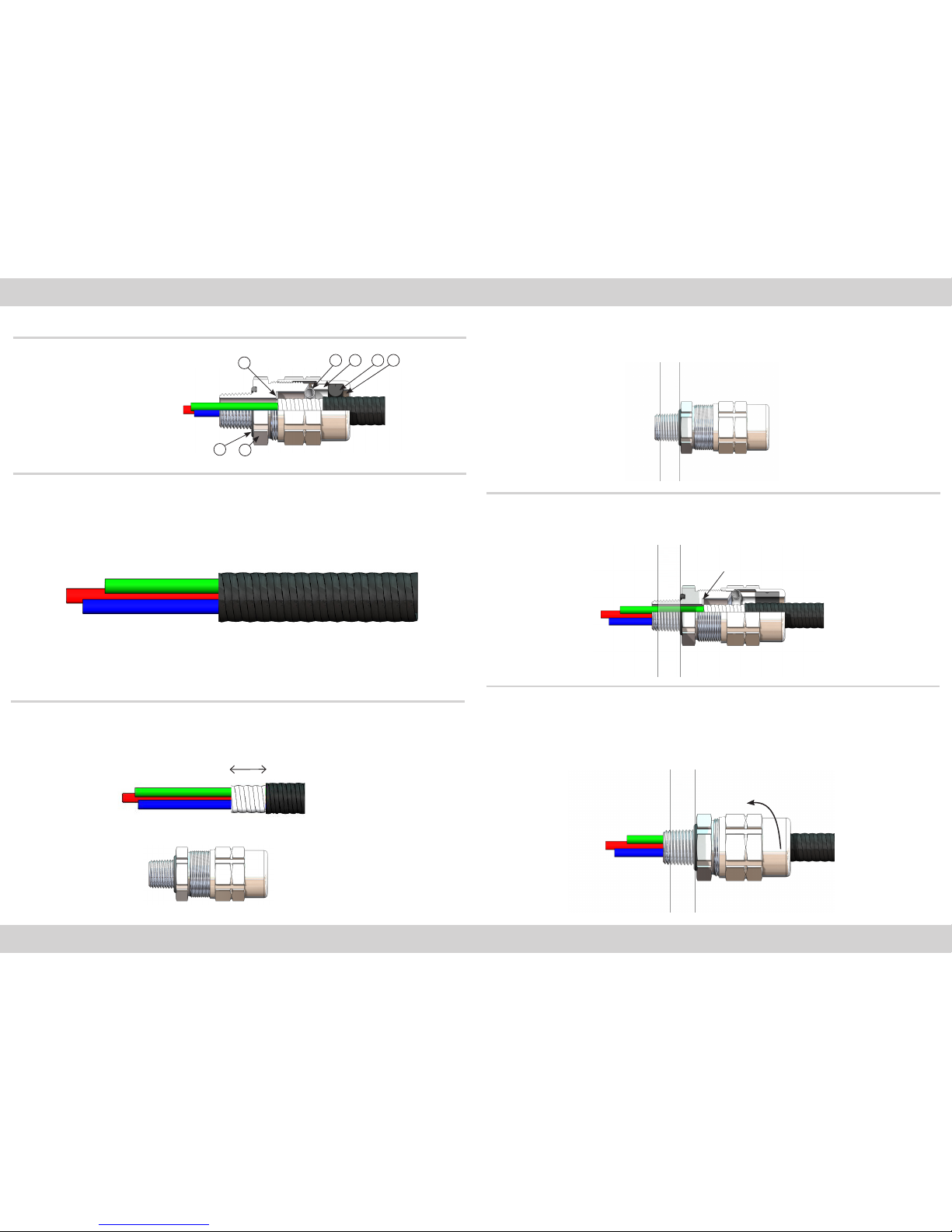
INSTALLATION INSTRUCTIONS
Installation should only be performed by a competent person using the correct tools. Read all instructions before beginning installation.
TMC2-M20A075 TMC2-M20NB075 TMC2-M20SS075 M20 -15.0 10.67 13.97 13.97 16.00 12.70 19.05 13.00 30.48 33.53 61.98 PVC06 0.065
TMC2-M25A075 TMC2-M25NB075 TMC2-M25SS075 -M25 15.0 10.67 13.97 13.97 16.00 13.00
TMC2-M20A099 TMC2-M20NB099 TMC2-M20SS099 M20 -15.0 15.24 16 .51 16 .51 22.61 17.53 25.15 15.49 37.59 41. 35 75.11 PVC09 0.085
TMC2-M25A099 TMC2-M25NB099 TMC2-M25SS099 -M25 15.0 15.24 19.81 19.81 22.61 19.00
TMC 2-M25 A118 TMC2-M25NB118 T MC2- M 25SS118 M25 -15.0 20.07 21.8 4 21.84 27. 9 4 22.10 29.97 20.80 45.97 50.57 8 0 .11 P VC11 0.145
TMC 2-M32 A118 TMC 2-M32 N B11 8 TMC2-M32SS118 -M32 15.0 20.07 24.89 24.89 2 7.94 24.00
TM C2- M32 A137 TMC2- M32NB137 TMC2-M32SS137 M32 -15.0 23.88 2 7.43 27.43 32. 51 25.91 34.80 26.44 52.07 5 7. 28 90.09 PVC15 0 .19 0
TM C2- M40A137 TMC2-M40NB137 TMC2-M40SS137 -M40 15.0 23.88 29.97 29.97 32.51 28.88
TM C2- M40A162 TMC2-M40NB162 TMC2-M40SS162 M40 -15.0 30.99 34.29 34.29 38.10 33.02 41.15 33.20 59.94 65.94 91.21 P VC18 0.250
TM C2- M50 A162 TMC2-M50NB162 TMC2- M50SS162 -M50 15.0 30.99 36.07 36.07 3 8.10 34.98
TM C2- M40A190 TMC2-M40NB190 TMC2-M40SS190 M40 -15.0 - - 38.35 43.69 39.88 48.26 34.80 65.02 71.53 91.11 PVC37 0.268
TM C2- M50 A19 0 TMC2-M50NB190 TM C2-M50SS190 -M50 15.0 - - 38.35 43.69 38.99
TMC2-M50A200 TMC2-M50NB200 TMC2-M50SS200 M50 -15.0 39.88 4 3.18 43.18 47.75 41.91 50.80 41.0 0 69.85 76.83 95.40 PVC21 0.314
TMC2-M63A200 TMC2-M63NB200 TMC2-M63SS200 -M63 15.0 39.88 4 3.18 43.18 47.75 41.99
TMC2-M50A233 TMC2-M50NB233 TMC2-M50SS233 -M50 15.0 - - 45.97 5 6 .13
48 .51 59 .18
41.00
74.93 82.42 100.89 PVC23 0.362TMC2-M63A233 TMC2-M63NB233 TMC2-M63SS233 M63 -15.0 - - 45.97 5 6 .13 51. 49
TMC2-M75A233 TMC2-M75NB233 TMC2-M75SS233 -M75 15.0 - - 45.97 5 6.13 51. 49
TMC2-M63A272 TMC2-M63NB272 TMC2-M63SS272 -M63 15 .0 54.36 62.48 55.12 66.29
57. 6 6 69.09
52.53
89.92 98.91 104.09 PVC28 0.70 0TMC2-M75A272 TMC2-M75NB272 TMC2-M75SS272 M75 -15. 0 54.36 62.48 62.48 66.29 60.99
TMC2-M90A272 TMC2-M90NB272 TMC2-M90SS272 -M90 24.0 54.36 62.48 62.48 66.29 60.99
TMC2-M90A325 TMC2-M90NB325 TMC2-M90SS325 M90 -24.0 63.25 70.61 70.61 75.44 66.55 82.55 68.96 10 9.98 120.9 8 118 . 4 9 PVC32 1.210
TMC2-M100A 325 TMC2-M100NB325 TMC2-M100SS325 -M100 24.0 63.25 70.61 70. 61 75.44 68.96
TMC2-M100A 376 TMC2-M100NB376 TMC2-M100SS376 M100 -24.0 74.93 87.6 3 8 7. 63 89.92 80.26 95.50 85.95 12 2.94 135.23 125.81 LSF33 1.515
TMC 2-M115A376 TMC2-M115NB376 TMC2-M115SS376 -M115 24.0 74.93 87. 6 3 8 7.63 89.92 85.95
TMC 2-M115A425 TMC2-M115NB425 TMC2 - M115SS42 5 M115 -24.0 - - 90.42 100.08 93.98 107.9 5 91.26 132.84 14 6 .13 131.09 LSF34 1.678
METRIC Dimensions above are displayed in millimetres unless otherwise stated
Order Reference
(NPT suffix required) Entry Thread
Minimum
Thread
Length
Cable Armor Diameter Cable Jacket
Diameter
Thru
Bore
Across
Flats
Across
Corners Nominal
Assembly
Length
Shroud
Approx
Weight
Aluminum
(Ozs)
NPT
Standard
NPT
Option
Aluminum Nickel Plated Brass Stainless Steel
Armor Stop
In Armor Stop Out Min Max Max Max Max
Min Max Min Max
TMC2-050A075 TMC2-050NB075 TMC2- 050SS075 1/2” -0.78 0.42 0.55 0.55 0.63 0.50 0.75 0.51 1.20 1.32 2.44 PVC06 2.29
TMC2-075A075 TMC2-075NB075 TMC2-075SS075 -3/4” 0.80 0.42 0.55 0.55 0.63 0.51
TMC2-050A099 TMC2-050NB099 TMC2-050SS099 1/2” -0.78 0.60 0.65 0.65 0.89 0.69 0.99 0.61 1.48 1.63 2.96 PVC09 3.00
TMC2-075A099 TMC2-075NB099 TMC2-075SS099 -3/4” 0.80 0.60 0.78 0.78 0.89 0.75
TMC2-075A118 TMC2-075NB118 TMC2-075SS118 3/4” -0.80 0.79 0.86 0.86 1.10 0.87 1.18 0.82 1.81 1.99 3.15 PVC11 5.11
TM C2-10 0 A118 TMC2-100NB118 TM C2-10 0 S S118 -1” 0.98 0.79 0.98 0.98 1.10 0.95
TM C2-10 0 A137 TMC2-100NB137 TMC2-100SS137 1” -0.98 0.94 1.08 1.0 8 1.28 1.02 1.37 1.04 2.05 2.26 3.55 PVC15 6.70
TM C2-125A137 TMC2-125NB137 TMC2-125SS137 -1-1/4” 1.01 0.94 1.18 1.18 1.28 1.14
TM C2-125A162 TMC2-125NB162 TMC 2-125SS162 1-1/4” -1.01 1.22 1.35 1.35 1.50 1.30 1.62 1.31 2.36 2.60 3.59 PVC18 8.82
TM C2-15 0A162 TMC2-150NB162 TMC2-150S S16 2 -1-1/2” 1.03 1.22 1.42 1.42 1.5 0 1.38
TM C2-125A190 TMC2-125NB190 TMC2-125SS19 0 1-1/4” -1.01 - - 1.51 1.72 1.57 1.90 1.37 2.56 2.82 3.59 PVC37 9.45
TM C2-15 0A190 TMC2-150NB190 TM C2-15 0SS190 -1-1/ 2” 1.03 - - 1.51 1.72 1.54
TMC2-150A200 TMC2-150NB200 TMC2-150SS200 1-1/2” -1.03 1.57 1.70 1.70 1.88 1.65 2.00 1.61 2.75 3.03 3.76 PVC21 11.0 6
TMC2-200A200 TMC2-200NB200 TMC2-200SS200 -2” 1.06 1.57 1.70 1.70 1. 88 1.65
TM C2-15 0A233 TMC2-150NB233 TMC 2-150 SS2 33 -1-1/ 2” 1.03 - - 1.81 2.21
1.90 2.33
1.61
2.95 3.25 3.97 PVC23 12.7 7TMC2-200A233 TMC2-200NB233 TMC2-200SS233 2” -1.06 - - 1.81 2.21 2.03
TMC2-250A233 TMC2-250NB233 TMC2-250SS2 33 -2-1/2” 1.57 - - 1.81 2.21 2.03
TMC2-200A272 TMC2-200NB272 TMC2-200SS272 -2” 1.06 2 .14 2.46 2.17 2.61
2.27 2.72
2.07
3.54 3.89 4 .10 PVC28 24.69TMC2-250A272 TMC2-250NB272 TMC2-250SS272 2-1/2” -1.57 2.14 2.46 2.46 2.61 2.40
TMC2-300A 272 TMC2-300NB272 TMC2-300SS272 -3” 1.63 2.14 2.46 2.46 2.61 2.40
TMC2-300A 325 TMC2-300NB325 TMC2-300SS325 3” -1.63 2.49 2.78 2.78 2.97 2.62 3.25 2.72 4.33 4.76 4.67 PVC32 42.68
TMC2-350A325 TMC2-350NB325 TMC2-350SS325 -3 -1/ 2” 1.69 2.49 2.78 2.78 2.97 2.72
TMC2-350A376 TMC2-350NB376 TMC2-350SS376 3-1/2” -1.69 2.95 3.45 3.45 3.54 3.16 3.76 3.38 4.84 5.32 4.95 LSF33 53.44
TMC2-400A376 TMC2-400NB376 TMC2-400SS376 -4” 1.73 2.95 3.45 3.45 3.54 3.38
TMC2-400A425 TMC2-400NB425 TMC2-400SS425 4” -1.73 - - 3.56 3.94 3.70 4.25 3.59 5.23 5.75 5.16 LSF34 59.19
Dimensions are displayed in inches unless otherwise stated
cCSA CERTIFICATION CODE : Class I, Div 2, Groups A, B, C and D; Class II, Groups E,F and
Class I, Zone 1,AEx e II, AEx ta IIC ; Ex e II
G; Class III Enclosure type 4X; Ex e II ; Class I, Zone 1 AEx
e II , AEx ta IIC
FI410
Revision
Reason
Revision
Number
Revision
Date
IFS 12 11/09/2018
ATEX / IECEx - -
CSA / cCSAus - -
UL - -