CNB AN802IR User manual

Contents
2 3
260x COLOR VIDEO CAMERA
COLOR VIDEO CAMERA
POWER ZOOM
260x
DAY&NIGHT
INSTRUCTION MANUAL
WDR COLOR VIDEO CAMERA
with DAY & NIGHT
Thank you for purchasing a CNB Zoom Camera.
This manual describes how to install and operate your CNB Zoom Camera.
Before installation, familiarize yourself with all features and precautions of this product.
After installation, keep this manual handy for future reference.
This manual applies to the following model.:
CNB-AN802IR
①Brand
②Product
③Signal System
④Model
⑤Option
⑥
Communication System
⑦Infrared LED
①Brand
GSDCT DIGIOP
powered by CNB
②Product
A ZOOM camera
③Signal System
N NTSC
P PAL
⑤Option
0 D&N enabled
1 D&N disabled
5 Normal Resolution
⑥Communication System
0 For Pan/Tilt zoom controller
1 RS-232C
2 RS-422
④Model
8 26x camera
2 22x camera
3 12x camera
⑦Infrared LED
IR Infrared LED included
L Disital Slow Shutter
Features
User Information
Safety and Precautions
Rear view and Part Names
Installation
On-Screen Display
Menus and Operations
Specifications
1.
2.
3.
4.
5.
6.
7.
8.
4
5
6
7
8
14
16
37
P/N : 3810-0025A
PRINTED IN KOREA
Head office;
#501, Kolon Techno Valley, 60-4
Gasan-Dong Geumcheon-Gu,
Seoul, Korea 153-770
http://www.cnbtec.com

260x COLOR VIDEO CAMERA260x COLOR VIDEO CAMERA
4 5
6 7
1. Features
260x COLOR VIDEO CAMERA260x COLOR VIDEO CAMERA
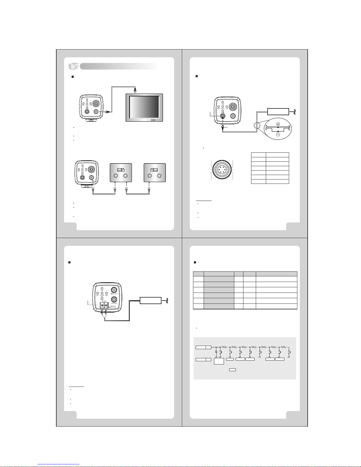
4. Rear View and Part Names
3. Safety and Precautions
2. User Information
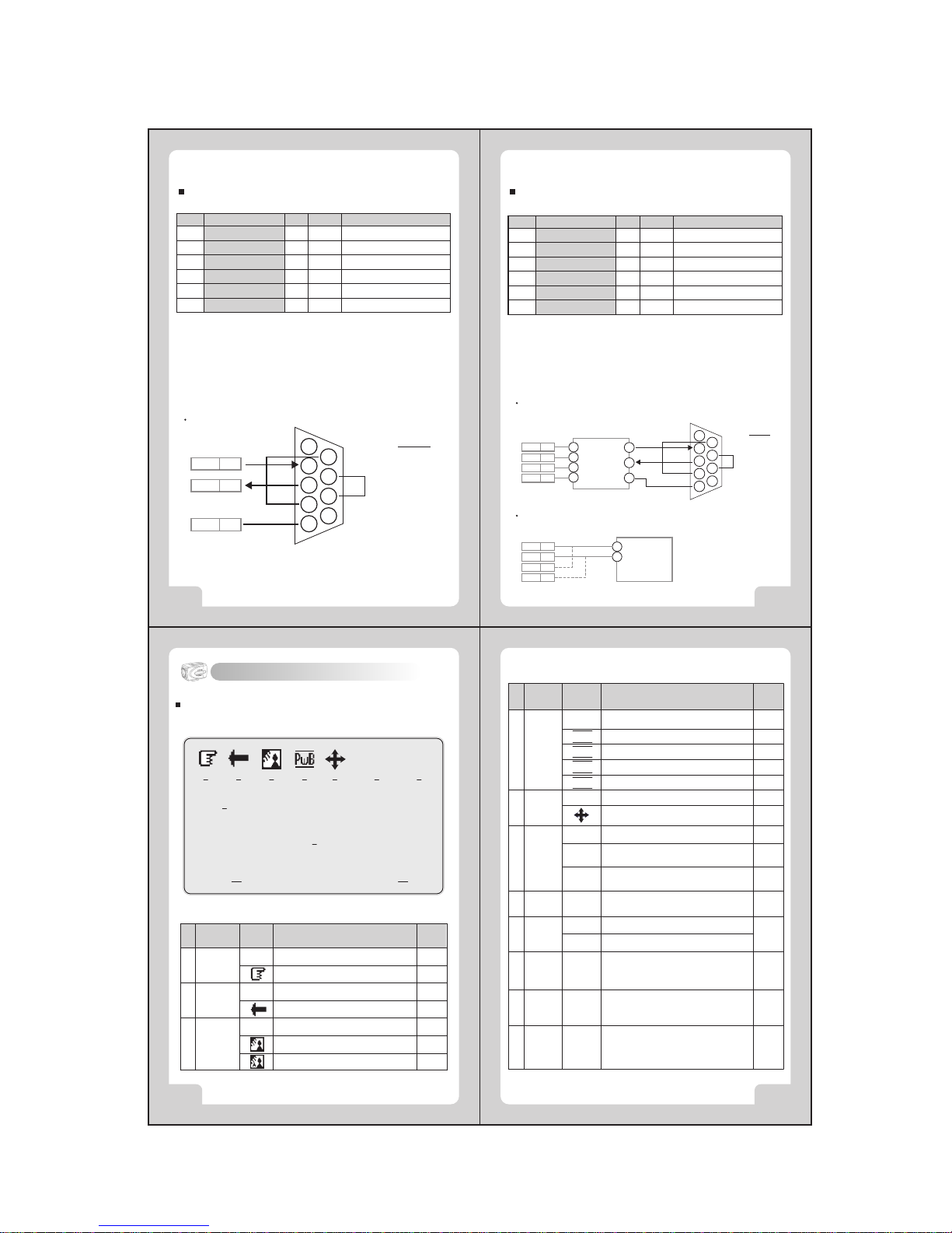
4. Convenient setup of function using menu
All camera operations can be controlled with the MENU buttons.
2. Day & Night function
It automatically judges whether it is day or night to deiver the best
pictures. Color pictures are provided during the day black and white
pictures at night. A separate infrared ray LED is unnecessary since
the built-in IR LED is used when the IR Cut Filter is removed at night.
- IR LED can be turned on or turned off in OSD MENU.
- IR LED is a model-specific option.
Caution: When using a glass housing, select a model without IR LED.
Problems may occur on the screen when the infrared ray
reflects off the housing glass.
3. High-Magnification Zoom function
Subjects can be magnified up to 260 times with the 26x optical zoom
and 10x digital zoom.
1. High-Resolution and High-Definition picture
Provides high-definition picture 480 TV line horizontal resolution,
with 1/4 inch SONY Super HAD CCD.
WARNING- TO PREVENT ELECTRIC SHOCK AND RISK OF FIRE HAZARDS,
DO NOT EXPOSE THIS APPLIANCE TO RAIN OR MOISTURE.
INFORMATION
This equipment has been tested and found to comply with limits for a
Class A digital device, pursuant to part 15 of the FCC Rules.
These limits are designed to provide reasonable protection against
harmful interference when the equipment is operated in a commercial
environment.
This equipment generates, uses, and can radiate radio frequency energy
and, if not installed and used in accordance with the instruction manual,
may cause harmful interference to radio communications.
Operation of this equipment in a residential area is likely to cause
harmful interference in which case the user will be required to correct
the interference at his own expense.
WARNING
The manufacturer could void the user's authority to operate the
equipment.
CAUTION- To prevent electric shock and risk of fire hazards:
Do NOT use power sources except for that specified.
Do NOT expose this appliance to rain or moisture.
This installation should be made by a qualified service person
and should be confirmed to all local codes.
Avoid using the camera in extreme temperature environments.
Using the camera in temperatures exceeding 50˚C or below -10˚C may
lessen picture quality or cause the camera to malfunction.
Avoid using the camera in high humidity environments.
Using the camera in places with high humidity may lessen picture quality
because of moisture on the lens.
Avoid using the camera in unsteady lighting.
The camera will not work properly in places with great changes in
illumination intensity, such as fluorescent lamps.
Make sure no foreign substances get on the front glass of the camera.
Do not disassemble the camera and prevent foreign substances
from getting into the camera.
Make sure that the camera is not exposed to an intense light source
such as direct sunlight.
It may damage the CCD.
Camera may be damaged if dropped or subjected to strong impact.
Keep camera dry.
The camera will be damaged if immersed in water.
Avoid using the camera in the presence of oil and gas.
The camera will be damaged if oil or gas penetrates the exterior.
Caution
- Smear or blooming(when bright areas spreads out) may occur when
photographing in strong light, i.e. car headlights, etc.
- Make sure that you are using a compatible power adapter(DC12V, 500mA)
before connecting it to the camera.
- When the camera is used in a glass housing, the infrared ray may reflect
off the glass.
S-VIDEO
VIDEO
POWER IN Class 2 Only
CTL
W( )
( )N F( )MENU
T( )
-+
<Controller Model>
<RS-232C/ RS-422 Communication Model>
Function
Setup Button
Power Input &
Control Terminal
S-VIDEO Output
Terminal
Video Output
Terminal
Tripod Socket
Video Out
Control Terminal
(Communications)
Power Input
Terminal

260x COLOR VIDEO CAMERA260x COLOR VIDEO CAMERA
10 11
8 9
5. Installation
Connecting to Monitor
Connect the video output terminal on the back of the product to the monitor
The method of connecting the camera to a monitor varies depending on
the model. Please refer to the manual for your model.
Connect the camera after switching off each piece of equipment.
Change the 75Ω/Hi-Z conversion switch of each piece of equipment
according to the following diagram- move the switch of the intermediate
video receiver to Hi-Z, and the end equipment to 75Ω.
S-VIDEO
VIDEO
POWER IN Class 2 Only
CTL
Camera Monitor
Connect the S-Video terminal to a color monitor.
Connect the camera's S-Video output to the monitor's S-Video input
terminal using the S-Video cable.
Set the monitor's S-Video 75Ωswitch to ON.
S-VIDEO
VIDEO
POWER IN Class 2 Only
CTL
75ΩHi-Z
VIDEO
IN OUT
75ΩHi-Z
VIDEO
IN OUT
End EquipmentCamera Intermediate
Video Receiver
S-VIDEO
VIDEO
POWER IN Class 2 Only
CTL
Connecting Power (For Controller Model)
Connect Pin 5 (Black: GND) and Pin 6 (Red: DC12V) of the 6-pin connector
cable to the output of power adapter according to the following diagram.
DC12±0.5V
Power Adapter
Power Supply
6-pin Connector Cable
Pin Configuration of
6-pin Circular Connector
[6-pin Circular Connector Pins]
Pin. No.
1
2
3
4
5
6
Color
Green
White
Brown/Blue
Yellow
Black
Red
Caution
When connecting to the power source, make sure the polarity of the power
adapter is correct.
Connect power only after installation has been completed.
AC adapter is sold separately.
1
2
3
6
5
4
Connecting Power (for RS-232C/ RS-422 Communication Model)
Connect the AC adapter output to the power input terminal of the camera
according to the following diagram.
DC12±0.5V
Power Adapter
Power Supplying
Terminal
Caution
When connecting to the power source, make sure the polarity of the power
adapter is correct.
Connect power only after installation has been completed.
AC adapter is sold separately.
-+
Connecting 6-pin Connector (for Controller Model)
Pin. no. NAME I /O NoteColor
1
2
3
4
5
6
ZOOM (+:Tele, -:Wide)
FOCUS (+:Near, -:Far)
KEY
COM(For Zoom, Focus)
GND (For Power)
DC IN
Input
Input
Input
Input
Green
White
Brown
Yellow
Black
Red
±6V(Limit +3~13V, -3~-13V)
DC 12±0.5V
Link pins 1, 2, and 4 as in the above table, when using pan/tilt, zoom controller.
KEY 3
GND 5 POWER
ON/OFF
0.01uF 6.8K 8.2K 8.2K 18K 33K 68K 180K
MENU TELE(+) WIDE(-) NEGA
ON/OFF
NEAR(+) FAR(-) A/M
(P.AUTO)
: WIRE REMOTE CONTROL KEY FUNCTION
Connecting KEY:
The following KEY circuit can be configured and used.
- The 6-pin connector can be controlled by connecting the external wired
remote control
- An optional external wired remote controller is provided.
- There are two types of external wired remote controller- 1.5m and 30m.
or Blue

260x COLOR VIDEO CAMERA260x COLOR VIDEO CAMERA
12 13
14 15
6. On-Screen Display
EX. VD (Negative. 5Vp-p)
Connecting 6-pin Connector (for RS-232C Model)
1
2
3
4
5
6
Input
Output
Input
Input
Green
White
Brown
Yellow
Black
Red
+12V ~ -12V
+12V ~ -12V
- RS-232C communication model can be controlled by connecting pins
1, 2 and 4 to the PC as shown in the above table.
- The operating S/W is not provided. Configure the S/W using the protocol
provided by our company.
RD(For RS-232C)
TD(For RS-232C
KEY
GND
GND
Line IN
Connecting to PC
TD 2
RD 1
GND 4
RS-232C D-Sub Connector
1
2
3
4
5
6
7
8
9
NAME
1. Frame GND
2. RD
3. TD
4. DTR
5. Signal GND
6. DSR
7. RTS
8. CTS
9. RI
Pin. no. NAME I /O NoteColor
or Blue
Connecting 6-pin Connector (for RS-422 Model)
Input
Input
Output
Output
Input
- RS-422 communications model can be used by connecting pins 1, 2, 3 and
4 in the following diagram.
- The operating S/W is not provided. Configure the S/W using the protocol
provided by our company.
EX. VD (Negative. 5Vp-p)
R+
R
-
T+
T
-
GND
Line IN
Connecting to PC (RS-422 Communication)
R + 1
R - 2
T + 3
T - 4
Tx+
Tx-
Rx+
Rx-
RS-232C TO RS-422 Converter
RS-232C D-Sub Connector(PC)
TD
RD
Connecting to DVR (RS-485)
1
2
3
4
5
6
7
8
9
NAME
1. Frame GND
2. RD
3. TD
4. DTR
5. Signal GND
6. DSR
7. RTS
8. CTS
9. RI
TRX +
TRX -
R + 1
R - 2
T + 3
T - 4
GND
DVR(RS-485)
Pin. no. NAME I /O NoteColor
1
2
3
4
5
6
Green
White
Brown
Yellow
Black
Red
or Blue
Others
ExplanationOSDFunction
"ND" : No Display
Motion detectedMD
No motion detectedND
Motion
Detect
8
Temporary automatic mode
Outdoor mode
Indoor mode
Optical zoom : x1 ~ x26
Digital zoom: Dx27 ~ Dx260
* indicates digital zoom
x1
…
Dx260
Zoom11
Explanation of the scene capture
by the camera (max. 10 letters)
-
Zone
Label
10
Displayed when POWER ON of the
camera is in operation
WAIT
Initial
LOGO
9
Camera identification number
000 ~
255
ID7
Shutter speed indicator
X125 ~
X10000
Flicker Correction mode
Digital Panning/Tilting
Special color Correction mode
Standard shutter speed(NTSC:1/60, PAL:1/50)
ND
Shutter
Speed
6
No Act Digital Panning /TiltingND
Pan/Tilt5
Automatic color Correction modeND
White
Balance
4
‘D’
SwB
OwB
IwB
PwB
FL
.
Explanation of the On-Screen Display
The OSD (On Screen Display) is as follows:
X10000 255
WAIT
Dx260
1 2 3 4 5 6 7
9
8
Zone Label
11
MD
10
ND
Backlight3
ND
Mirror2
Automatic focus mode
Manual focus mode
No screen inverted
Screen is inverted to the left or right
Backlight Compensation off
Backlight Compensation mode
Automatic backlight Compensation mode
ND
Focus1
Others
ExplanationOSDFunction
"ND" : No Display
Other CNB IP Camera manuals