CNB MPC1050IR User manual

Rev 1.1
Network Camera
(“M” Series)
User Manual

2
Network Camera_ User manual
Revision History:
Date Rev No Description
Dec. 1th, 2013 1.0 Creation of the Document
Feb. 20th, 2014 1.1 Modified “2.7. Video etup - I P Module Adjust”
Indications:
Warning : Death or erious Injury will occur without following Warning.
Caution : Operational Problem(Faulty & Malfunction) will occur without complying with Caution.
Re erence : Technical Information for Users.

3
Network Camera_ User manual
Contents
1. PREPARATION FOR THE CONNECTION ................................................................................... 4
1.1. Product Installation .............................................................................................................. 4
1.2. PC Requirements .................................................................................................................. 6
2. CONFIGURATION IN ADMIN MODE ......................................................................................... 7
2.1. Access ................................................................................................................................. 7
2.2. Layout of the admin mode .................................................................................................... 9
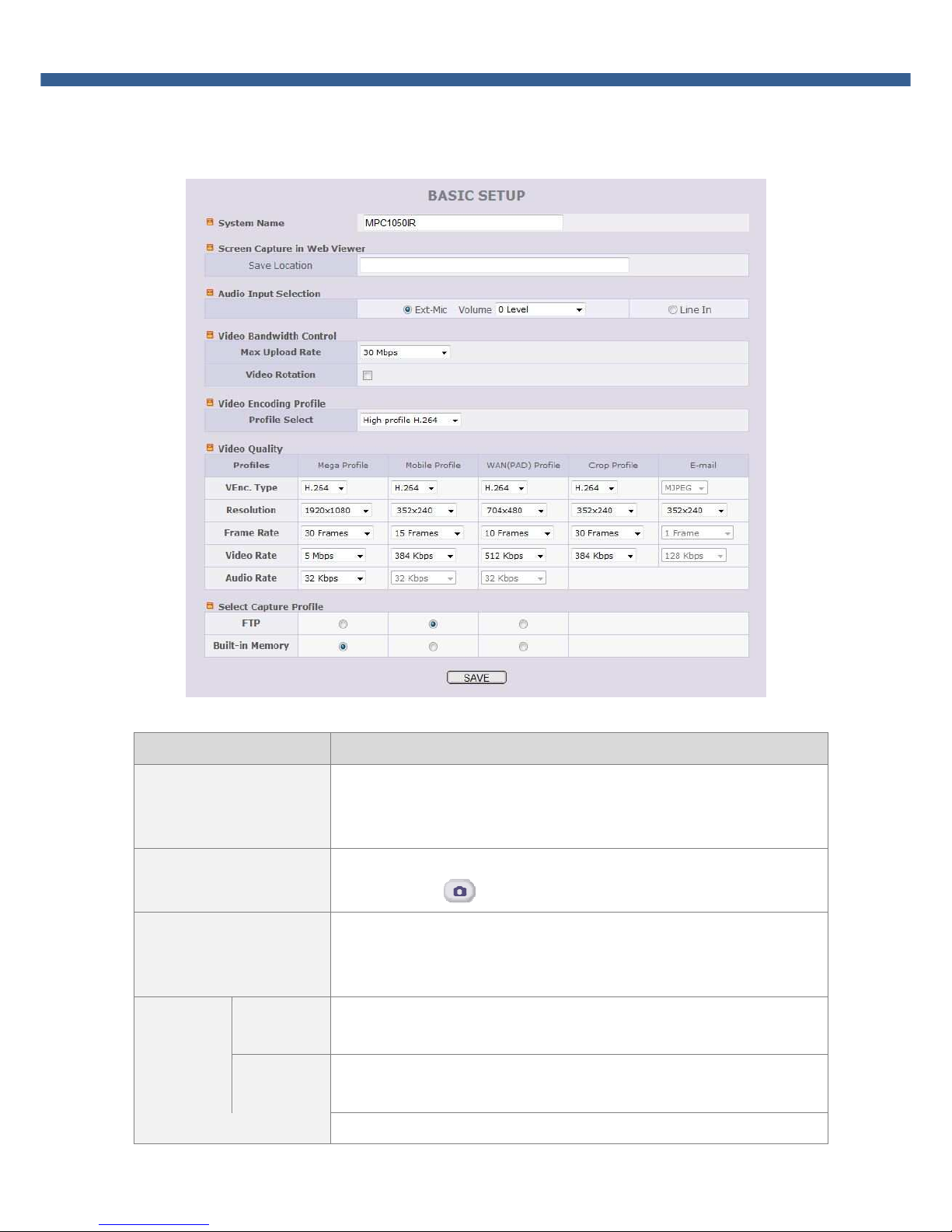
2.3. Basic etup ........................................................................................................................ 10
2.4. Network etup ................................................................................................................... 12
2.5. 802.1x etup ..................................................................................................................... 14
2.6. Onvif etup ........................................................................................................................ 15
2.7. Video etup ....................................................................................................................... 16
2.8. User Admin & Time etup ................................................................................................... 18
2.9. ensor & Capture etup ..................................................................................................... 20
2.10. E-Mail & FTP etup ............................................................................................................ 22
2.11. Alarm Device etup ............................................................................................................ 23
2.12. Motion Detection etup ...................................................................................................... 24
2.13. Audio Detection ................................................................................................................. 26
2.14. PTZ etup .......................................................................................................................... 27
2.15. Upgrade & Reset ................................................................................................................ 28
2.16. tatus Report ..................................................................................................................... 31
3. WEB VIEWER ......................................................................................................................... 32
3.1. Web Viewer ....................................................................................................................... 32
3.2. Buttons and Indicators of Web Viewer. ................................................................................ 33
3.3. Crop Video etting ............................................................................................................. 34
3.4. PTZ Control Menu .............................................................................................................. 35
4. TROUBLE SHOOTING AND TIPS ............................................................................................ 39
4.1. Trouble shooting after installation ........................................................................................ 39
4.2. Trouble shooting after successful connection to the device.................................................... 40

4
Network Camera_ User manual
1. Preparation for the connection
1.1. Product Installation
Brief information for rapid installation is provided in this section. For more detailed information you are
recommended to refer to pertinent documentations provided with the product.
1. Apply Power to the product and connect the product with network cable.
Applying improper power to device can cause damage to the device.
Varieties of power supplying option are provided for each of the product. Please refer
to the manual of each specific product for available option.
2. Install “IP installer (Ver.3.0.1 or above)” and “NVR-Pro (Ver.5.17 or above)” on your PC.
Each Program is included in the CD coming with product and can be downloaded from
www.cnbtec.com.
Detailed information for installing these programs can be found in [IP-Installer User’s Guide] and
[NVR-Pro User’s Guide], respectively.
3. Assign IP address to the product using IP installer IP Installer.
Identify the type of the network environment and set up IP address. Detailed process of setting up
IP address can be found in [IP-Installer User’s Guide]. If network type is xD L or Cable modem
you need supplementary information provided by your I P.

5
Network Camera_ User manual
< Quick Installation Guide o IP-Installer >
Install the IP Installer on the PC or Laptop. The WinPCap installed together is required software for the
operation of IP-Installer. Please install the WinPCap essentially as when it is not installed, IP Installer won’t
operate.
a. Starting IP-Installer.
Upon initiation of the IP-Installer, the PC will ask for the selection of proper network adaptor. Click on
proper LAN or WIFI network interface module displayed to highlight the selection and click on “OK”
to start the program.
b. Find the product or the con iguration
Click on “Re resh” button to find the list of the products (IP cameras or video servers) connected on
the same subnet as the PC.
]
Fig. 1-1. IP-Installer Product Search
c. Assign network parameters needed or connection to the product. Please ollow through
the ollowing procedures.
i. Double click on a product you want to set up.
ii. Once the parameter Fields as shown Fig 1-2 are activated, set the network parameters.
iii. Once you fill in the fields, click on “Set” to initialize the product with new settings.

6
Network Camera_ User manual
Fig. 1-2. IP-Installer Parameter Setting Up
1.2. PC Requirements
AV streaming data received from IP camera or video server can be decoded or stored in a PC running
NVR-PRO program or other CM program. Minimum requirement of the PC is recommended as in the
following table.
Item Minimum Requirements Misc
CPU Intel Core i3 above
RAM 2GB
Graphic Card ATI Chip et Based, 512M above Resolution : 1920x1080 above
LAN Card 100Mbps above
O Windows XP / Windows 7

7
Network Camera_ User manual
2. Configuration in Admin Mode
The detailed operational parameters of the product can be configured through Admin Mode via network.
2.1. Access
The access to Admin Mode can be done using 2 ways; through Internet Explorer and the “NVR-Pro”
program.
1. Using Internet Explorer
Type in the connection address of the product in the address field of the Internet Explorer as
followings:
http://[IP address of the product]/admin.htm
Example : http://172.16.64.133/admin.htm
If you changed the HTTP port of the product from default value (80) you can access to Admin mode
by adding HTTP port address as the following:
http://[device IP address]:[HTTP port]/admin.htm
Example : http://172.16.64.133:8080/admin.htm
2. Using the “NVR-Pro”
elect video channel in the viewing window of “NVR-Pro”. elected video channel will be highlighted,
then Click button on the right side of the display screen to access to admin mode.
Figure 2-1. Access to admin Mode rom “NVR-Pro”

8
Network Camera_ User manual
3. Input User Name and Password in the display screen shown below.
Factory default “User Name” and “Password” are set as “root” and “admin”, respectively. Click on
“OK” button to enter into the Basic Setup page of Admin mode. If you have changed the username
and password of the Administrator, you must log on with the changed username and password.
For the sake of enhanced security, we strongly recommend you to change ID and Password
during the installation and keep the ID and Password carefully for not opening to others.
The details are described on [User Admin & Time etup] section of this document.
If ID and Password are lost, restore the factory default value by following the procedure
below.
When the power is applied to product, press the Factory Default button for more than 3 sec,
then all etting Parameters will be returned to Factory Default.

9
Network Camera_ User manual
2.2. Layout o the admin mode
Upon initiation of the admin mode, the screen similar to the following picture will be shown.
The left side of the admin page shows various admin Mode menus, while the right side shows the settings
of selected admin menu. Click each of the menu items at the left to go into specific admin mode.
Fig. 2-2. Layout o Admin Mode
elect the language of your preference from drop down list at Top-right.
Click on “Live” button for initiating live video connection after finishing Admin Mode.
The following sections describe details for each admin mode menu.

10
Network Camera_ User manual
2.3. Basic Setup
etup the basic parameters for the operation of the product.
Fig. 2-3. Basic Setup
Item Description
ystem Name
Logical name of the product. It is same as the one set-up by IP-installer.
You can reassign the logical name. The system name will be shown in the
connection through NVR-Pro.
creen Capture in Web
Viewer
Designate the folder to save captured image in Web viewer by clicking
capture button ( ). Default path is Desktop.
Audio Input election
elect the type of input audio.
Line In : used for Line-out from general audio device.
Ext-Mic : used for Microphone
Video
Bandwidth
Control
Max upload
rate
Assign maximum bandwidth of the uplink for the network connected to
device.
Video
rotation Check at the box to rotate the video by 180
o
.
Video Encoding Profile elect video encoding profile.

11
Network Camera_ User manual
Baseline : Primarily for low-cost applications like as videoconferencing and
mobile applications.
Main : Used for standard-definition digital TV broadcasts.
High : primary profile for broadcast and disc storage applications,
particularly for high-definition television applications (for example, Blu-ray
and the DVB HDTV)
elect profile for your circumstance. Default is “High pro ile”. Check
whether client supports selected profile because video can't be displayed
if client does not support selected profile.
Video
Quality
Profile
Maximum 5 different video profiles can be transmitted simultaneously
through different video channel. Define the parameters for each video
profile.
E-mail profile is only used for e-mail transmission against Event.
VEnc. Type
Assign video codec for the channel. Either H.264 or MJPEG can be chosen.
Only H.264 is allowed for Mega Profile. As the use of MJPEG can be
limited only for certain software, please check it before selecting MJPEG.
If MJPEG is selected, “Video Rate” is automatically adjusted for
configured resolution and frame rate.
Resolution
Assign the resolution of each profile.
Frame rate Assign video frame rate. You can improve picture quality by lowering
frame rate for the same bandwidth.
Video rate
Assign bandwidth for transmitting video data.
Higher the video rate ensure better video quality. But if you set the video
rate exceeding the Max. Upload peed, the normal video transmission
can’t be done. If the video is interrupted or mosaic, you need to lower the
video rate.
Audio rate Assign bandwidth for transmitting audio data. Audio data is not
transmitted if you select “NA”
elect Capture Profile
elect the video profile upon event.
Upon event, selected profile will be transmitted to FTP erver or stored in
(micro) D Card.
AVE ave the set-up parameters when parameters settings are finished.
You must click the “ ave” once you finish all settings.
Remarks In case of 5mega pixel camera, the resolution is shown differently at the
mega profile.

12
Network Camera_ User manual
2.4. Network Setup
etup the network parameters appropriately in accordance with your network environment. Many of the
parameters in this mode are same as those set up by “IP-Installer”.
Fig. 2-4. Network Setup
Item Description
IP Assign
Type
The network types supported by the products are LAN(fixed IP), PPPoE, and
DHCP(automatic IP allocation).
tatic IP etup
When the network environment is fixed IP, select ‘LAN’ in the network
type, and input the IP address, ubnet Mask, Gateway, DN 1 and
DN 2. Ask your network administrator or I P for the information.
DN 2 is used when DN 1 does not work.
#. When you change the DNS, you should restart the camera
to apply the DNS.
PPPoE etup
When the network environment is PPPoE with automatic IP address
assignment, select ‘PPPoE’ in the network type and fill in the ‘User
Name’ and ‘Password’ fields with the values given by your I P. It is for
the use with AD L modem.

13
Network Camera_ User manual
DHCP etup
When the DHCP server assigns IP address automatically, select ‘DHCP’
in the network type. elect this mode in case of Cable Modem.
Refer to [IP-installer user’s guide] for “Host name and domain for
Cable Modem.
Clone MAC Refer to [IP-installer user’s guide] for “Clone MAC”.
Port Change
Port number should be positive integer below 65,535. Duplication of port number is
prohibited.
HTTP HTTP port is used for the connection to the admin mode. Default is 80.
RT P
The RT P port is used for transmitting real time audio/video data from
the product. Default is TCP 554.
RT P Address : rtsp://camera_ip_address[:rtsp_port]/ tdCh<1|2|3|4>
RTP
The RTP port is used for transmitting real time audio/video data from
the product. Default is UDP 6970. It can be might not be used in some
environment.
Multicast
The range of Multicast address is 224.0.0.0 ~ 239.255.255.255.
Address The address is used for multi-casting real time audio/video data from
the product. Default is 224.1.1.1.
Port The port is used for multi-casting real time audio/video data from the
product. Default is UDP 6970.
TTL Define number of routers multi-casting data pass through. Default is
0(off).
IP Filtering
You can restrict the access to the admin mode from IP addresses beyond certain IP
address range.
Restrict
Administrator
Access
Check at this box to restrict log on to the admin mode.
Base IP
Address
Input IP address of the PC which is intended to be used for log on to
admin mode.
DynDN
etting
You can register the product to the Management erver (DDN erver) for name
service.
Enable
DynDN
Enable / Disable DynDN .
When enabled, you can automatically obtain a domain from DDN
server by simply registering the network camera product.
DynDN
etting
Enable
Anonymous
Enable / Disable DynDN Anonymous feature.
When enabled, DDN service is used without going through
authentication at autoipset.com DDN server.

14
Network Camera_ User manual
If you want to register a hostname with a specific user account at
autoipset.com server, Please make an account from
(http://www.autoipset.com)
AVE ave the set-up parameters when parameters settings are finished.
You must click the “ ave” once you finish the all settings.
2.5. 802.1x Setup
This is setup mode for IEEE802.1x authentication.
Fig. 2-5. 802.1x Setup
Item Description
Activation Check at the box to enable 802.1x authentication. If checked, this
product behaves as a client requiring authentication..
Certificate
CA Certificate Certificate for server verification.
Client Certificate
Certificate for client verification.
Private Key Private Key of client.
etup
elect EAP type and configure ub Fields.
EAP type
elect EAP type to choose authentication method. In order for
authentication to be successful, the client and the server must use the
same authentication method. Fields used in each method are as

15
Network Camera_ User manual
etup
followings:
EAP-MD5 : Username, Password
EAP-TL : CA Certificate, Client Certificate, Private Key, Username,
Private Key Password
PEAP : CA Certificate, Username, Password
EAP-TTL : CA Certificate, Username, Password
Username Account name of client.
Password Password for the account
Private Key
Password Password for Private Key.
AVE ave the set-up parameters when parameters settings are finished.
You must click the “ ave” once you finish the all settings.
2.6. Onvi Setup
Onvif protocol is open standard for communication between network video devices. It supports camera set,
configuration, real time viewing, PTZ camera control, etc. You can interoperate the IP Camera with Onvif
tandard Compliant NVR or CM .
Authentication OFF : Camera does not require authentication for access.
Authentication ON (de ault) : Camera requires authentication for access.
Registered user accounts, including Administrator account, are used for authentication. To register
user account, please refer “2.8 User Admin & Time etup” part of this manual.

16
Network Camera_ User manual
2.7. Video Setup
You can adjust the parameters of input video. Note that parameters will vary in accordance with the
camera module employed.
Fig. 2-6. Video Setup
Item Description
Video
Control
Contrast Adjust contrast. Default is 50.
Brightness Adjust Brightness. Default is 50.
aturation Adjust saturation. Default is 50.
Hue Adjust hue. Default is 50.
Power Line
Frequency
elect frequency of the power.
Power frequency can be different by each country. Correct one must
be choose for frequency
It can be selectable 50Hz or 60Hz. Default is 60Hz.
O D Time Display
Enable/disable O D time display and allocate the position of O D
display.
Blind
Blind out some part of the video. elect the color for Blind mask. After
the color is selected, position the mouse to one corner then click and
drag the mouse to desired position and release button to select the
area.
AVE ave the settings.
Restore original values Click on “CONFIRM” to restore the default settings.
I P Module Adjust Adjust the I P module. Click to initiate..

17
Network Camera_ User manual
Fig. 2-7. ISP Module Setup
Item Description
I P
Control
WDR et the WDR mode ON or OFF.
Anti Flicker ynchronize the video frequency with Power Frequency of your
region to remove flickering. (OFF, 60Hz, 50Hz)
low FP Enhance the Video image under the low light condition by
controlling the shutter speed.
harpness Adjust the sharpness of video. The higher, the better video image.
Video can be noisier with higher value.
Auto Iris et the Auto Iris ON or OFF
2DNR et 2 dimensional noise reduction value.
3DNR et 3 dimensional noise reduction ON or OFF.
Exposure
compensation at night
et function Exposure compensation at night in accordance with
the installation environment.
For the product with default automatic function, the selection is
deactivated.
Exposure Type
Change the camera exposure type.
AUTO : The exposure value is automatically adjusted.
UTTER PRIO. : Only the shutter speed can be set and Gain value
will be adjusted automatically.
MANUAL : utter speed and Gain value can be set.
et hutter & Gain
In the case of exposure type with manual will be activated.
utter speed and Gain value can be set.
Restore original values Click on “CONFIRM” to restore the default settings.
AVE ave the settings.

18
Network Camera_ User manual
2.8. User Admin & Time Setup
You can change the ID and password of users and also assign different attributes to each user. Once the
required setting-up is finished, please click the “ ave” to save the setting values.
Fig. 2-8. User Admin. & Time Setup
Item Description
User
Administration
Administrator
Username Admin ID. Default ID is “root”
Administrator
password Admin password. The default password is “admin”.
Administrator
Confirm Password
Enter the password one more to confirm the password.
Add User
Username
Enter user ID you want to add. Up to 100 users can be registered
in the product.
Add User
Password Enter user password.

19
Network Camera_ User manual
Add User
Attribute
You can assign different privileges to users for the access to
system resources.
Attributes are Audio, Bi-directional Audio and Pan/Tilt control.
For example, if you want a specified user to hear the audio
from the device, check Audio in the check box.
User List
You can list “user ids” and “ their attributes” here.
format : user id[A, BA, P] :
A – audio,
BA – bi-directional audio,
P – PTZ(Pan/Tilt/Zoom), attribute.
You can delete specific user by clicking on “DELETE” button.
Authentication
for Viewing
YE
SAVE
If you want to restrict viewing access to the product, check at the
box left to “Yes” and click on “Save”. Users need to input ID and
password to connect to the product in viewing mode.
If No, default
attribute
If you uncheck for the “Authentication or Viewing”, all users
can access the product with the same default attribute. Checked
attributes are enabled. Click “Save” to save the default attribute.
Time etup
Current Time It shows you the current time kept in the product.
ynchronize with
an Internet Time
erver
ynchronize the time kept in the product with the time kept in
time server on the internet at the right. When the time server is
out of the reach from the product, you can assign time server by
filling in “Speci ic Time Server” field.
ynchronize With
this Computer
Time
ynchronize the time kept in the product with the time in the PC.
et Manually et the time manually. Fill in the fields with desired formats.
AVE
ave the set-up parameters when parameters settings are
finished. You must click the “ ave” once you finish the all
setting-up.
For maintaining more accurate time through continued time synchronization, set the time
synchronization with time server on the network or internet time server.
If ID and Password are lost, you can set the system again torough Factory Default as the
following:
When the power is applied to product, press the Factory Default button for more than 3 sec,
then all etting Parameters will be returned to Factory Default.

20
Network Camera_ User manual
2.9. Sensor & Capture Setup
This is the setup mode for sensors and video capture conditions. Captured video can be sent to user by
FTP or (and) E-mail, or stored on local storage.
Fig. 2-9. Sensor & Capture Setup
Item Description
ensor etup
ensor 1 elect sensor type. There are two types of sensors which are
Normal Open and Normal Close.
Name Input logical name of the sensor.
Video
Capture
Condition
et events initiating video capture for FTP, E-mail or storing in the local storage.
ensor
Detection
elect
Enable/Disable ensor event. elected transmission is initiated only
when sensor is activated. elect desired transmission methods for
sensor event.
Motion
Detection
elect
Enable/Disable Motion Detection event. elect desired transmission
methods for motion event.
Table of contents
Other CNB Security Camera manuals

CNB
CNB SxB2xZ12F N User manual

CNB
CNB AN200L Use and care manual

CNB
CNB IPM3063N User manual

CNB
CNB IXP3035VR User manual

CNB
CNB XNET IDP4000VR User manual

CNB
CNB XPEED Indoor Series User manual

CNB
CNB IDB4110NVF/IDB4110PVF/IVB4110NVF/IVB4110PVF User manual

CNB
CNB SKB-20Z12F User manual

CNB
CNB IDC4050IR User manual

CNB
CNB IVP5035VR User manual
Popular Security Camera manuals by other brands

Vitek
Vitek VTC-MV2NZ quick start guide

Marshall Electronics
Marshall Electronics CV620-BK2 installation guide

Intellinet
Intellinet IDC-757IR Hardware installation guide

Inscape Data
Inscape Data AirGoggle NVC360 Quick install guide

Trebs
Trebs Comfortcam 99501 manual

Velleman
Velleman CAMZWMBLAH2N user manual