26. Adjust the mufflers fore and aft to align the front of the mufflers with the rear of the heatshields. Make sure
there is a small gap between the front of the mufflers and the heatshields. Rotate the mufflers so they are
level with the ground and then tighten the muffler mounting bolts and the clamps. (NOTE: The clamps
should be flush with the end of the muffler inlet when tightened. If the clamps are slid past the slots on the
muffler inlet the clamps will not tighten properly. Also, make sure the clamp spacer is not over the slots.
The slots need to be covered by the clamp band so that it seals the slots properly. Rotate the clamp if
necessary). See FIGURE 9.
27. Make sure the heatshields are aligned properly with the collector heatshield and that the small gap is
maintained from Step 23 and as shown in FIGURE 11. then tighten all hose clamps securing the
heatshields.
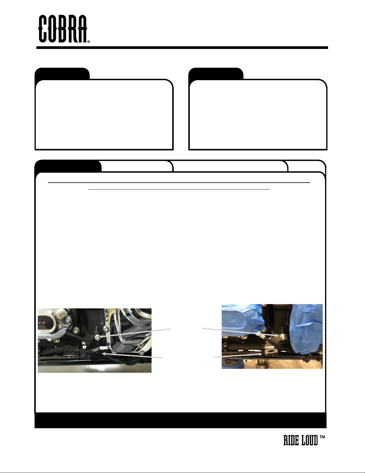
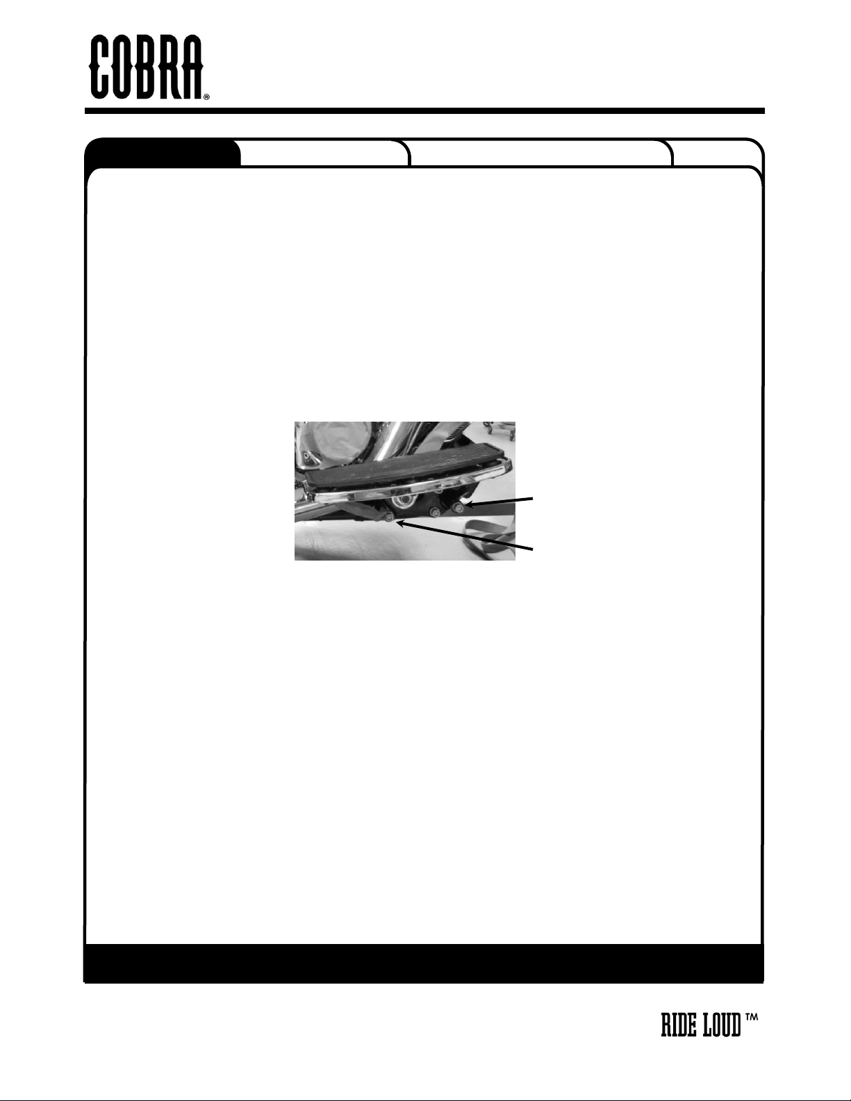
28. Insert the supplied floorboard spacer plate between the rear floorboard mount and the frame, then align
the dowel pin and reinstall the socket head bolt. Tighten to factory specifications. See FIGURE 13.
29. Remove the socket head bolt from the right front floorboard mount. Place the supplied thick washer
between the front floorboard mount and the frame. Reinstall and tighten the socket head bolt to factory
specifications. See FIGURE 13.
30. Reinstall any other previously removed items. Tighten to factory specifications.
31. Make sure all the hardware (brackets, headpipes, heatshields, mufflers and floorboards) have been
tightened appropriately.
32. IMPORTANT: On BLACK exhaust, before starting your engine remove all fingerprints from all
exhaust surfaces. To clean your black exhaust system, use a liquid based soap detergent, such as
dishwashing soap applied with a soft cloth and rinse with clean water. Note: Avoid abrasive
cleaning methods such as granular or dry cleansers, simple green, scotch-brite or steel wool
pads. Abrasives may breach the coating and shorten life.