Cobra Ride Loud User manual

23801 E. La Palma Ave., Yorba Linda, CA 92887 Ph. 714.692.8180 Fax. 714.692.5016
www.cobrausa-vtwin.com
09/21
1
PRIOR TO INSTALLATION, MAKE SURE YOUR STOCK HEADPIPE GASKETS ARE IN GOOD CONDITION.
IF YOU HAVE ANY DOUBTS AS TO THEIR CONDITION, REPLACE THEM.
Read all instructions carefully and completely before installing your new exhaust system!
1. Remove the saddle bags, right side cover, and right front floorboard from the frame.
2. Unplug the O2 sensors on the front and rear headpipes from the motorcycle wire harness.
3. Remove the stock exhaust system being careful not to damage the headpipe gaskets. If the headpipe
gaskets are in good condition they do not need to be removed from the cylinders. Remove and save the
flanges, nuts, retaining rings, muffler clamps, muffler mount bolts, crossover bracket bolts, and O2 sensors
from the stock exhaust. Label the O2sensors front and rear to ensure they will be installed on the proper
headpipe.
4. Remove the stock exhaust mount bracket.
5. Install the supplied headpipe support bracket using the stock nut. On 2017-2020 models route the hydraulic
clutch line behind the bracket. On 2021 models route the clutch cable in front of the bracket. See
FIGURES 1 & 2. Lightly snug the nut but DO NOT TIGHTEN so the bracket can be adjusted. The bracket
should be positioned at a slight angle.
Items Supplied >
1 –FRONT HEADPIPE AND HEATSHIELD
1 –REAR HEADPIPE COLLECTOR ASSEMBLY AND HEATSHIELD
1 –LEFT REAR CROSSOVER PIPE AND HEATSHIELD
1 - RIGHT MUFFLER 2 –FISHTAIL TIPS
1 - LEFT MUFFLER 4 –1/4-20 X 3/8 BUTTONHEAD BOLTS
1 –BRACKET, FRONT HEADPIPE SUPPORT
1 –BRACKET, CROSSOVER WITH GROMMET PIPE SUPPORT
1 –FLOORBOARD MOUNT SPACER PLATE
1 –CLAMP, FRONT HEADPIPE SUPPORT
8 –CLAMP, HOSE HS-24 2–FISHTAIL TIPS
2 –CLAMP, HOSE HS-28 1 –3/8” NYLOCK NUT
1 –THICK 3/8” WASHER 2 - 1/4 SHOULDER BOLTS
1 –3/8” X 1” CARRIAGE BOLT 4 –CLAMP, 27-61 MSC
1 –THIN 3/8” WASHER, 2 - 1/4 & 2 - 5/16 LARGE FLAT WASHERS
Application(s) >
HARLEY:
DRESSER ’17 - ‘21
Instruction Manual >
6975
Page 1 of 6
DOCUMENT NO. 0017 REV. A
Continued on Page 2
DISCLAIMER: NOT LEGAL FOR SALE OR USE IN CALIFORNIA ON ANY POLLUTION CONTROLLED MOTOR VEHICLE. THE SALE, USE, OR
INSTALLATION OF THIS PRODUCT MAY ALSO BE ILLEGAL NATIONWIDE UNDER THE FEDERAL CLEAN AIR ACT (42 U.S.C.§ 7522(A)(3)).
FIGURE 1
2017 –2020
MODELS
STOCK NUT
COBRA HEADPIPE
SUPPORT BRACKET
FIGURE 2
2017 –2020
MODELS

23801 E. La Palma Ave., Yorba Linda, CA 92887 Ph. 714.692.8180 Fax. 714.692.5016
www.cobrausa-vtwin.com
09/21
2
Instruction Manual >
6975
Page 2 of 6
6. Install the stock flanges, retaining rings and O2 sensors onto the supplied front and rear headpipes. Be sure
to install the front O2sensor on the front headpipe and the rear O2sensor on the rear headpipe.
7. Install the front headpipe (with stock gasket in place) onto the front cylinder using the stock nuts. Snug the
nuts but DO NOT TIGHTEN at this time.
8. Slide the supplied pinch clamp over the front headpipe making sure the square hole on the clamp is facing
up and towards the inside. Position the clamp over the support bracket so that the pinch clamp captures
both sides of the bracket. See FIGURE 3. Insert the supplied 3/8” carriage bolt through the top of the pinch
clamp and support bracket. Install the 3/8” thin flat washer and nut onto the bottom of the carriage bolt but
DO NOT TIGHTEN at this time. Leave the nut loose so the headpipe can be adjusted.
9. Position (2) of the supplied #27-61 MSC muffler clamps onto the rear headpipe collector assembly inlet and
outlet. The hex head of both clamps should be inward and down. See FIGURE 4. (NOTE: The clamps
should be flush with the end of the inlet and outlet when tightened. See FIGURE 4. If the clamps are slid
past the slots on the inlet and outlet the clamps will not tighten properly).
10. Install the rear headpipe collector assembly (with stock gasket in place) onto the rear cylinder and on
to the front headpipe. Make sure the front headpipe is pushed in as far as possible into the rear
headpipe collector assembly inlet. Use the stock nuts to fasten the headpipe to the cylinder. Snug the
nuts but DO NOT TIGHTEN at this time. See FIGURE 5.
11. Install the left rear crossover pipe onto the rear headpipe collector assembly making sure it slides into the
outlet of the rear headpipe collector assembly outlet as far as possible. See FIGURE 5.
DOCUMENT NO. 0018 REV. A
Continued on Page 3
FIGURE 3
FRONT HEAD PIPE
SUPPORT BRACKET
CARRIAGE BOLT
PINCH CLAMP
3/8” THIN FLAT
WASHER AND NUT
POSITION 27-61MSC
CLAMP WITH HEX
HEAD FACING IN
AND DOWN
CLAMPS SHOULD BE
FLUSH WITH EDGE OF
COLLECTOR
DO NOT SLIDE CLAMPS
PAST SLOTS
FIGURE 4
CLAMPS SHOULD BE
FLUSH WITH EDGE OF
COLLECTOR
(INWARD SIDE OF COLLECTOR)

23801 E. La Palma Ave., Yorba Linda, CA 92887 Ph. 714.692.8180 Fax. 714.692.5016
www.cobrausa-vtwin.com
09/21
3
Instruction Manual >
6975
Page 3 of 6
12. Using FIGURE 6 below, insert the 5/16” I.D. washer over both supplied shoulder bolts, make sure the
smooth side of the washer is facing toward the threads of the bolts. Insert them through the grommets on
the supplied bracket, be sure the bracket is oriented as shown in FIGURE 6. On the other side of the
bracket, install the ¼” I.D. washer over the shoulder bolt threads. Ensure that the smooth side of each
washer is contacting the grommet. (The stamped side with sharp edge must face away from the grommet
to ensure long life of the grommet.) Apply blue Loctite to the threads of the shoulder bolts. Thread both
shoulder bolts and bracket assembly loosely onto the welded mount on the crossover assembly. See
FIGURE 6.
13. Apply blue Loctite on the (2) stock allen bolts, install them along with (2) stock washers into the mount
bracket upper holes and transmission, lightly snug the bolts but DO NOT TIGHTEN at this time, see
Figure 7. Adjust the crossover pipe fore and aft so the mount with grommets rest flush against the rear of
the transmission case. IMPORTANT: DO NOT force the crossover pipe forward or backward or up and
down to get it into position. If a lot of force is needed to align the crossover pipe and support bracket then
adjust the rear headpipe collector assembly until it will align with only enough force to counter act the
weight of the left side of the crossover assembly. Also, make sure the crossover pipe has clearance all
around and does not make contact with the transmission pan. Adjust as needed while bolts are loose.
DOCUMENT NO. 0018 REV. A
Continued on Page 4
NOTE: Arrows point to
the position of the hex
head of the clamps.
FIGURE 5
27-61 MSC
CLAMP
FRONT HEADPIPE
SUPPORT
REAR
CROSSOVER PIPE
FIGURE 6

23801 E. La Palma Ave., Yorba Linda, CA 92887 Ph. 714.692.8180 Fax. 714.692.5016
www.cobrausa-vtwin.com
09/21
4
Instruction Manual >
6975
Page 4 of 6
14. Slide the supplied clamps over the inlets of the right and left mufflers. Position them as shown in FIGURE 8 with
the hex head facing inward and towards the ground.
15. Install the mufflers onto the crossover pipe assembly and insert the (2) stock 5/16-inch bolts into each rear
muffler mount the same as stock. Do not tighten clamps or bolts at this time.
16. Make sure the front headpipe, rear headpipe collector assembly, left rear crossover pipe, and mufflers are
aligned properly and tighten the (2) crossover support bracket shoulder bolts, then proceed to tighten the
(2) previously installed stock allen bolts in the transmission case to factory specification. See FIGURE 7.
17. Fully tighten the flange nuts on the exhaust port studs, followed by the nut for the 3/8” carriage bolt on the
front headpipe support clamp and the nut on the front headpipe support bracket. See FIGURES 1, 2 & 3.
18. Next fully tighten the (2) 27-61MSC clamps on the rear headpipe collector assembly. (NOTE: The clamps
should be flush with the end of the crossover assembly inlets when tightened. See FIGURES 4 & 5. If the
clamps are slid past the slots on the crossover assembly inlet the clamps will not tighten properly).
19. From the rear, rotate the mufflers as needed so they are level with the ground and parallel with each other.
Then tighten the clamps and the mount bolts. (NOTE: The clamps should be flush with the end of the
muffler inlets when tightened. See FIGURE 8. If the clamps are slid past the slots on the slip inlet the
clamps will not tighten properly).
20. Plug the O2sensors back into the motorcycle wire harness and route the wires away from the exhaust in
the same manner as stock.
21. Remove the heatshields and hose clamps from packaging. Unscrew the hose clamps and feed the tail end
of the clamps through the clips on the inside of the heatshield so the screws are accessible with a
screwdriver once the heatshield is installed. The larger HS-28 clamps go to the rear of the heatshield
where they will rest on the muffler body. The smaller HS-24 clamps go on the front of the heatshields
where they will rest on the headpipes. See FIGURE 9 & 11 for proper positioning of the clamps on the
heatshields. (NOTE: The arrows point to the positioning of the hex head of the clamps. The hex head
of the clamps should be accessible for tightening but not visible when the heatshields are mounted to the
pipes.)
DOCUMENT NO. 0018 REV. A
Instruction Manual
>
STOCK
BOLTS
CROSSOVER
PIPE
COBRA CROSSOVER
SUPPORT BRACKET
WITH GROMMETS
SUPPLIED SHOULDER
BOLTS AND WASHERS
FIGURE 7
LEFT MUFFLER
POSITION 27-61 MSC
CLAMP WITH HEX HEAD
FACING DOWN AND IN
FIGURE 8
RIGHT MUFFLER
CLAMP SHOULD BE
FLUSH WITH EDGE
OF INLET
Continued on Page 5

23801 E. La Palma Ave., Yorba Linda, CA 92887 Ph. 714.692.8180 Fax. 714.692.5016
www.cobrausa-vtwin.com
09/21
5
6975
Page 5 of 6
22. Install the right rear heatshield over the rear headpipe by first sliding the rear portion of the heatshield over
the muffler. Continue to slide the heatshield forward while pushing the front of the heatshield gently
between the motor and frame. (Hint: Spread the hose clamps apart slightly to make it easier to slide them
over the headpipes.) Align the heatshield with the headpipe and the collector heatshield. There should be
an even gap around the collector heatshield. Snug the clamps but DO NOT TIGHTEN at this time. See
FIGURE 9 & 10.
Instruction Manual >
Continued on Page 6
HS-28
CLAMP
FIGURE 11
HS-24
CLAMP
NOTE: Arrows point to
the position of the hex
head of the clamps.
DOCUMENT NO. 0018 REV. A
Instruction Manual
>
FIGURE 10
10-24 BUTTONHEAD
BOLT
10-24 BUTTONHEAD
BOLT
COLLECTOR
HEATSHIELD
FIGURE 9
HS-24
CLAMP
HS-24
CLAMP
HS-28
CLAMP
NOTE: Arrows point to
the position of the hex
head of the clamps.
HS-24
CLAMP
HS-24
CLAMP
HS-24
CLAMP
27-61
CLAMP

23801 E. La Palma Ave., Yorba Linda, CA 92887 Ph. 714.692.8180 Fax. 714.692.5016
www.cobrausa-vtwin.com
09/21
6
Instruction Manual >
6975
Page 6 of 6
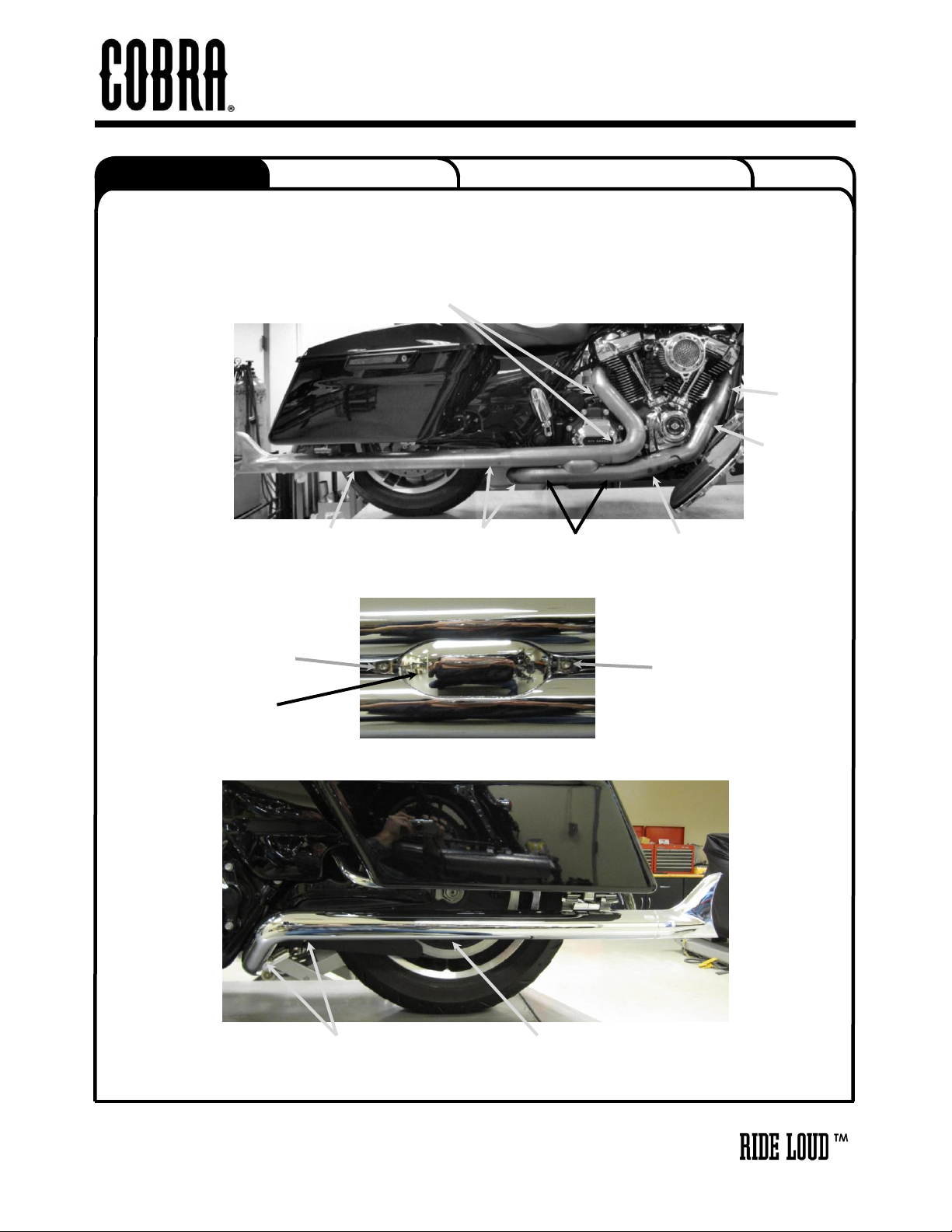
23. Install the right front heatshield over the right front headpipe. (Hint: Spread the hose clamps apart slightly to
make it easier to slide them over the headpipes.) Align the heatshield with the headpipe and the collector
heatshield. There should be an even gap around the collector heatshield. If the heatshield does not align
well with the collector heatshield then the rear crossover pipe may need to be loosened and pushed
forward or backward. When the heatshield is aligned properly snug the clamps but DO NOT TIGHTEN at
this time. See FIGURE 9 & 10.
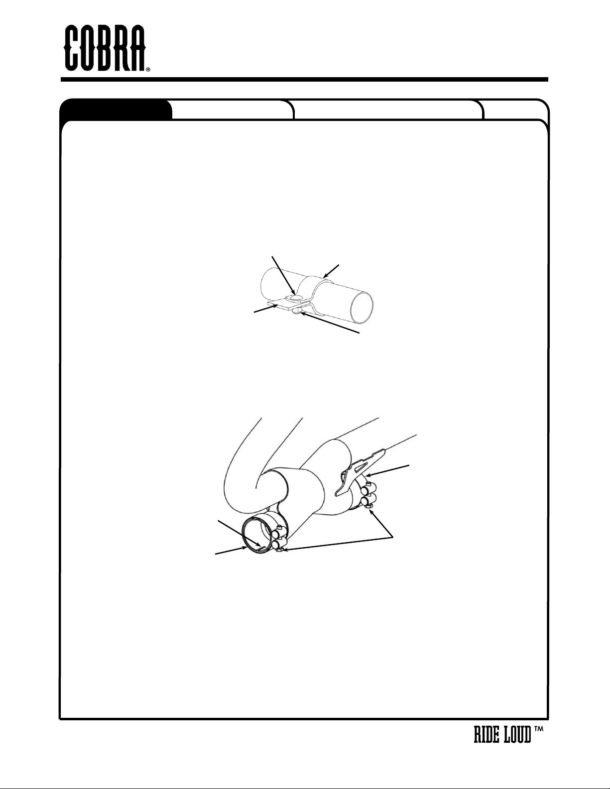
24. If the heatshields will not align properly with the collector heatshield then the collector heatshield may need
to be loosened and moved forward or backward. Loosen the two button head bolts to adjust the collector
heatshield forward or backward. See FIGURE 10.
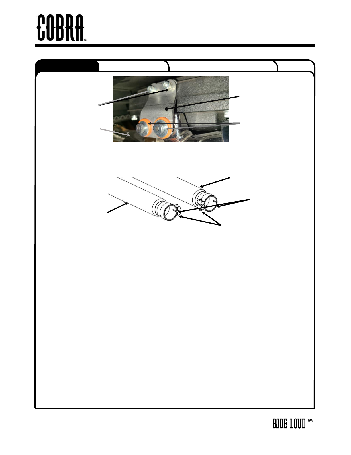
25. Install the left rear heatshield over the left rear muffler and crossover headpipe by first sliding the rear
portion of the heatshield over the muffler. Continue to slide the heatshield forward while pushing the front of
the heatshield gently into position. (Hint: Spread the hose clamps apart slightly to make it easier to slide
them over the headpipes.) Make sure the muffler clamp does not interfere with the heatshield and are
aligned as shown in FIGURE 11. Align the heatshield with the muffler and crossover headpipe and snug
the clamps but DO NOT TIGHTEN at this time.
26. Align the threaded holes in the side of the fishtail tip with the holes in the muffler heatshield and slide it into
the rear of the heatshield and muffler. (NOTE: If it is difficult to slide the tip into the heatshield loosen the
clamps on the muffler heatshield. Failure to do this may cause damage to the tips.) Fasten the tip with (2)
of the supplied ¼-20 button head screws making sure there is no gap between the tip and muffler
heatshield when tightened. Do this for both left and right sides.
27. Make sure the rear of both fishtail tips are even on the back with each other.
28. Once the tips and heatshields are aligned properly tighten all hose clamps securing the heatshields.
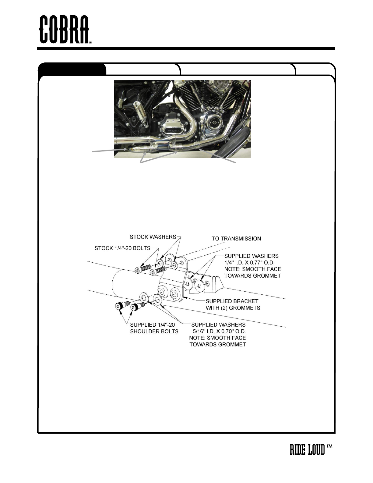
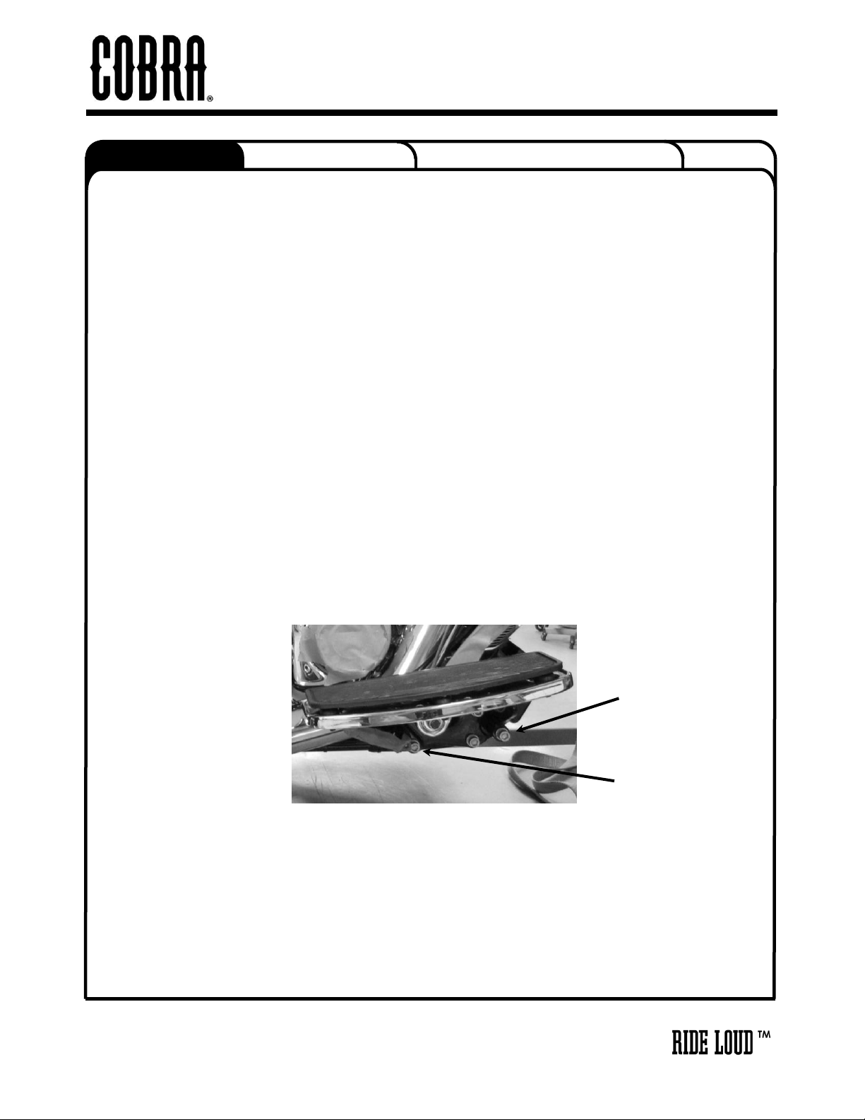
29. Insert the supplied floorboard spacer plate between the rear floorboard mount and the frame, then align the
dowel pin and reinstall the allen bolt. Tighten to factory specifications. See FIGURE 12.
30. Remove the allen bolt from the right front floorboard mount. Place the supplied thick washer between the
front floorboard mount and the frame. Reinstall and tighten the allen bolt to factory specifications. See
FIGURE 12.
28. Reinstall any other previously removed items. Tighten to factory specifications.
29. Make sure all the hardware (brackets, headpipes, heatshields, mufflers and floorboards) have been
tightened appropriately. Recheck after first 500 miles and again at each oil change.
30. IMPORTANT: Before starting your engine remove all fingerprints from chrome with a quality wax or
chrome polish. Failure to do so can cause chrome discoloration. Due to fluctuations in fuel delivery
settings, timing, etc., Cobra Engineering does not warrant against chrome discoloration.
DOCUMENT NO. 0018 REV. A
Instruction Manual
>
FIGURE 12
INSTALL SPACER
PLATE ON REAR
MOUNT
INSTALL THICK 3/8”
FLAT WASHER ON
FRONT MOUNT
This manual suits for next models
1
Table of contents
Other Cobra Motorcycle Accessories manuals

Cobra
Cobra 601-2108 User manual

Cobra
Cobra 602-2000 User manual

Cobra
Cobra 4918 User manual

Cobra
Cobra 05-9349 User manual

Cobra
Cobra 6468B User manual

Cobra
Cobra Fi2000 User manual

Cobra
Cobra 602-2610B User manual

Cobra
Cobra 602-1103B User manual

Cobra
Cobra 06-0225-01B User manual

Cobra
Cobra 602-2615 User manual

Cobra
Cobra FLHC 2018 User manual

Cobra
Cobra 06-0225-02B User manual

Cobra
Cobra Fi2000 PowrPro User manual

Cobra
Cobra 602-2500 User manual

Cobra
Cobra 602-2601 User manual

Cobra
Cobra Fi2000 User manual

Cobra
Cobra 02-4265 User manual

Cobra
Cobra 6255RB User manual

Cobra
Cobra 602-2005 User manual

Cobra
Cobra 602-2006 User manual