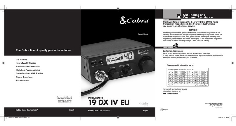
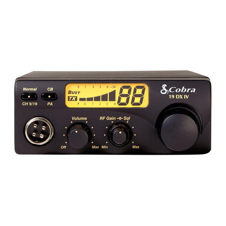
Cobra 19 DX III User manual

1
Contents
Features. . . . . . . . . . . . . . . . . . . . . . . . . . . . . . . . . . . . . . . . 1
The CB Story . . . . . . . . . . . . . . . . . . . . . . . . . . . . . . . . . . A1
Licensing/Warning/Included Accessories. . . . . . . A1
Controls and Indicators . . . . . . . . . . . . . . . . . . . . . . . A2
OurThanks to You. . . . . . . . . . . . . . . . . . . . . . . . . . . . . A3
Customer Support . . . . . . . . . . . . . . . . . . . . . . . . . . A3
Operating Your CB Mobile Radio
Installation/Connection. . . . . . . . . . . . . . . . . . . . . . . . . . 2
Turning On. . . . . . . . . . . . . . . . . . . . . . . . . . . . . . . . . . . . . .4
CB Antenna . . . . . . . . . . . . . . . . . . . . . . . . . . . . . . . . . . . . . 4
Microphone Connector . . . . . . . . . . . . . . . . . . . . . . . . . . 5
Squelch. . . . . . . . . . . . . . . . . . . . . . . . . . . . . . . . . . . . . . . . .5
Setting Squelch . . . . . . . . . . . . . . . . . . . . . . . . . . . . . . . . . 6
Channel Selection . . . . . . . . . . . . . . . . . . . . . . . . . . . . . . . 8
Channel 9/NOR. . . . . . . . . . . . . . . . . . . . . . . . . . . . . . . . . . 8
CB/PA. . . . . . . . . . . . . . . . . . . . . . . . . . . . . . . . . . . . . . . . . . . 8
S/RF Power Meter. . . . . . . . . . . . . . . . . . . . . . . . . . . . . . . . 9
TX Indicator LED. . . . . . . . . . . . . . . . . . . . . . . . . . . . . . . . . 9
Antenna Connector. . . . . . . . . . . . . . . . . . . . . . . . . . . . . 10
External Speaker . . . . . . . . . . . . . . . . . . . . . . . . . . . . . . . 10
Power . . . . . . . . . . . . . . . . . . . . . . . . . . . . . . . . . . . . . . . . . 10
Public Address . . . . . . . . . . . . . . . . . . . . . . . . . . . . . . . . . 10
Ignition Noise Interference. . . . . . . . . . . . . . . . . . . . . . 11
Temporary Mobile Operation. . . . . . . . . . . . . . . . . . . . 11
Operation to Receive/Transmit . . . . . . . . . . . . . . . . . . 12
Maintenance. . . . . . . . . . . . . . . . . . . . . . . . . . . . . . . . . . . 13
Frequency Ranges. . . . . . . . . . . . . . . . . . . . . . . . . . . . . . 15
Specifications . . . . . . . . . . . . . . . . . . . . . . . . . . . . . . . . . 16
Accessories . . . . . . . . . . . . . . . . . . . . . . . . . . . . . . . . . . . . 17
Order Form . . . . . . . . . . . . . . . . . . . . . . . . . . . . . . . . . . . . 19
Warranty. . . . . . . . . . . . . . . . . . . . . . . . . . . . . . . . . . . . . . 20
If You Think You Need Service . . . . . . . . . Back Cover
Featuresof ThisProduct
• 40CBRadio Channels
• InstantChannel9/NOR
• PASystem
• CompactSize
• DynamicMicrophone
• 9FootMicCord
• FrontPanelMicrophone
Connector
How to Use Your
Cobra 19DXIII
19 DX III. LAYOUT(4478) 8/9/00 4:35 PM Page 1

4Connect the red lead of DC power cord to an
accessory 12 volt fuse.
5Connect the black leadto the negative side of
theautomobile.This is usually the chassis.Any
convenientlocation with good electricalcontact
(removepaint) may be used.
6Mount the microphone bracket on right side of
thetransceiveror near it using two screws sup-
plied.Whenmountinginanautomobile,place
thebracket under the dash so the microphone
is readily accessible.
7Attach the 4-pin microphone cable to recepta-
cle on front of unit and install unit in bracket
securely.
Mounting andConnections
Select a locationfor the transceiver and micro-
phonebracketthat is convenientforoperation.
Inautomobiles,thetransceiveris usually mounted
totheunderneathof the dash panel,with the
microphone bracket besideit.
1Hold theradio with mountingbracket in the
exactlocationdesired.Remove the mounting
bracket and use it as atemplateto mark the
locationforthe mounting screws.
2Drill necessary holes and securemounting
bracket in location.
3Connect theantennacable plug tothe recepta-
clemarked“ANT”on the backof the unit.
3
Mounting and
Connections
Note
BeforeinstallingtheCB radio,
visuallycheckthevehicle bat-
teryconnectionstodetermine
whichbatteryterminal, posi-
tiveornegative(positive is the
largerofthetwo)isgrounded
totheengineblock
(orchassis).
Operation
2
Mounting and
Connections
Note
Thetransceiverisheld in the
universalmountingbracketby
two thumbscrews,permitting
adjustmentatthemost conve-
nientangle.
Auniversalmountingbracket
issuppliedalongwith self tap-
pingscrewsandstarwashers.
Tomountthetransceiver:
OperationInstallation Installation
CB Transceiver
19 DX III. LAYOUT(4478) 8/9/00 4:35 PM Page 2

5
MicrophoneConnector
Allows for convenientremoval of the microphone
plug when storageisrequired.Themicrophone
MUSTbeconnectedto the unitat all times when in
use,for properoperation.
Squelch
This controlis used to cut off or eliminate receiver
background noisein theabsence of an incoming
signal. Adjust until the receiver noise disappears.
This will require theincomingsignal to be slightly
stronger than average receivernoise.Further clock-
wise rotation will increase the threshold level
which a signal must overcome inorder to be heard.
Only strong signals will beheard at a maximum
clockwise setting.
Microphone
Connector
Operation
4
Turning on
Turn volume control clockwise to turn poweron
and set the desired listening volume.
CB Antenna
Onlya properly matched antenna systemwill
allow maximum poweroutput.
Inmobileinstallations(cars,trucks,boats,etc.),
anantennasystemthatis non-directional should
be used.
When installed in a boat,thetransceiver willnot
operate at maximum efficiency without a ground
plate unless the vessel has asteel hull.Before
installingthe transceiver in a boat,consult your
dealerforinformation regarding an adequate
groundingsystem.
Turning on
Your Radio
Operation
CB Antenna
Note
Cobraloaded-typeantenna
modelsHGA1000,HGA1500,
andHGA2000arehighlyrec-
ommendedformostinstalla-
tions. ConsultyourCobradeal-
erforfurtherdetails(orsee
orderform atthebackof
thisbook).
3-WayCombinationAntennas
areavailablewhichallowoper-
ationof all threebands (AM-FM
&CB),usingasingleantenna.
However,useofthistypeof
antennausuallyresultsinless
thannormaltransmitand
receiverangewhencompared
toastandard-type"Single
Band" antennadesignedfor
CBonly.
Squelch
19 DX III. LAYOUT(4478) 8/9/00 4:35 PM Page 4

7
3. To achieve the DesiredSquelch Setting(DSS),
turnthe Squelchcontrolcounterclockwiseuntil
you hear noise. Now turn the control clockwise
just untilthe noise stops. This is the DSS setting.
Operation
6
Operation
Gateopen
Gateset toDesired
Squelch Setting(DSS)
Gateclosed
Setting
Squelch
Setting Squelch
Squelch is the “control gate”for incoming signals.
1. Fullclockwise rotation closes the gate
allowing only very strong signals to enter.
2. Fullcounterclockwise rotation opens the“gate”
allowing all signals in.
19 DX III. LAYOUT(4478) 8/9/00 4:35 PM Page 6

9
S/RFPower Meter
Showsrelative transmitter RFoutput power and
inputsignalstrengthwhenreceiving.TheLED(Light
EmittingDiode) segments glow green to amber to
red...thisindicates receiveor transmitactivity.
TX Indicator LED
Theindicatorwilllightredwheninthetransmitmode.
S/RF
PowerMeter
Operation
TX Indicator
LED
Channel
Selection
8
Selectinga Channel
Rotatechannel knobclockwise untildesired chan-
nelis displayed.
Channel 9/NOR
SetCH9toobtaininstantaccessemergencychan-
nel.In NOR position,all 40CB channelsare selected
by the channel button.
CB/PA
IntheCBposition,thePAfunctionisdisabledandthe
unitwilltransmitandreceiveontheselectedchannel.
ThePAfunctionshouldnotbeusedunlessaPAspeaker
isconnected.
Operation
Channel 9/
NOR
CB/PA
19 DX III. LAYOUT(4478) 8/9/00 4:35 PM Page 8

11
Ignition NoiseInterference
Use of a mobile receiver atlow signal levels is nor-
mally limitedby the presence ofelectrical noise.
Under mostoperatingconditions,when signal
levelis adequate,the background noisedoes not
present a serious problem.Also,when extremely
low level signals are being received,the transceiver
may be operated withvehicle engine turned off.
Theunitrequires very little current andtherefore
will notsignificantly discharge the vehiclebattery.
Even though this radio hasan automaticnoise lim-
iter,in some installations ignition interference may
be high enough to make good communications
impossible.Consult your COBRA dealeror a 2-way
radio technician for helpin locating and correcting
the source of severe noise.
TemporaryMobileOperation
Fortemporarymobileoperation,you may wantto
purchase an additionalcigarettelighteradapter
from your COBRA dealer.This adapter and a mag-
netic mount antenna allow youto quickly "install"
your transceiverfor temporaryuse.
Operation
Ignition Noise
Interference
Temporary
Mobile
Operation
Note
Red wireis connectedtoposi-
tive side of socketcentertip.
Black wire is connectedto ne
g
ative sidecontacts.
Note
Radio resetstoCH 9 when con
nectedtocigarettelighterplug
Note
Whenusing theunit withcig-
aretteadapter,turnoffwhen
notin use toavoid draining
the battery.
10
RearPanel
Antenna Connector.This female connector per-
mits connection of the transmission line cable
male connector to the transceiver.
ExternalSpeaker.The External Speaker Jack is
used for an external speaker.The external speak-
er should have 8-ohm impedance and be rated
to handle at least 4.0 watts.When the external
speaker is plugged in,the internal speaker is
automatically disconnected.
Power: Thesewiressupply power to theCB radio.
This cable is permanently attachedto the radio.If
youwishto remove the radio afterinstallation,dis-
connect at fuse holderand ground connector.
Public Address: An external PA speaker may be
connected to the PA speaker jack when used as a
public address system.The speaker should be
directed away from the microphone to prevent
acoustic feed-back.Physical separation or isola-
tion of the microphone and speaker must be
employed when operating the PA at high
output levels.
Antenna
Connector
Operation
External
Speaker
Power
Note
Cobra external speakersare
rated 15 watts
19 DX III. LAYOUT(4478) 8/9/00 4:35 PM Page 10

13
Maintenance/
Adjustment
Maintenance
Maintenance and Adjustment
Your COBRA CB transceiver is specifically
designed for the environment encountered in
mobile installations.The use of all solid state cir-
cuitry and its light weight result in high reliabili-
ty.Should a failure occur,however, review the fol-
lowing,then if necessary,replace parts only with
identical parts. Do not substitute.
1. Check connections to the source of power and
make sure it is the 13.8 VDC required to oper-
ate your radio.
2. Check the fuses in the DC power cord.The
main power lead (red ) has a 2 amp 3AG type
fuse in its holder.Use only the above specified
type and size fuse for maximum protection.
Failure to do so will void the warranty.
3. Make certainthe microphone is properly
pluggedin.
4. Make certain the antenna is properly assem-
bled and connected.
If you are unable to correct the problem, refer to
the SERVICE INSTRUCTIONS at the end of this
manual for the correct procedure for warranty
and post-warranty service from COBRA.
12
Operating Procedure to Receive
1. Be sure that power cord,antenna and microphone are connected to the
proper connectors before proceeding further.The CB/PA switch should
be in the "CB" position.
2. Turn the radio ON by rotating the VOLUME CONTROL clockwise.
3. Rotate SQUELCH CONTROL counterclockwise until incoming signal is
heard.
4. Select the desired channel.
5. SetVOLUME CONTROL to a comfortable listening level.
Operating Procedure to Transmit
1. Select the desired channel.
2. The receiver and transmitter are controlled by the press-to-talk switch on
the microphone.Press the switch and the transmitter is activated;release
switch to receive.When transmitting (on a clear channel),hold the micro-
phone two inches from the mouth and speak clearly in a normal voice.
Be sure the antenna is properly connected to the radio before transmit-
ting.Prolonged transmitting without an antenna,or a poorly matched
antenna,could cause damage to the transmitter.
Operation
19 DX III. LAYOUT(4478) 8/9/00 4:35 PM Page 12

15
Frequency Range
s
The Cobra19DXIIItransceiverrepresents one ofthe
mostadvancedAMtwo-wayradiosusedasa ClassD
station inthe CitizensRadio Service.Thisunitfeatures
advanced Phase Lock Loop(PLL) circuitryproviding
completecoverage ofall40 CBchannels.
1 26.965 21 27.215
2 26.975 22 27.225
3 26.985 23 27.255
4 27.005 24 27.235
5 27.015 25 27.245
6 27.025 26 27.265
7 27.035 27 27.275
8 27.055 28 27.285
9 27.065 29 27.295
10 27.075 30 27.305
11 27.085 31 27.315
12 27.105 32 27.325
13 27.115 33 27.335
14 27.125 34 27.345
15 27.135 35 27.355
16 27.155 36 27.365
17 27.165 37 27.375
18 27.175 38 27.385
19 27.185 39 27.395
20 27.205 40 27.405
Channel Channel
CB Freq. CB Freq.
Channel In MHz Channel In MHz
Permitted:"A tornado sighted six miles of town."
Not Permitted :"This is observation post number 10.
No tornado sighted."
Warning
14
Channel 9
Emergency
Messages
ReplacementWarning
Replacement or substitution of certain parts with
replacements other than those recommended by
Cobra may be a violation of the technical regula-
tions of Part 95 of the FCC rules,or of Type
Acceptance requirements of Part 2 of said rules.
When making adjustments,be sure tore-read
applicable portions of this instruction manual to
make certainyouarefollowingcorrect procedure
and that the radio was properly installed,etc.
A Few Rules That Should Be Obeyed
1. You are not allowed to carry on a conversation with
another station for more than five minutes at a time with-
out taking a one-minute break to give others a chance to
use the channel.
2. You are not allowed to blast others off the air by overpow-
ering them with illegally amplified transmitter power or
illegally high antennas.
3. You can't use CB to promote illegal activities.
4. You are not allowed to use profanity.
5. You may not play music in your CB.
6. You may not use your CB to sell merchandise or profes-
sional service.
Use Channel 9 For Emergency Messages Only
The FCC gives the following examples of permit-
ted and prohibited types of communications for
use on Channel 9.These are guidelines and are
not intended to be all-inclusive.
A Few Rules
You Should
Know
19 DX III. LAYOUT(4478) 8/9/00 4:35 PM Page 14

17
Accessories
16
Specifications
Specifications
GENERAL
CHANNELS. . . . . . . . . . . . . . . . . . . . . . . CB - 40 CH
FREQUENCY RANGE. . . . . . . . . . . . . . . CB - 26.965TO 27.405 MHZ
FREQUENCYTOLERANCE. . . . . . . . . . 0.005 %
FREQUENCY CONTROL . . . . . . . . . . . . PLL (PHASE LOCK LOOP) SYNTHESIZER
OPERATING TEMPERATURE
RANGE. . . . . . . . . . . . . . . . . . . . . . . . . . . -30° C TO + 65° C
MICROPHONE . . . . . . . . . . . . . . . . . . . . PLUG-IN DYNAMIC
INPUTVOLTAGE . . . . . . . . . . . . . . . . . . 13.8VDC nom.(negative ground)
CURRENT DRAIN TRANSMIT: AM FULL MOD.,1.4A (MAXIMUM)
RECEIVE:SQUELCHED, 0.9 A;
FULL AUDIO OUTPUT,1.2A (NOMINAL)
SIZE . . . . . . . . . . . . . . . . . . . . . . . . . . . . .6-7/8”D X 6-3/4”W X 1-7/8”H
WEIGHT . . . . . . . . . . . . . . . . . . . . . . . . . .3.25 LBS.
ANTENNA CONNECTOR . . . . . . . . . . . .UHF;SO-239
METER . . . . . . . . . . . . . . . . . . . . . . . . . . .LED;INDICATES RELATIVE POWER
OUTPUT AND RECEIVED SIGNAL STRENGTH
TRANSMITTER
POWER OUTPUT . . . . . . . . . . . . . . . . . .4WATTS
MODULATION . . . . . . . . . . . . . . . . . . . .AM (AMPLITUDE MODULATION)
FREQUENCY RESPONSE . . . . . . . . . . . .300 TO 3000 HZ
OUTPUT IMPEDANCE . . . . . . . . . . . . . .50 OHMS,UNBALANCED
RECEIVER
SENSITIVITY . . . . . . . . . . . . . . . . . . . . . . .LESS THAN 1 µV FOR 10dB (S+N)
SELECTIVITY . . . . . . . . . . . . . . . . . . . . . .6 dB @ 7 KHZ,60 DB @ 10KHZ
IMAGE REJECTION . . . . . . . . . . . . . . . . .60 dB,TYPICAL
ADJACENT-CHANNEL REJECTION . . .50 dB,TYPICAL
ATOMATIC NOISE LIMITER . . . . . . . . . .BUILT-IN
ReplacementMounting
Bracket
251-199-9-001 $4.50
Replacement Thumb Screws
634-081-9-001
$0.60
Replacement Microphone
Bracket
741-080-9-001 $0.45
4PinPowerMicrophone
HGM75 $25.95
4PinNoiseCanceling
Microphone
HGM77 $30.95
4PinReplacementDynamic
Microphone
HGM73 $19.95
4PinPremiumNoise-
Cancelling Microphone
HGM84 $74.95
4PinPremium Noise-
CancellingMicrophone
WoodGrain
HGM84W $74.95
5PinPremiumNoise-
CancellingMicrophone
HGM85 $74.95
19 DX III. LAYOUT(4478) 8/9/00 4:36 PM Page 16

251-199-9-001 Replacement MountingBracket $4.50
634-081-9-001 ReplacementThumb Screws $0.60
741-080-9-001 Replacement Microphone Bracket $0.45
HG A1000 21”BaseLoadedMagneticMountAntenna $28.95
HG A1500 38”BaseLoadedMagneticMountAntenna $46.95
HG A2000 54”BaseLoadedMagneticMountAntenna $99.95
HG M84 4PinPremiumNoise-CancellingMicrophone $74.95
HG M84W 4PinPremiumNoise-CancellingMicWoodgr $74.95
HG M85 5PinPremiumNoise-CancellingMicrophone $74.95
HG M73
Replacement Dynamic Microphone
$19.95
HG M75 4 Pin Power Microphone $25.95
HG M77 Noise Canceling Microphone $30.95
HG S100 Dynamic External Speaker $21.95
HG S300 Noise Canceling External Speaker $28.95
HG S500 Noise Canceling
With Talk Back External Speaker $32.95
HG A300 FiberglassWhipReplacementAntenna $28.95
Black,Red,White,Gold
HG A400 FiberglassWhipReplacementAntenna $29.95
Black,Red,White,Gold
HG A450 FiberglassWhipReplacementAntenna $30.95
Black,Red,White,Gold
HG A6000 62”Center-LoadReplacement Antenna
Black/Clear,Black,Red,White,Gold $89.95
Tax Table
Illinois residents add 7%
Cook Co.residents add .75% (7.75% total)
Chicago residents add 1% (8.75% total)
Indiana residents add 5%
For credit card orders fill out order form
and fax to: 1.773.622.2269
or call 1.773.889.3087
(Press 1 from the main menu)
8:00 am - 6:00 pm,M-F,CST.
Make check or moneyorder (no stamps)
payable to:
Cobra Accessories Dept.
6500West Cortland St.Chicago,IL60707
Prices subject to change without notice.
Please print clearly
Name___________________________________________________
Address (No P.O.Box)_____________________________________
City____________________________________State____________
Zip_____________Telephone (____)__________________________
Credit Card No._________________________Exp.Date_________
Customer Signature__________________________________
Circle One: Visa MasterCard Discover
Subtotal
(Tax if applicable)
Shipping/handling
Total
Item # Description Cost Ea. Qty. Amou
Michigan residents add 4 %
Ohio residents add 6%
Wisconsin residents add 5%
Shipping& Handling
Amount of Shipping/
Order Handling
$25.00 and under $4.75 minimum
$25.01-$40.00 $6.95
$40.01-$80.00 $9.00
$80.01-$120.00 $10.00
$120.01-$160.00 $11.50
$160.01 and up $14.25
For AK,HI and PR please add
anadditional$15.00for UPS
shipments.
Accessory Order Form
19
38”BaseLoaded Magnet
MountAntenna
HGA1500 $46.95
54”Base Loaded Magnet
MountAntenna
HGA2000 $99.95
21”Base Loaded Magnet
MountAntenna
HGA1000 $28.95
Dynamic ExternalSpeaker
HGS100 $21.95 Noise Canceling External
Speaker
HGS300 $28.95
Noise Canceling With Talk
Back ExternalSpeaker
HGS500 $32.95
FiberglassWhip
ReplacementAntenna
3Foot HGA300 $28.95
Black,Red,White,Gold
4Foot HGA400 $29.95
Black,Red,White, Gold
41/2Foot HG A450 $30.95
Black,Red,White,Gold
62”Center-Load
ReplacementAntenna
HGA6000 $89.95
Black/Clear,Black,Red,White,Gold
Accessories
18
19 DX III. LAYOUT(4478) 8/9/00 4:36 PM Page 18
The Cobra line of quality products
also includes:
• High Gear™Accessories
• Radar Detectors
• SafetyAlert™
TrafficWarning Systems
• Family Radio Service (FRS)
2-Way Radios
Nothing comes close to a Cobra™
20
Limited Two Year Warranty
Limited Warranty
COBRA ELECTRONICS CORPORATION warrants that its
COBRA CB Transceiver,and the component parts thereof, will
be free of defects in material and workmanship for a period
of two (2) years from the date of consumer purchase.This
warranty may be enforced by the first consumer purchaser,
provided that the product is utilized within the U.S.A.
COBRA will,without charge, repair or replace,at its option, a
defective CB Transceiver upon delivery to the COBRA factory
Service Department,accompanied by proof of the date of
first consumer purchase,such a duplicated sales receipt.
You must pay initial shipping charges required to ship the
product for warranty service, but the return charges will be
at COBRA’S expense, if the product is repaired or replaced
under warranty.
Exclusions:This limited warranty does not apply; 1) to any
product damaged by accident;2) in the event of misuse or
abuse of the product or as a result of unauthorized alter-
ations or repairs;3) if the serial number has been altered,
defaced or removed;4) if the owner of the product resides
outside the U.S.A.
All impliedwarranties,including warranties ofmer-
chantability and fitness for a particular purpose are limited
in duration to the lengthof this warranty.
COBRA shallnot be liable for any incidental,consequential
or otherdamages; including, without limitation,damages
resulting from loss ofuseor cost ofinstallation.
Somestates donot allow limitations onhowlongan
impliedwarrantylasts and/or do notallow the exclusion or
limitationof incidental orconsequentialdamages,so the
above limitations maynot apply to you.
CobraElectronics
Corporation
6500WestCortlandStreet
Chicago,Illinois60707
19 DX III. LAYOUT(4478) 8/9/00 4:36 PM Page 20

Cobra Electronics Corporation
6500 West Cortland Street
Chicago, IL 60707
Cobra Electronics Corp.© 2000
Printed in China
Fortechnicalassistance,pleasecallourAutomated HelpDeskwhichcanassist
youbyansweringthemostfrequentlyaskedquestionsaboutCobraproducts.
(773)889-3087
24hours a day,7 days aweek.
A Consumer Service Representative can be reached through this same number
8:00 am - 6:00 pm,Monday through Friday,Central Standard Time.
Technicalassistance is alsoavailableon-lineinthe FrequentlyAskedQuestions (FAQ)
Ifyouthink you need servicecall1.773.889.3087
Ifyour productshould require factory service please call Cobra first before sending in your unit.
This will ensure the fastest turn-around time on your repair.
You may be asked to send your unit to the Cobra factory.It will be necessary to furnish the follow-
ing in order to have the product serviced and returned.
1. For Warranty Repair include some form of proof-of-purchase,such as a mechanical reproduction
or carbon of a sales receipt. If you send the original receipt it cannot be returned.
2. Send the entire product.
3. Enclose a description of what is happening with the unit.Include a typed or clearly print name
and address of where the unit is to be returned.
4. Pack unit securely to prevent damage in transit. If possible, use the original packing material.
5. Ship prepaid and insured by way of a traceable carrier such as United Parcel Service (UPS) or First
Class Mail to avoid loss in transit to: Cobra Factory Service,Cobra Electronics Corporation,6500
W. Cortland St., Chicago,IL 60707.
6. If the unit is in warranty, upon receipt of your unit it will either be repaired or exchanged
depending on the model. Please allow approximately 3 to 4 weeks before contacting us for
status.If the unit is out of warranty a letter will automatically be sent informing you of the
repair charge or replacement charge.If you have any questions, please call 1.773.889.3087
for assistance.
If You ThinkYou Need Service
“IngeniousProductsforEasierCommunication.”
19 DX III
Mobile Radio
Operating Instructions for your
19DXIII
Part No. 480-316-P-001
19 DX III. LAYOUT(4478) 8/9/00 4:36 PM Page 26

A1
The Citizens Band Story
4
5
21
3
TheCitizens Band lies between theshortwave broadcast
and 10-meter Amateurradio bands,and was established
bylaw in 1949. The Class D two-waycommunications
servicewas opened in1959.(CB alsoincludesa Class A
citizens band and ClassC remotecontrol frequencies.)
FCCRegulations
FCCregulationspermitonly "transmissions" (one-party
to another) rather than" broadcast" (to awide audience).
Thus,advertising is notallowed on CBchannels because
thatis"broadcasting".
FCCWarnings
All transmitteradjustments other than thosesupplied
bythemanufacturerasfrontpanel operatingcontrols,
mustbemade by,or underthe supervision of,theholder
ofan FCC-issuedgeneralRadio-Telephone Operator’s
License.
Replacement orsubstitution of transistors,regular di-
odes or other parts of aunique nature,withparts other
than thoserecommended by Cobra,maycauseviolation
ofthetechnicalregulationsof Part 95of the FCCRules,
or violation ofTypeAcceptancerequirements of Part 2
ofthe Rules.
You shouldreadandunderstand Part 95(includedwith
thisunit)of theFCCRulesand Regulations,before oper-
ating your Cobraradio,eventhoughtheFCCnolonger
requires youto obtain an operator’s license.
What’s included with yourCBRadio:
1. CB transceiver 6. FCC rules
2. Microphone .(notpictured)
3. Transceiverbracket 1.
4. Microphonebracket
5. Operating Manual
19 DX III. LAYOUT(4478) 8/9/00 4:36 PM Page 28

A2
Controls and Indicators
Thank you for purchasing the Cobra 19 DX III CB
Radio Transceiver. Properly used, this Cobra prod-
uct will giveyou many years of reliable service.
Customer Support
Should you encounter any problems with this
product, or not understand its many features,
please refer to this owner’s manual.If, after refer-
ring to the manual, you still need help,call Cobra
Customer Service at 773.889.3087.
CobraCustomer Service
Liveoperatorsare
available
M-F8:00am–6:00pm
CentralStandardTimeat
773.889.3087
AutomatedTechnical
Assistanceavailable24
hoursaday,sevendays a
week.E-mail questions to:
productinfo@
cobraelectronics.com
Cobraonthe WorldWide
Web:FrequentlyAsked
Questions(FAQ)canbe
foundat:
www.cobraelectronics.com
A3
1
7 6
Our Thanks to You
5
10
1. MicrophoneConnector.
2. Off/On/Volume.
3. Squelch.
4. Channel9/NOR
5. CB/PA
6. ChannelSelectorButton.
7. LEDChannelDisplay.
8. S/RFPowerMeter.
9. TXIndicatorLED.
10. Microphone
Back Side
11. AntennaConnector
12. PublicAddress
13. PowerCord
14.ExternalSpeakerConnector
48
11 13
1412
2 3
9
19 DX III. LAYOUT(4478) 8/9/00 4:36 PM Page 30
Table of contents
Other Cobra Radio manuals

Cobra
Cobra 148GTL-DX User manual

Cobra
Cobra UK75 ST User manual

Cobra
Cobra 19 DX IV User manual

Cobra
Cobra 19 DX IV User manual

Cobra
Cobra 38 WX ST Operating instructions

Cobra
Cobra 29 LX CAMO User manual

Cobra
Cobra Cobra 25 NW ST User manual

Cobra
Cobra AM1035 FLT Operating instructions

Cobra
Cobra Harley-Davidson 29 LTD HD LE User manual

Cobra
Cobra 148 GTL ST User manual

Cobra
Cobra 29 LTD BC User manual

Cobra
Cobra 29 LTD Classic User manual

Cobra
Cobra 29 LTD Classic User manual

Cobra
Cobra 19 DX IV User manual

Cobra
Cobra 41 Plus User manual

Cobra
Cobra 19DX IV User manual

Cobra
Cobra 18 RV User manual

Cobra
Cobra 29NW ST User manual

Cobra
Cobra 75 WX ST User manual

Cobra
Cobra 29 LTD Classic User manual