CODEL EnergyTech 100 Series Guide

OPS. 141
Issue : A
Revision : 1
Date : 14/06/18
Doc i/d : 0141/6
050028
CODEL
EnergyTech 100 Series
101/102
Installation, Commissioning, Operation
and Maintenance Manual

CODEL
OPS. 141 2
Issue : A
Revision : 1
Date : 14/06/18
Doc i/d : 0141/6
050028
Total Solutions –Total Confidence

CODEL
OPS. 141 1
Issue : A
Revision : 1
Date : 14/06/18
Doc i/d : 0141/6
050028
CODEL International Ltd is a UK company based in the heart of the Peak
District National Park in Bakewell, Derbyshire. The company specialises in the
design and manufacture of high-technology instrumentation for monitoring
combustion processes and atmospheric pollutant emissions.
The constant search for new products and existing product improvement keeps
CODEL one-step-ahead. With a simple strategy, to design well-engineered,
rugged, reliable equipment, capable of continuous operation over long periods
with minimal maintenance, CODEL has set standards both for itself and for the
rest of the industry.
All development and design work is carried out ‘in-house’ by experienced
engineers using state-of-the-art CAD and software development techniques,
while stringent assembly and test procedures ensure that the highest standards
of product quality, synonymous with the CODEL name, are maintained.
High priority is placed upon customer support. CODEL’s dedicated team of field
and service engineers will assist with any application problem to ensure that the
best possible use is derived from investment in CODEL quality products.
If you require any further information about CODEL or its products, please
contact us using one of the numbers below.
CODEL International Ltd
Station Building, Station Road
Bakewell, Derbyshire DE45 1GE
England
Tel : +44 (0) 1629 814 351
Fax : +44 (0) 8700 566 307
web site : www.codel.co.uk

CODEL
OPS. 141 2
Issue : A
Revision : 1
Date : 14/06/18
Doc i/d : 0141/6
050028

CODEL
OPS. 141 3
Issue : A
Revision : 1
Date : 14/06/18
Doc i/d : 0141/6
050028
Contents
1. System Description 1
1.1. Opacity Measurement 1
1.2. About this Manual 1
2. Installation 2
2.1. Unpacking the Equipment 2
2.2. Siting the Equipment 2
2.3. Duct Work 4
2.4. Air Purge 5
2.5. Transmitter & Receiver Units 6
2.6. Air Supply 6
2.7. Signal Processor and Power Supply Units 7
2.8. AC Supplies 7
2.9. Outputs 8
2.10. Normalising Inputs 8
2.11. Cable Requirements 8
2.12. Plant Status Input 9
2.13. Connection Schedule 9
3. Commissioning 11
3.1. Introduction 11
3.2. Turning the Power On 11
3.3. Key Pad Operation 12
3.3.1. Mode Key 12
3.3.2. Arrow Keys 12
3.3.3. Enter Key 12
3.3.4. LED Indication 13
3.4. Alignment 13
3.5. Gain Adjustment 15

CODEL
OPS. 141 4
Issue : A
Revision : 1
Date : 14/06/18
Doc i/d : 0141/6
050028
3.6. Basic Calibration 15
3.6.1. Initial Calibration 16
3.7. Operating Parameters 16
3.7.1. Setting Parameters after Initial Calibration 17
3.7.2. Example 1 : Smoke Monitor 20
3.7.3. Example 2 : Dust Monitor 21
3.8. Calibration Data 24
4. Operation 25
4.1. Introduction 25
4.1.1. Measurement 25
4.1.2. Calibration 25
4.2. Operating Modes 25
4.3. Program Tree 26
4.4. Operating Mode 28
4.5. Parameter Mode 28
4.5.1. Identification 29
4.5.2. Parameters 29
4.5.3. Averages 30
4.5.4. Outputs 30
4.5.5. Alarms 30
4.5.6. Plant Status 31
4.6. Normalisation 31
4.6.1. Display Format 32
4.7. Diagnostic Mode 32
4.7.1. Detector Outputs 34
4.7.2. Rx Gain 34
4.7.3. Calibration Data 34
4.7.4. Opacity Data 35
4.7.5. Fault Condition 35
4.8. Set-up Mode 36
4.8.1. Security Code Entry 37
4.8.2. Averages 39

CODEL
OPS. 141 5
Issue : A
Revision : 1
Date : 14/06/18
Doc i/d : 0141/6
050028
4.8.3. Configure O/P1 40
4.8.3.1. Output 41
4.8.3.2. Average 41
4.8.3.3. Units 41
4.8.3.4. Span 41
4.8.3.5. Fault Condition 42
4.8.3.6. Set mA Output 43
4.8.4. Configure O/P2 44
4.8.5. Alarm 1 44
4.8.5.1. Source 44
4.8.5.2. Units 45
4.8.5.3. Level 45
4.8.5.4. Exit 45
4.8.6. Alarm 2 45
4.8.7. Parameters 45
4.8.7.1. Security Number 46
4.8.7.2. Identity Number 46
4.8.7.3. Measurement Path Length 47
4.8.7.4. Dust Factor 47
4.8.7.5. Auto Zero 47
4.8.8. Normalisation 48
4.8.8.1. Setting the Normalising Parameters 50
4.8.8.2. Temperature 50
4.8.8.3. Oxygen 51
4.8.8.4. Pressure 51
4.8.8.5. Water Vapour 51
4.9. Calibrate 52
4.9.1. Set Detectors 52
4.9.2. Set Rx Gain 53
4.9.3. Calibrate 53
4.10. Calibration for Dust Measurement 54
4.10.1. Estimate of a Dust Factor 55
5. System Description 56
5.1. Transmitter 56
5.2. Receiver 56
5.3. Signal Processor Unit 56
5.4. Power Supply Unit 57

CODEL
OPS. 141 6
Issue : A
Revision : 1
Date : 14/06/18
Doc i/d : 0141/6
050028
6. Routine Maintenance 58
6.1. Cleaning Windows 58
6.2. Clean Flue Condition Available 58
7. Basic Fault Finding 59
7.1. Initial Checks 59
7.2. Data Valid LED Out 60
8. Specifications 61
Appendix A - Optical Transmissivity Measurement & Solid Content 63
Extinction Coefficient and Beer Lambert Relationship 64
Optical Density & Extinction 64
Mass Emission 65
Opacity/Ringelmann Correlation 65
Temperature Correction 67
Table of Figures 68

CODEL
OPS. 141 1
Issue : A
Revision : 1
Date : 14/06/18
Doc i/d : 0118/6
050028
1.
System Description
1.1.
Opacity Measurement
Smoke and solid emissions have for a long time been recognised as major
atmosphere pollutants, particularly since such emissions from stacks are clearly
visible to an observer. There has been a requirement for monitoring and
quantifying these emissions for some time, and a variety of instruments have
been marketed throughout the world for this purpose.
Instruments in the past have, however, generally proved to be either unreliable
falling rapidly into disuse or to be so expensive and complex as to only be
affordable by the very large users, such as power stations. The EnergyTech
100 Series 101/102 seeks to overcome these problems by providing a reliable,
simple to use instrument with low maintenance requirements.
1.2.
About this Manual
This manual details the installation, commissioning, operation, routine
maintenance and basic fault finding for the EnergyTech 100 Series Analyser.

CODEL
OPS. 141 2
Issue : A
Revision : 1
Date : 14/06/18
Doc i/d : 0141/6
050028
2.
Installation
2.1.
Unpacking the Equipment
After the equipment has been unpacked, unless specifically requested by the
customer, the following equipment items should be found :
•transmitter with 10m of cable (standard length)
•receiver with 10m of cable (standard length)
•signal processor
•power supply
•site mounting flange (2 off)
•air purge (2 off)
2.2.
Siting the Equipment
The equipment is designed for mounting on boiler ducting or stacks in position
open to the weather. It is fully sealed to IP65 and requires no further enclosures
or protection. The specific location of the instrument will depend upon the
application and user requirements, but the following points should be
considered when choosing a site :
•the site must be accessible at both sides of the duct for servicing
the transmitter and the receiver.
•the site should be as free as possible from extremes of
temperatures and vibration. Permissible ambient temperature
ranges are -20oC to 800C for the transmitter and receiver and -
20oC to 70oC for the signal processor.
!At low temperatures, condensation might occur on the lens of
the instrument causing an incorrect (high) opacity reading.
•there must be an uninterrupted sight path between the transmitter
and the receiver.
•the signal processor and power supply units are normally mounted
close to the transmitter and receiver, both of which are supplied
with 10m of cable as standard.

CODEL
OPS. 141 3
Issue : A
Revision : 1
Date : 14/06/18
Doc i/d : 0118/6
050028
Figure 1 : General Arrangement

CODEL
OPS. 141 4
Issue : A
Revision : 1
Date : 14/06/18
Doc i/d : 0141/6
050028
2.3.
Duct Work
The transmitter and receiver units are mounted on opposite sides of the duct,
and interface with the site mounting flange. To protect operators, it is
recommended that an isolating valve is used for ducts that operate higher than
atmospheric pressure.
A stand-off pipe (not supplied), nominal bore 75mm should be used between
the duct and the site mounting flange. The pipe should be long enough to keep
the equipment clear of any duct lagging, and it also helps to insulate the
equipment from any high duct temperatures.
A hole should be cut, either side of the duct, to accept a slip fit with the stand-off
pipe. A stand-off pipe should now be welded to each hole and a mounting
flange welded to each pipe with the tapped holes four-square (it may be easier
to weld the pipe and the flange together before they are fixed to the duct). To
avoid vibration and movement, it may be necessary to fit spreader plates or
bracing fillets.
Figure 2 : Site Mounting Flange Details

CODEL
OPS. 141 5
Issue : A
Revision : 1
Date : 14/06/18
Doc i/d : 0118/6
050028
2.4.
Air Purge
The purges mount directly onto the site mounting flanges. Separate the front
flange from the air-purge by unscrewing the four retaining nuts. This should
now be bolted to the site mounting flange with a rigid gasket fitted between
them, using the four countersunk screws provided.
!Before mounting the air purges, ensure that air is supplied to
the air purge unit. If this precaution is not observed then the air
purge and the optical surfaces may be severely contaminated.
The rear (adjustable) flange is then offered up to the front flange on to the
protruding studs, taking care that the ‘O’ ring seal on the flange locates
smoothly into the central aperture. This is then re-secured by the four nuts
which screw down onto the rear flange. The arrangement should now appear
as below.
Figure 3 : Adjustable Mount and Air Purge Details

CODEL
OPS. 141 6
Issue : A
Revision : 1
Date : 14/06/18
Doc i/d : 0141/6
050028
2.5.
Transmitter & Receiver Units
By means of three M6 hexagon head screws, the transmitter and receiver may
be attached to the equipment mount with the flexible gasket supplied, fitted
between them. Take care to locate the dowel.
Figure 4 : Transmitter/Receiver and Air Purge
!Before mounting the air purges and the transmitter and receiver,
ensure that compressed air is supplied to the air purge unit. If
this precaution is not observed, then the air purge and the
optical surfaces may be severely contaminated.
2.6.
Air Supply
The purpose of the air purges is to keep the windows of the transmitter and the
receiver clean. Air may be supplied by one of two methods :
•Compressed Air : An air supply of 1.5bar is required, and the
consumption is 0.25l/s.
•Blower Air : A blower may be used to provide the air to the air
purge. Customers may specify their own blower; it should be able
to deliver 1.5l/s against the working pressure of the duct. CODEL
can specify a blower if required.

CODEL
OPS. 141 7
Issue : A
Revision : 1
Date : 14/06/18
Doc i/d : 0118/6
050028
2.7.
Signal Processor and Power Supply Units
To mount the signal processor first remove the cover by loosening the four
captive screws, unplug the ribbon cable at the connector on the lid PCB. The
case is then secured to a firm support by use of the four mounting holes found
in the four corners of the case, outside the sealing rim. Since the mounting
holes are located outside the seal of the case, it is not necessary to seal the
mounting holes after installation, nor is it necessary to remove the circuitry from
the case for installation.
If commissioning is not to be carried out immediately, reattach the lid to the
processor. Dimensions and mounting details are shown in Figure 5.
Installation of the power supply unit is carried out similar to the above.
Figure 5 : Signal Processor/Power Supply Mounting Details
2.8.
AC Supplies
The instrument may be powered from an AC supply (50 or 60Hz) at voltages
ranging from 88V to 264V. No voltage selection is necessary.
!When connecting the cores of the mains cable into the power
supply unit, ensure that the cable is disconnected from the
mains power supply.

CODEL
OPS. 141 8
Issue : A
Revision : 1
Date : 14/06/18
Doc i/d : 0141/6
050028
2.9.
Outputs
Three forms of output are provided :
•two selectable current outputs (normally 4 to 20mA). Maximum
load is 500.
•single pole changeover relays for :
two alarm relays triggering at a threshold set in the signal
processor.
data valid indication, operating under power failure and any
equipment fault condition - see the Basic Fault section for
further details.
2.10.
Normalising Inputs
The dust measurement may be normalised to standard conditions. Normalising
data can be brought into the instrument in one of two ways :
•entering a fixed value via the keypad.
•using the 4 to 20mA output from pressure, oxygen and
temperature transducers (Model 1001 only).
!Normalisation data is only required if the instrument is being used
as a dust monitor.
2.11.
Cable Requirements
Cable requirements from the customer are as follows :
•Current Loop Output : Any suitable 2-core cable. Maximum
length depends upon keeping output load within the 500
maximum load requirement.

CODEL
OPS. 141 9
Issue : A
Revision : 1
Date : 14/06/18
Doc i/d : 0118/6
050028
•Contact Outputs : Any 2-core cable capable of supplying the
power to the warning device/relay etc. (1A @ 30V DC, 0.3A @
120V AC, max. power resistive load 30W).
•AC Power : Any suitable 3-core power cable capable of carrying
50VA.
•Analogue Inputs : Any suitable 2-core cable. Maximum length
depends upon keeping the load within the specification of the
measurement transducer.
2.12.
Plant Status Input
Two terminals (34 & 17) are available within the processor to receive a plant
status contact input (optional). This facility is to prevent the rolling averages
being diluted by measurements made during periods where the plant is shut
down.
In normal operation (plant operating) these terminals should be left open circuit,
if the terminals are shorted together, the averaging stacks will not be updated.
!For normal operation, terminals 34 & 17 must not be linked
together, if this facility is not to be used.
2.13.
Connection Schedule
The overall connection schedule is shown in figure 6.
Cable glands are available to accept the cables - remove the blanking plugs
before threading the cable through.
!Ensure that the transmitter and receiver are connected to the
correct terminals otherwise damage may result.
When initialised, the 'DATA VALID' relay is automatically
switched to 'Normally Closed' to accept valid data.

CODEL
OPS. 141 10
Issue : A
Revision : 1
Date : 14/06/18
Doc i/d : 0141/6
050028
Figure 6 : Connection Schedule

CODEL
OPS. 141 11
Issue : A
Revision : 1
Date : 14/06/18
Doc i/d : 0118/6
050028
3.
Commissioning
3.1.
Introduction
Commissioning the instrument can takes up to a couple of hours and is
conducted as follows :
•Power Supply Voltage Selection : No selection is necessary.
•Applying Power : Switching the power on and observing the
power supply rail indications.
•Alignment : Optically aligning the transmitter and receiver units
using the integral adjustable mount.*
•Gain Adjustment : Adjusting the gain within the receiver head
and the signal processor.*
•Calibration : Calibrate to a zero, or a known opacity level.*
•Operating Parameters : Setting the operating parameters within
the micro-processor to provide correct instrument operation.
•Recording the Set-up and Calibration Data : It is strongly
recommended that the operating parameters are recorded in the
table at 3.7.3. Example 2 : Dust Monitor and the calibration data in
the table at 3.8. Calibration Data.
* Preferably conducted when a clean stack condition exists.
These commissioning procedures are now examined in detail.
3.2.
Turning the Power On
Switch the power on. Ensure that the power indication LED’s illuminate. If not,
check the fuse and the supply.
Replace the lid of the processor but do not fully tighten the signal processor
screws until after commissioning. The instrument will automatically select the
normal display mode.

CODEL
OPS. 141 12
Issue : A
Revision : 1
Date : 14/06/18
Doc i/d : 0141/6
050028
3.3.
Key Pad Operation
Each mode is accessed sequentially by each push of the MODE key. Figure 7
illustrates the display and keys of the signal processor. After a mode has been
selected, the ARROW keys will select the various options within these modes.
The ENTER key will input the displayed value, and may step the cursor to the
next option, if this is applicable.
Figure 7 : Illustration of Signal Processor Unit display and keypad
3.3.1.
Mode Key
The MODE key will take the instrument to the next mode of operation, or take
the instrument out of the current mode and back to mode 1.
3.3.2.
Arrow Keys
Pressing the ARROW keys will do one of two things, depending on the position
in the program :
•it will increase or decrease the displayed value. If the key is
held down it will scroll quickly to the desired value, or
•it will step through the available options within a mode or sub
mode.
3.3.3.
Enter Key
This manual suits for next models
2
Table of contents
Other CODEL Measuring Instrument manuals
CODEL
CODEL DCEM2000 User manual

CODEL
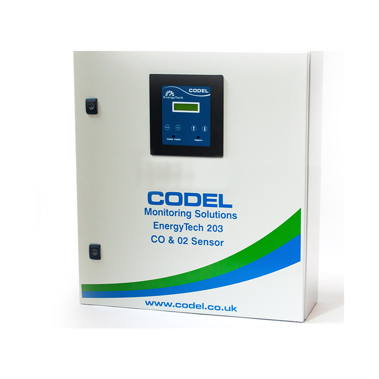
CODEL EnergyTech 203 User manual
CODEL
CODEL TunnelTech 601 User manual

CODEL
CODEL Tunnel Tech 500 Series User manual

CODEL
CODEL Energy Tech 401 User manual

CODEL
CODEL Tunnel Tech 700 Series User manual

CODEL
CODEL TunnelTech 500 Series User manual

CODEL
CODEL GCEM4000 User manual

CODEL
CODEL Energy Tech 301 Guide
Popular Measuring Instrument manuals by other brands

PCB Piezotronics
PCB Piezotronics IMI Sensors TO625B01 Installation and operating manual

Tenmars
Tenmars TM-4001 user manual

Invacare
Invacare CHECK O2 PLUS Assembly, installation and operating instructions

DANOPLUS
DANOPLUS DP-101 user manual

KROHNE
KROHNE OPTISWIRL 4200 quick start

LaserLiner
LaserLiner DampCheck manual