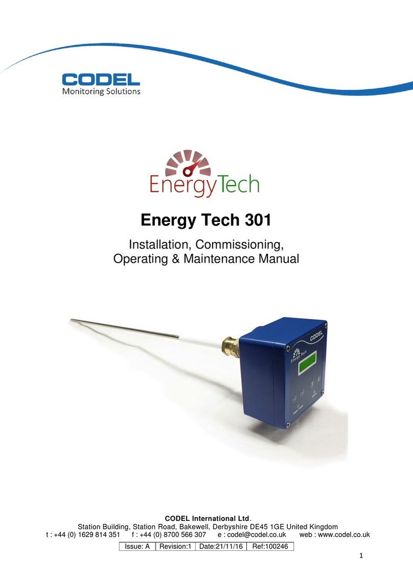
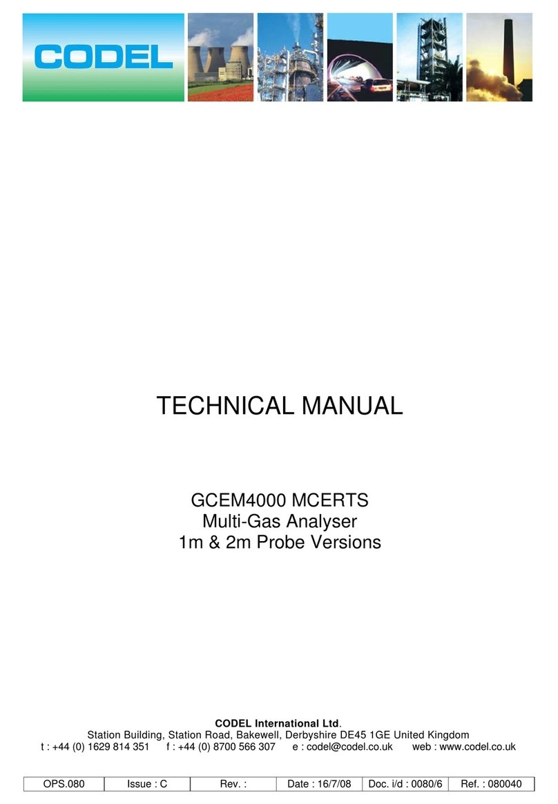
CODEL EnergyTech 203 User manual

Technical Manual
Issue: A
Revision:
Date:29/08/18
Ref: 100416
1
EnergyTech 203
Technical Manual
CODEL International Ltd.
Station Building, Station Road, Bakewell, Derbyshire DE45 1GE United Kingdom

Technical Manual
Issue: A
Revision:1
Date:18/12/17
Ref: 100416
2

Technical Manual
Issue: A
Revision:1
Date:18/12/17
Ref: 100416
3
CODEL International Ltd is a UK company based in the heart of the Peak District National Park at
Bakewell, Derbyshire. The company specialises in the design and manufacture of high-technology
instrumentation for the monitoring of combustion processes and atmospheric pollutant emissions.
The constant search for new products and existing product improvement keeps CODEL one step
ahead. With a simple strategy, to design well-engineered, rugged, reliable equipment, capable of
continuous operation over long periods with minimal maintenance, CODEL has set standards both for
itself and for the rest of the industry.
All development and design work is carried out ‘in-house’ by experienced engineers using proven state-
of-the-art CAD and software development techniques, while stringent assembly and test procedures
ensure that the highest standards of product quality, synonymous with the CODEL name, are
maintained.
High priority is placed upon customer support. CODEL’s dedicated team of field and service engineers
will assist with any application problem to ensure that the best possible use is derived from investment
in CODEL quality products.
If you require any further information about CODEL or its products, please contact us using one of the
numbers below or alternatively visit our web site.
t : +44 (0) 1629 814 351
f : +44 (0) 8700 566 307
web : www.codel.co.uk
CODEL offices, Bakewell, Derbyshire

Technical Manual
Issue: A
Revision:1
Date:18/12/17
Ref: 100416
4

Technical Manual
Issue: A
Revision:1
Date:18/12/17
Ref: 100416
5
Important
The warning signs (and meanings) shown below, are used throughout these instructions and are
intended to ensure your safety while carrying out installation, operation and maintenance procedures.
Please read these instructions fully before proceeding.
Caution, risk of electric shock.
Caution, risk of danger.
Caution, hot surface.
Earth (ground) terminal.
Protective conductor terminal

Technical Manual
Issue: A
Revision:1
Date:18/12/17
Ref: 100416
6

Technical Manual
Issue: A
Revision:1
Date:18/12/17
Ref: 100416
7
Contents
Contents
1. EnergyTech 203 CO and O2 Gas Analysing System.........................................................................9
1.1. Introducton..........................................................................................................................9
1.2. System Operation ............................................................................................................11
1.3. Measurement Cabinet.....................................................................................................12
2. Measurement Principle...........................................................................................................13
3. Summary Specification ..........................................................................................................15
4. Preparing for Installation .......................................................................................................16
4.1. Unpacking..............................................................................................................................16
4.2. Additional Materials.........................................................................................................17
5. Installation .................................................................................................................................18
5.1. General................................................................................................................................18
5.3. Measurement Cabinet.....................................................................................................19
5.3.1. Remote-Mounted Installation....................................................................................19
5.4. Terminal Connections.....................................................................................................20
5.5. Compressed Air Connections ......................................................................................20
6. Commissioning.........................................................................................................................21
6.1. Pre-Commissioning Checks..........................................................................................21
6.2. Normal Start-Up Sequence............................................................................................21
7. Normal Operation.....................................................................................................................22
7.1. Introduction.......................................................................................................................22
7.2. Normal Start-Up Procedure...........................................................................................22
7.3. Modes of Operation.........................................................................................................23
7.4. Key Operation...................................................................................................................24
7.5. Program Tree.....................................................................................................................25
7.6. Operating Mode................................................................................................................26
7.8. Parameter Mode ...............................................................................................................26
7.9. Chamber.............................................................................................................................28
7.9.1. Display Format............................................................................................................28
7.10. Diagnostic Mode...........................................................................................................29
7.10.1. Detector Outputs (CO sensor)...........................................................................30
7.9.2. Thermistor (CO sensor)..................................................................................................30
Technical Manual
Issue: A
Revision:1
Date:18/12/17
Ref: 100416
8
7.9.6. Temperature................................................................................................................31
7.9.8. Fault Condition............................................................................................................32
7.10. Set-Up Mode..................................................................................................................33
7.10.1. Security Code Entry.............................................................................................35
7.10.2. Configure O/P 1 & 2............................................................................................35
7.10.3. Parameters ...........................................................................................................37
7.10.4. Span Factor..........................................................................................................39
7.10.5. Chamber................................................................................................................39
7.10.6. Pressure................................................................................................................40
7.10.7. Calibrate................................................................................................................40
7.10.8. Alarms and Emergency Conditions...................................................................42
7.11. Emergency Shutdown/Isolation Procedure ..........................................................42
8. List of figures........................................................................................................................43
9. Appendix A –Codel EnergyTech 203 DDU Standard ModBus map.......................44
10. Appendix B - Spare parts list........................................................................................47
11. Appendix C - Wiring Connections.............................................................................48

Technical Manual
Issue: A
Revision:1
Date:18/12/17
Ref: 100416
9
1. EnergyTech 203 CO and O2 Gas Analysing System
1.1. Introducton
The EnergyTech 203 carbon monoxide (CO) and oxygen (O2) analyser is the ideal equipment for fine
tuning the air / combustible proportions in a way to improve process efficiency without compromising
safety.
Combustion efficiency is determined by low-level oxygen excess in the flue gas and is limited by the
production of hazardous combustible gas (mainly CO) at low oxygen concentrations. It is thus crucial
to control the O2 excess concentration as well the amount of combustible gas in the flue gas to optimise
combustion. Thanks to the CODEL infrared and zirconia technology, the analyser provides both oxygen
concentration and an accurate measurement of CO in the flue gas. The CODEL system samples the
gas from the critical area through a steel sintered filter mounted in the wall of the chamber.
The filter is back flushed with compressed air at regular intervals to ensure an uninterrupted flow of
sample gas and to minimise maintenance. The sampled gas requires no further pre-conditioning and is
carried via a sample line and pump to the measurement chamber which is equipped with a compact
gas analyser. The measurement chamber is temperature controlled to avoid a build-up of corrosive
condensation. The analyser can re-calibrate automatically to minimise drift and ensure on-going high
performance. The system also includes the facility to be checked manually against bottled audit gases.

Technical Manual
Issue: A
Revision:1
Date:18/12/17
Ref: 100416
10
The mounting arrangements of the EnergyTech 203 are shown in figure 1 below.
Figure 1 : Mounting Arrangements
No
Description
Part No.
Qty
1
Water Drain Solenoid N/C
740.341
1
2
Vacuum Filter
740.342
1
3
Coalescing Filter (99% @ 0.01 Micron)
744.131
1
4
Pressure Transducer
744.048
1
5
Sample Gas Solenoid
740.194
1
6
Span Gas Solenoid
744.341
1
7
ET 200 series Diaphragm Pump
744.133
1
8
Source Head
991.138
1
9
Insulated Heated Sample Chamber
991.790
1
10
Detector Head
991.682
1
11
Oxygen Measurement Probe
Probe: 720.154 / Manifold: 903.352
1
12
Oxygen Probe PCB Enclosure
PCB: 720.153 / Enclosure: 700.044
1
13
24V Power Supply Unit
400.126
1
14
I/O Terminal Rail
1
15
EnergyTech Comms Control PCB
803.534
1
16
Backpurge Solenoid
740.341
1
7
6
5
4
3
2
1
11
12
13
14
8 9 10
6
5
4
3
2
1
15
16

Technical Manual
Issue: A
Revision:1
Date:18/12/17
Ref: 100416
11
1.2. System Operation
A schematic illustration of the CO Gas Analysing System is shown below.
Figure 2: System Schematic
The gas is drawn from the mill outlet duct via a stainless-steel filter through the measurement chamber
using a pump. The arrangement of valves allows three paths ‘A’, ‘B’ or ‘C’.
‘A’ is the normal measurement sample rate which is 1 to 1.5 litre/min.
‘B’ is the flow for the high-pressure air for cleaning the stainless-steel filter.
‘C’ is the flow for the zero/span calibration.
The analyser has several automated operations that allows the system to confirm its own integrity
and perform automated checks reporting any system failures to the end user. The system is designed
to be self-sufficient and will automatically carry out calibrations and filter back purging.

Technical Manual
Issue: A
Revision:1
Date:18/12/17
Ref: 100416
12
1.3. Measurement Cabinet
Figure 3 below is a photograph of the inside of the measurement cabinet.
Figure 3: Inside the Measurement Cabinet

Technical Manual
Issue: A
Revision:1
Date:18/12/17
Ref: 100416
13
2. Measurement Principle
2.1.CO
The analyser comprises an infrared source assembly mounted on one side of the measurement
chamber. On the opposite side of the measurement chamber is the receiver.
The source consists of a small black-body emitter and gas wheel assembly. The wheel is rotated by a
stepper motor at a constant speed of 1Hz. A unique gas cell arrangement enables the transmitted beam
from the source to be periodically interrupted by a gas sample of pure CO, thus enabling active (D1)
and reference (D2) measuring channels to be created.
At the receiver the infrared beam is filtered by a narrow band interference filter corresponding to the CO
absorption band and detected using a lead selenide (PbSe) thermoelectrically-cooled infrared detector.
Mounted at the receiver is a microprocessor that monitors the detector signals and derives the carbon
monoxide concentration from a ratio measurement of the active and reference signals.
The gas sampled via the stainless-steel sintered filter is drawn through the measurement chamber via
an air pump. Periodically, the chamber is isolated from the filter solenoid valve and the filter is back-
flushed to prevent long-term blockage of the filter.
The system can tolerate a very large build-up of pulverised coal at the filter as this build-up is still very
porous to the gas. However, it is essential that the air used to back-flush the filter is dry (less than -
20oC) and oil-free. Water and/or oil will result in the filter rapidly becoming blocked which no amount of
back-flushing will clear.
Every time the system is back-flushed the porosity of the filter is checked. During back-flushing the
compressed air is pulsed to maximise filter cleaning.
At pre-defined intervals the system can be zero calibrated. This calibration is preceded by a back-
flushing of the filter during which time the measurement chamber is back-flushed to remove any traces
of CO. The porosity of the filter is also checked. At any time, span gas can be connected to the system
and the accuracy of the CO monitor verified.

Technical Manual
Issue: A
Revision:1
Date:18/12/17
Ref: 100416
14
2.2.O2
The O2 sensor consists of a well proven zirconium dioxide-based element. The zirconium dioxide
O2 sensor’s working principle measures partial pressure of oxygen in mixture of gases and due to
its unique closed loop measurement system design, it does not require a reference gas. While the
sensor continuously measures the oxygen level, a heartbeat signal is also generated providing an
immediate warning of any failures.
The sensing technology and stainless-steel construction allow these sensors to be used in
environments where extreme pressure, temperature and high humidity are present.
The cell consists of two zirconium dioxide (ZrO2) squares coated with a thin porous layer of platinum
which serve as electrodes. The platinum electrodes provide the necessary catalytic effect for the oxygen
to dissociate, allowing the oxygen ions to be transported in and out of the ZrO2.
The cell assembly is surrounded by a heater coil which produces the necessary 700°C required for
operation. The cell and heater are then housed within a porous stainless-steel cap to filter larger
particles and dust and to protect the sensor from mechanical damage.
depending on the direction of the DC constant current source, the oxygen ions move through the
plate from one electrode to the other, this in turn changes the oxygen concentration and therefore
the oxygen pressure inside the chamber. The pumping is controlled so that the pressure inside
the chamber is always less than the ambient oxygen pressure outside the chamber. A difference
in oxygen pressure across the second ZrO2 square generates a Nernst voltage which is
logarithmically proportional to the ratio of the oxygen ion concentrations. easy single point
calibration can be performed in any known gas including fresh air. The oxygen sensors
can measure over a wide oxygen range (0.1 to 100% O₂).

Technical Manual
Issue: A
Revision:1
Date:18/12/17
Ref: 100416
15
3. Summary Specification
Operating Principle : infrared absorption (CO) / Zirconium dioxide (O2).
Span : *Fully selectable CO 0-1000ppm. O2 0.1 to 30%
Response Time : 120 sec to T90
Gas Species : Carbon Monoxide (CO) and Oxygen O2
Accuracy : ± 10ppm or ± - 2% of span (whichever is the greater).
Resolution : 5ppm. (CO) / 0.1%(O2)
Zero and Span drift : ± 10ppm or 2% of span
Linearity : ± 10ppm or ± - 2% of span (whichever is the greater).
Repeatability : ± 10ppm or ± - 2% of span (whichever is the greater). (CO) /
0.5% (O2)
Ambient Temperature : -20°C or +55°C
Power Supply : AC 110-240V “ min 500W
Construction : RAL7035 Structure powder coated mild steel sealed to IP66
Dimensions : H800 x W800 x D300
Customer Interface
Analogue Outputs : 2 x 4-20Ma current outputs as standard, isolated, 500Ωload
max, fully configurable from keypad (additional optional
outputs available)
Contact Outputs : 1 x volt-free SPCO contact, 50V, 1A max, for data valid
signal.
Alarm Outputs : 2 x volt-free SPCO contact, 50V, 1A max, configurable as
alarm contacts.
Display : 32-character alpha-numeric back-lit LCD.
Keypad : 4-key soft-touch entry.
Communications : RS485 ModBus RTU, baud 9600 4800
Supplies
Compressed Air : 5-7 bar oil free clean compressed air –dry to -20°C
Only required during filter back flush
*Ranges up to 0 –10,000ppm for CO available on request

Technical Manual
Issue: A
Revision:1
Date:18/12/17
Ref: 100416
16
4. Preparing for Installation
4.1. Unpacking
The equipment is normally protected for transportation by an expanded foam packing material. When
unpacking please ensure that smaller items are not discarded with the packing material.
If any items are missing please inform Codel or your local Codel agent immediately.
•Standard supplied items:
: 1 x measurement cabinet
Figure 4: Measurement Cabinet
: 1 x stainless steel filter assembly
Figure 5: Stainless Steel Filter assembly
Whilst the measurement cabinet and filter assembly are essentially interchangeable, the systems are
generally tested as complete units in the factory.

Technical Manual
Issue: A
Revision:1
Date:18/12/17
Ref: 100416
17
4.2. Additional Materials
•heated sample line (when required), together with associated controller. The sample line
should have a minimum I/d of 7mm and should be controlled at a minimum temperature of
60oC.
•compressed air interconnections - The inlet connector to the sample probe is a 10mm
compression fit. However, it is recommended that only the last section (less than 2m) of
the compressed air supply pipe is in minimum 10mm piping. NB. During back-purging
when using 120 litre/min the supply pressure at the monitor should not drop by more than
0.5bar.
•Compressed air supply regulator, dryer and filter. NB. The compressed air supply must not
exceed 7bar as this may result in damage to internal pressure transducers within the
system. For correct operation of the valve arrangements the optimum pressure is 5bar.
•NB. The cable that runs between the solenoid valve on the probe, and the cabinet is not
supplied by CODEL and must be customer supplied.

Technical Manual
Issue: A
Revision:1
Date:18/12/17
Ref: 100416
18
5. Installation
5.1. General
The CO gas analysing system is connected to the duct via a sample line. The measurement cabinet
should be sited as near as possible to the location of the stainless-steel filter assembly on the duct. The
maximum permissible length for the sample line is 100m.
5.2.Site Mounting Flange
Use suitable protective clothing including eye protection. Positive pressure in the duct
will cause hot gases and dust to be vented from the open port.
The site mounting flange that carries the stainless-steel filter assembly should be mounted on the top
or side of the mill outlet duct, as shown in Figure 6. Do not mount the flange on the underside of the
duct.
Figure 6: Filter Assembly Location
Weld the mounting flange and stub pipe assembly (Codel supply) to the mill outlet duct in the selected
position shown in Figure 7.
Do not mount the site flange arrangement directly to the Mill, it must be positioned on
the duct from the Mill, failure to do so will result in failure of the sample probe.
Figure 7: Mounting Flange & Stub Pipe Assembly
✓
✓
✓
Duct Wall
50mm
clearance
Mounting flange &
stub pipe assembly

Technical Manual
Issue: A
Revision:1
Date:18/12/17
Ref: 100416
19
5.3. Measurement Cabinet
5.3.1. Remote-Mounted Installation
The rear of the measurement cabinet is pre-drilled to enable remote mounting; mounting hole details
are shown below in Figure 8. Connect the sample line at one end to the measurement cabinet and at
the other end to the stainless-steel filter assembly via the ¼’’ BSP/10mm compression fittings provided.
Remember that the maximum permissible length for the sample line is 100m.
Figure 8: Measurement Cabinet
800
300
800
760
Mounting Holes 4 x M8 bolts (customer supply)
760

Technical Manual
Issue: A
Revision:1
Date:18/12/17
Ref: 100416
20
5.4.Terminal Connections
Live
1
Neutral
2
Earth
3
A
4
B
5
NO1
6
W1
7
NC1
8
NO2
9
W2
10
NC2
11
NO3
12
W3
13
NC3
14
+mA1
15
0mA1
16
+mA2
17
0mA2
18
24v switched
19
0v return
20
For more detailed board connections, see Appendix C
5.5.Compressed Air Connections
The compressed air must be clean, oil-free and dry to -20oC. The compressed air supply is connected
to the stainless steel filter assembly via a 10mm compression connection. The maximum air flow
required is 120 litre/min @ STP.
Prior to connecting the air supply line to the measurement cabinet it is advisable to purge the line for
approximately 1 minute to remove any fine dirt particles that could otherwise block the filter.
Mains electrical connections
RS485
Data valid
Volt free contact
Alarm 1
Volt free contact
Alarm 2
Volt free contact
current output 1
4-20mA
current output 1
4-20mA
back purge solenoid connection
RS485
Data valid
Volt free contact
Alarm 1
Volt free contact
Alarm 2
Volt free contact
current output 1
4-20mA
current output 1
4-20mA
back purge solenoid connection
Data valid
Volt free contact
Alarm 1
Volt free contact
Alarm 2
Volt free contact
current output 1
4-20mA
current output 1
4-20mA
back purge solenoid connection
Alarm 1
Volt free contact
Alarm 2
Volt free contact
current output 1
4-20mA
current output 1
4-20mA
back purge solenoid connection
Alarm 2
Volt free contact
current output 1
4-20mA
current output 1
4-20mA
back purge solenoid connection
Current output 1
4-20mA
current output 1
4-20mA
back purge solenoid connection
Current output 2
4-20mA
back purge solenoid connection
Table of contents
Other CODEL Measuring Instrument manuals

CODEL
CODEL EnergyTech 100 Series Guide

CODEL
CODEL DCEM2000 User manual

CODEL
CODEL TunnelTech 601 User manual

CODEL
CODEL Energy Tech 301 Guide

CODEL
CODEL TunnelTech 500 Series User manual

CODEL
CODEL Energy Tech 401 User manual

CODEL
CODEL GCEM4000 User manual

CODEL
CODEL Tunnel Tech 500 Series User manual

CODEL
CODEL Tunnel Tech 700 Series User manual
Popular Measuring Instrument manuals by other brands

Tenmars
Tenmars TM-740 user manual

RT Systems
RT Systems TM3 Installation and user manual

ENDA
ENDA ETS1410 user manual

Precision Digital Corporation
Precision Digital Corporation PROVU Series instruction manual

Endress+Hauser
Endress+Hauser Stamolys CA71SI Series operating instructions

Grandway
Grandway FHO2000 OTDR quick guide