COFFEtek Neo + User manual

Neo +
TECHNICAL MANUAL
2GBNCEFB50 NEO T/GB/EFB/73
2GBNC4EFB51 NEO T/GBEFB73/RBR
Issue 1
81066680

COFFEtek Ltd
NEO +
Issue 1
10/10/20
2
NEO +
TECHNICAL MANUAL
CONTENTS page
FOREWORD ..................................................................................................................................4
SAFETY WARNINGS.....................................................................................................................6
NEO - EXTERIOR...........................................................................................................................7
NEO- INTERIOR.............................................................................................................................8
SECTION 1 TECHNICAL INFORMATION......................................................................................9
INTRODUCTION ................................................................................................................................................9
CABINET FRONT.........................................................................................................................................10
CABINET INTERIOR....................................................................................................................................11
WATER SYSTEM.............................................................................................................................................12
HOT WATER SYSTEM................................................................................................................................12
COLD WATER SYSTEM..............................................................................................................................12
SECTION 2 INTERNAL KEYPAD FUNCTIONS...........................................................................16
SECTION 3 PROGRAMMING...................................................................................................... 18
PROGRAM FUNCTIONS.................................................................................................................................20
PROGRAMMING SEQUENCE OF OPERATIONS .........................................................................................21
MENU OPTIONS..............................................................................................................................................22
Output Test...................................................................................................................................................22
Input Test......................................................................................................................................................22
Set Product Constants .................................................................................................................................23
Machine Status.............................................................................................................................................23
Set Dry Vends ..............................................................................................................................................24
Configure Machine .......................................................................................................................................25
MDB Config..................................................................................................................................................31
EVA-DTS Config...........................................................................................................................................33
Engineers Code (4444) ................................................................................................................................34
USB Actions .................................................................................................................................................34
Economy Mode.............................................................................................................................................35
Depressurise Coffee Brewer........................................................................................................................37
SECTION 4 INSTALLATION & COMMISSIONING......................................................................38
INTRODUCTION ..............................................................................................................................................74
SAFETY WARNINGS.......................................................................................................................................75
FROST WARNING...........................................................................................................................................76
SERVICES REQUIRED....................................................................................................................................76
INSTALLATION ...............................................................................................................................................76

COFFEtek Ltd
3
10/10/20
Issue 1
NEO +
LOCATION...................................................................................................................................................77
LEVELLING..................................................................................................................................................77
CONNECTING THE WATER SERVICES........................................................................................................78
CONNECTING THE ELECTRICAL SERVICES..............................................................................................79
COMMISSIONING............................................................................................................................................80
DAILY HYGIENE..............................................................................................................................................81
Cleaning (Instant & Espresso)......................................................................................................................81
WEEKLY HYGIENE.........................................................................................................................................82
Cleaning (Tea)..............................................................................................................................................82
Cleaning (Espresso).....................................................................................................................................83
Cleaning (Instant).........................................................................................................................................83
Filling Procedure (Instant & Tea)..................................................................................................................84
Filling Procedure (Espresso)........................................................................................................................85
FAULT FINDING GUIDE.............................................................................................................. 87
SECTION 5 SETTING UP A NEW OR REPLACEMENT CONTROL BOARD .........89
SECTION 6 SCHEMATICS & EXPLODED PARTS DIAGRAMS .................................................91

COFFEtek Ltd
NEO +
Issue 1
10/10/20
4
FOREWORD
1. The information contained in this manual is applicable to the Neo Touch beverage machine.
2. The machine described in this manual is the Neo Espresso version. Due to customer requirements,
however, some features may vary from the one described, e.g. extras fitted, variations in
programming etc.
3. Maintenance of the beverage machine must only be undertaken by personnel who are authorised
and suitably qualified.
4. The Manufacturer reserves the right to make changes without notice to the design of the beverage
machine, which may affect the information contained in this manual.

COFFEtek Ltd
5
10/10/20
Issue 1
NEO +
SPECIFICATION
Dimensions
Height 1830 mm
Depth 710 mm
Width 700 mm
Weight 140Kg
Temperature Range
Temperature 1ºC Min - 40ºC Max
Cup Information
70 mm - 600 cup capacity
73 mm - 500 cup capacity
78 mm - 350 cup capacity
Electrical Services
Supply voltage - 230v Ac, 50Hz, single phase
Current Rating - 16A UK, 10 Amp version available for NZ and Australia.
The fused electrical supply must be terminated at a safety isolator switch, which provides a contact
separation of at least 3mm. The isolator should be located within 1m of the beverage machine.
Water Services
Water pressure - 0.1 MPa min 0.8 Mpa max
15mm diameter water mains supply, terminating at a convenient stop tap located within 1m of the
beverage machine with an appropriate water blocker mounted between the machine and the water
source. A 15 mm double back check valve, with inspection port, should be fitted prior to the flexible
hose. The water supply should be fitted with the appropriate water blocker.
Chiller Unit
Weight - 20Kg
Refrigerant - R134A
Refrigerant Weight - 85gms
Carbonator Unit
Weight - 26.5Kg
Refrigerant - R134A
Refrigerant Weight - 155gms

COFFEtek Ltd
NEO +
Issue 1
10/10/20
6
SAFETY WARNINGS
1. Maintenance of the beverage machine is only to be undertaken by trained personnel who are
fully aware of the dangers involved and who have taken adequate precautions, e.g.
ensuring that, whenever possible, the beverage machine is isolated from the mains electrical
supply.
2. Lethal voltages are exposed when any panel inside the cabinet is removed and the mains
electrical supply is available (i.e. on/off switch is overridden). The mains electrical supply is
maintained to the Carbonator even when the door is open.
3. The beverage machine must be earthed.
4. Keep clear of the Brewer Unit when it is indexing.
5. The beverage machine is a heavy item. Ensure that sufficient personnel are available for
manoeuvring and transporting the machine. Use proper lifting procedures and equipment.
6. The water in the heater tank, and the tank itself, are hot enough to scald or burn, even some
time after the machine has been switched off. The water heater tank must be drained, filled
with cold water and drained again before any attempt is made to handle it or any of its
associated parts.
7. The water available from the option shower head cleaning attachment is hot enough to scald
or burn. Appropriate care must be taken when using this attachment.
Note: Initially the water flowing from the attachment will be cool but will rapidly become
extremely hot.
8. The Controller Board is fitted with a lithium battery. Abuse of this type of battery can lead to
overheating, venting, explosion, release of potentially hazardous materials and spontaneous
ignition.
9. The lithium battery must not be charged or connected to any other source of power.
The battery must not be short-circuited or forced to discharge its stored energy. The battery
must not be subjected to physical damage or overheating. If the Controller Board is to be
replaced, it must be handled with care, taking all practical anti-static precautions.
9. Care must be taken to protect the beverage machine from frost. Do not attempt to operate
the machine if it becomes frozen. Contact the nearest service agent immediately. Do
not restore the machine to operational use until it has been checked and approved for use by
the service agent.
10. THE APPLIANCE CAN BE USED BY CHILDREN AGED FROM 8 YEARS AND ABOVE AND
PERSONS WITH REDUCED PHYSICAL, OR MANTAL CAPABILITIES OR LACK OF
EXPERIENCE AND KNOWLEDGE IT THEY HAVE BEEN GIVEN SUPERVISION OR
INSTRUCTION CONCERNING USE OF THE APPLIANCE IN A SAFE WAY AND
UNDERSTAND THE HAZARDS INVOLVED. CHILDREN SHALL NOT PLAY WITH
APPLIANCE. CLEANING AND USER MAITENANCE SHALL NOT BE MADE BY CHILDREN
WITHOUT SUPERVISION.
11. Replacement of the Type Y mains cable requires special tools. Should the cable become
damaged, a trained person from an approved service agent must only carry out replacement.
12. ENSURE THE MACHINE LOCATION HAS BEEN RISK ASSESSED. IT IS THE
RESPONSIBILITY OF THE INSTALLER TO INFORM THE SITE’’S HEALTH & SAFETY
REPRESENTATIVE OF THE POTENTIAL RISK TO USERS OF THIS EQUIPMENT.

COFFEtek Ltd
7
10/10/20
Issue 1
NEO +
1
2
3
5
6
Neo + –Exterior
1. Video Screen
2. Customer Interface
3. Door lock
4. Coin Entry
5. Cup Station
6. Coin Reject

COFFEtek Ltd
NEO +
Issue 1
10/10/20
8
1
3
5
6
8
2
4
7
9
1
0
1
1
1
2
Neo+ - Interior
1. Main Switch
2. Internal/Service Keypad
3. Canisters
4. Cup Turret
5. Mixing Bowls
6. Tea Brewer
7. Cup Drop Unit
8. Dispense Head
9. Cup Catcher
10. Coin Mechanism Cover
11. Drip Tray and Grill
12. Cash Box

COFFEtek Ltd
9
10/10/20
Issue 1
NEO +
Section 1
Technical Information
INTRODUCTION
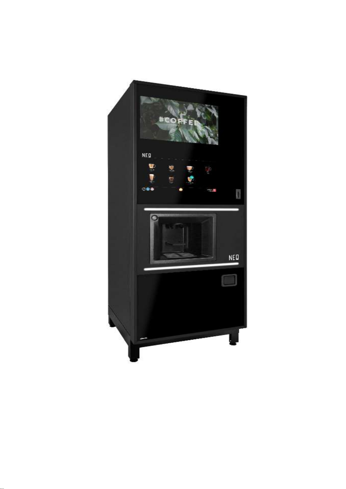
1. The Neo + is a coin-operated, microprocessor-controlled beverage machine that dispense a
range of hot and cold drinks in response to touch screen selections.
2. This manual uses the Espresso version as the basis for examples. Where significant
differences between versions exist, this will be highlighted in the main body of the
document. Due to customer requirements, however, some features may vary from those
described, e.g. extras fitted, variations in programming etc.
3. Three options are available to add a cold drinks capability to machines in the Neo range.
An optional chiller allows the addition of a cold-water selection. A chiller incorporating a pair
of syrup pumps allows for the addition of two flavoured cold drinks, whilst a carbonator
provides the option of two flavours of still and carbonated drinks in addition to cold water.
4. Cups from a cup drop mechanism are dispensed to contain the drinks. However, a key-
operated jug facility is also provided.
5. Selection is made on a touch screen panel that shows status and drink selection
information.
6. The status of the machine may be monitored, and the configuration altered, by accessing a
menu of program options on the external screen. Each option comprises a number of sub-
options, the settings of which can be altered.
7. Dependent on software setting, the feature of the Neo beverage machines is the mobile
dispense head which moves the head to a parked position away from the cup port after
each drink is vended, preventing the possibility of any residue from the previous drink
dripping into the next one. The dispense head is fitted with two groups of nozzles, one for
hot drinks and one for cold. Upon selection, the required group is moved into place above
the cup port.
8. The Neo machines require a single-phase 240V electrical mains supply from a domestic
13A outlet, and a cold-water supply from the domestic cold water main. These services
enter the machine at the rear of the cabinet.
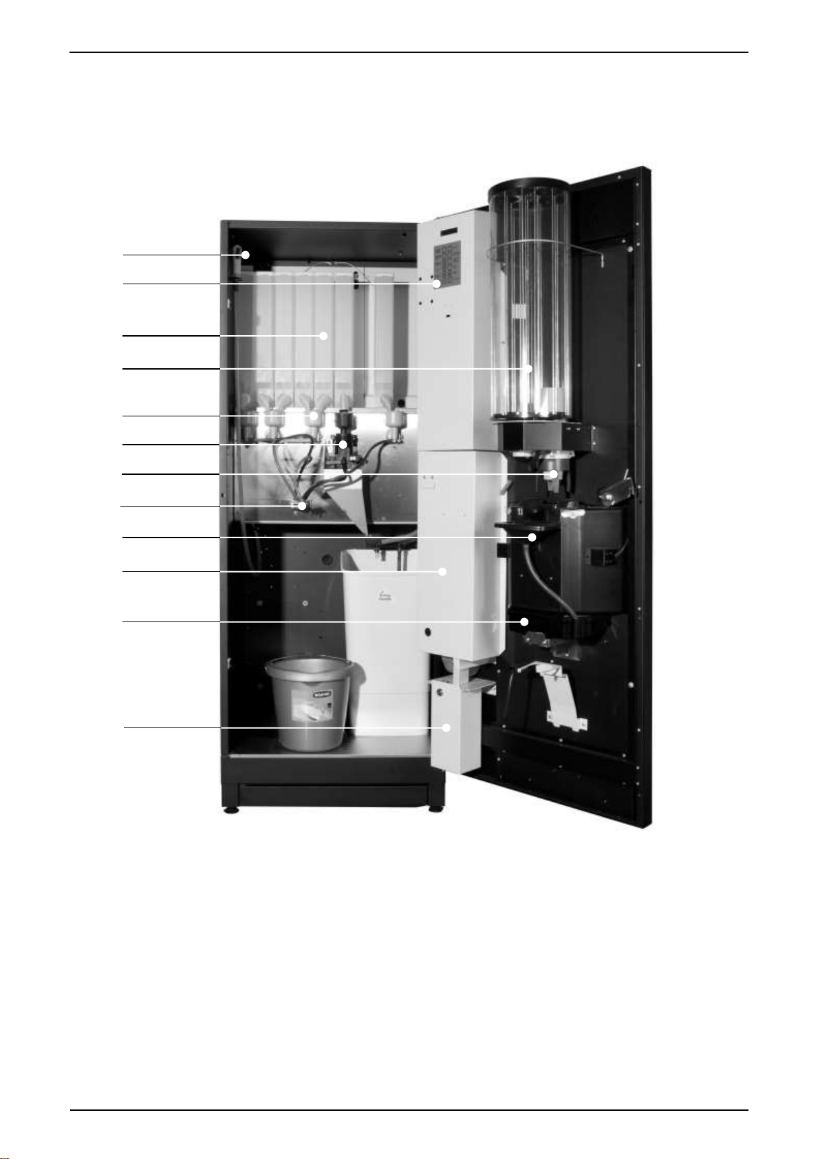
9. The operational components which form a Neo beverage machine are housed in a metal
enclosure, access to which is gained by a swivel door secured by a key operated locking
mechanism. Turning the key in the lock releases a door handle, which allows the locking
mechanism to move to the unlocked state and the door to be opened. With the door open
the mains isolation switch for ON/OFF operation of the machine is visible in the top left
corner of the machine.
10. Equipment inside the cabinet is arranged in two sections: front and rear. On opening the
door, the Operator is immediately faced with those items of equipment to which he or she
requires access, e.g. Ingredient Canisters, Cup Turret, Coin Mechanism, CO2 Bottle, Waste
Trays, etc. The remaining items of equipment, i.e. Water Heater, Valves, Electrical and
Electronic components, etc, to which specifically the Engineer requires access (and from
which the Operator must be shielded) are located behind the Ingredient Canisters and
Whipper Motor and Dispense Head Assembly panel, at the rear of the cabinet.

COFFEtek Ltd
NEO +
Issue 1
10/10/20
10
CABINET FRONT
13. The front of the cabinet door is constructed of one single sheet of smoked glass behind
which are located a single board PC attached to a touch panel which will show drinks
selections when pressed, progress of the vend and can also run standby videos or
pictures/branding. There is also a USB connection.
14. The Cup Drop Assembly, Coin Mechanism, Controller Board and Cup Station are fitted to
the rear of the cabinet door.
15. Ingredient canisters are located on a shelf approximately halfway up the cabinet. At the
front of the shelf is a duct assembly to which an extractor fan is connected. The fan pulls air
from the extract duct, which in turn removes steam/moist air from the mixing systems,
which are located on a vertical panel below the canister shelf. The moving dispense head
protrudes through and is fastened to this vertical panel and in the case of the fresh brew
versions this vertical panel also provides the mounting for the fresh brew units.
16. If fitted, the optional cold drinks unit is in the lower left-hand corner of the cabinet.
In the case of a carbonated unit, the CO2 cylinder is placed in the lower right-hand corner of
the cabinet with the two syrup containers at its side. A gas regulator with associated
pressure gauge is fitted to the CO2cylinder in addition to an ordinary cylinder pressure
gauge. The regulator is set to give an output pressure of 50 psi.
17. On the Fresh Brew versions, a large plastic waste bucket is located underneath the Brewer
Unit(s), in addition to the smaller one placed at the front of the cabinet, beneath the Cup
Station (when the door is closed). Water heater and carbonator overflow pipes, and a waste
level probe, are directed into the smaller bucket. When the waste liquid in the bucket(s)
reaches the level sensor probe, the water supply inlet is shut off and the machine is
rendered inoperable.

COFFEtek Ltd
11
10/10/20
Issue 1
NEO +
CABINET INTERIOR
18. Access to the components and equipment in the rear section of the cabinet is obtained by
removing the ingredient canisters and the relevant back panel.
19. Cold water mains supply enters the cabinet through an aperture in the rear panel and
connects to a twin chamber inlet valve for the hot water supply. There is also a similar twin
chamber inlet valve dedicated to the cold-water supply. This is fitted only in the case where
a cold drinks system is required.
20. A length of tubing takes the water supply from the inlet valve into the water heater tank,
located at the top of the cabinet. Hot water in the correct quantity is then directed from the
tank to the appropriate mixing bowl via a solenoid operated dispense valve. A dispense
valve is associated with each ingredient. Any overflow from the tank is directed into the
waste bucket via an overflow tube. Fitted to this tube is a high temperature cut-out (or two
cut-outs, depending on the model) which, when operated, cuts off the electrical supply to
the heater in the tank. The cut-out must then be reset to restore the supply. Another length
of tubing facilitates draining of the heater.
21. The Carbonator is provided with three inputs: cold water from the inlet valve; two types of
syrup, pumped from the syrup containers; and carbon dioxide from the CO2cylinder. Still or
carbonated water and syrup are taken from the carbonator, via separate tubes, to the
dispense head.
22. A level probe is fitted to the rear of the cabinet door and a similar device is in the fresh brew
waste container. When the door is closed these devices act as contact probes allowing the
units control system to monitor the liquid level in the waste containers.
23. Two printed circuit boards are fitted to the top right-hand side of the cabinet rear panel: the
DC Remote Input/Output Board (DC RIO) and the Power Supply Unit (PSU). The DC RIO
Board provides the high current drives to operate the output devices (valves, motors, etc.)
in response to signals from the Controller Board.
24. A solid-state relay, located beneath the printed circuit boards, pulses current to the heater
in response to signals from the DC RIO Board. The DC RIO Board receives signal from the
Controller Board via an I2C link. The temperature of the water in the boiler is measured by
the Controller Board using an NTC thermistor mounted at the end of a stainless-steel probe
immersed in the hot water tank.

COFFEtek Ltd
NEO +
Issue 1
10/10/20
12
WATER SYSTEM
25. The cold-water mains supply enters the machine via a double-solenoid operated inlet valve
at the rear of the cabinet. This valve controls the flow of water to the unit’s hot water tank.
If an optional cold drink system is fitted, a separate inlet valve is used to connect it to the
mains water supply. In this eventuality a special ‘Y’ shaped mains water supply hose is
required.
26. Fitted to the mains water line to the vending machine should be an appropriate water
blocker.
HOT WATER SYSTEM
27. Water is supplied via the Hot Inlet valve to the heater tank where it is heated to the required
temperature by a heating element in the tank. Water temperature is controlled by a
combined temperature and level probe assembly in the tank which causes the supply to the
heater to be removed when the pre-set temperature is reached. The probe assembly also
acts as a level sensor, causing the Hot Inlet valve to open when the water in the tank falls
below a pre-set level. The probe (i.e. the input device) is monitored by the Controller
Board, and the water heater and Hot Inlet valve (i.e. the output devices) are controlled by
the DC RIO Board in response to signals from the Controller Board.
28. Depending on the type of hot drink selected, hot water from the heater tank is fed via
solenoid operated dispense valves to the appropriate mixing bowl or Brewer Unit container.
Ingredients and water are mixed in exact quantities in the mixing bowl and then directed to
the dispense head. Similarly, water and ingredient are brewed in exact amounts in the
Brewer Unit and then directed to the dispense head.
29. The resettable cut-out sensor(s), mounted on the boiler overfill tube, cuts off the electrical
supply to the tank heater circuit if the water in the tank starts to boil. Additionally, if the fluid
level in the overflow waste bucket rises above a pre-set level, it is detected by a level probe
and reported to the Controller Board, which responds by closing the inlet valve via the DC
RIO Board and rendering the machine inoperable.
COLD WATER SYSTEM
30. Water is supplied from the Cold Inlet valve to the chiller or carbonator unit (if fitted) via a
pressure regulator. The chiller / carbonator provides either cold still water or cold
carbonated water (carbonator only). The selected type of water (still or carbonated) is
controlled by solenoid operated dispense valves. Flavoured syrup, if available, is added to
the drink by means of oscillating pumps.

COFFEtek Ltd
13
10/10/2020
Issue 1
NEO +

COFFEtek Ltd
NEO +
Issue 1
10/10/2020
14
COIN
MECHANISM
MPU RIO
POW ER
SUPPLY
I
2
C LINK
OPTIONAL
INTERFAC E
BREWER
INDEX
DISPENSE
HEAD
C USTOMER
KEYPAD
DISPLAYDISPLAY
C UP SENSOR
USER JUG KEY
C UP THROAT
C AROUSEL INDEX
TEMP/LEVEL SENSOR
WASTE LEVEL SWITC H
C ARB LEVEL PROBE
MOTORS
VALVES
SOLENOIDS
HEATER SSR
12V 24V RETURN
24V DC
VALVES
HEATER SSR
EXTRAC T FAN
MOTORS
SOLENOIDS
240V AC
12V
FIG 1.2 ELECTRICAL & ELECTRONIC SYSTEM –FUNCTIONAL DIAGRAM

COFFEtek Ltd
15
10/10/2020
Issue 1
NEO +
This page is intentionally blank.

COFFEtek Ltd
NEO +
Issue 1
10/10/2020
16
Section 2
Internal Keypad Functions
FIG 2.1 NEO INTERNAL KEYPAD
1. The internal keypad provides the facility to carry out a number of frequently required
machine functions without the necessity to enter any of the user programs.
2. In most cases a single press of the key initiates the function associated with each button.
If a further key press is necessary to end the action, it will be the ESCAPE key.
ADVANCE
COFFEE BREWER
MDB MECH
DISPENSE
COIN
BREWER
FLUSH
FLUSH
SYRUP 1
PRIME
SYRUP 2
PRIME
PROG
ADVANCE
TEA BREWER
CUP
TEST
4
9
5
0
6
1
2
7
3
8
ENTER
ESC

COFFEtek Ltd
17
10/10/2020
Issue 1
NEO +
3. The functions available from the internal keypad are as follows:
(a) Advance Coffee Brewer.
If a coffee brewer is fitted, a single depression of this key will cause the brewer unit to
index to its next position in the cycle. The purpose of this function is to allow the brewer
to be locked prior to a flush cycle so that cleaning agents can be added.
(b) MDB Mech Dispense Coin.
This key provides a method to empty the change tubes of an MDB coin mechanism,
which does not itself possess the necessary buttons to do so. On pressing the key, the
external display will change to: -
EMPTY TUBE
£0.05 ENTER OR ESC
The currency value shown will be that of the lowest value coin tube in the coin
mechanism. The function of the EXTERNAL keys will change as described in section 3
to allow actions to be performed on either the internal or external keypad. Pressing
ENTER will cause a coin to be dispensed from the currently selected tube. Pressing the
(UP) or (DOWN) selects the next/previous coin tube. Repeated use of the (UP),
(DOWN) & ENTER keys enables all tubes to be emptied. Pressing the ESCAPE key
ends the process.
(c) Brewer Flush
This key provides the means to initiate a flush cycle of the fresh brew units. A single
press of this key will initiate a cleaning cycle for all brewers fitted to the machine
simultaneously. In the case of the instant version this function is redundant.
(d) Syrup 1 Prime
Manually controls the pump associated with flavored syrup number 1. The first press
turns on the pump; a second press turns it off again. Pressing the ESC key will also turn
off the pump.
(e) Syrup 2 Prime
Manually controls the pump associated with flavored syrup number 2. The first press
turns on the pump; a second press turns it off again. Pressing the ESC key will also turn
off the pump.
(f) Prog
This key activates the code entry sequence required to access the protected levels of
the machine control programs. See section 3.
(g) Advance Tea Brewer.
If a tea brewer is fitted, a single depression of this key will cause the brewer unit to index
to its next position in the cycle. The purpose of this function is to allow the brewer to be
locked prior to a flush cycle so that cleaning agents can be added.

COFFEtek Ltd
NEO +
Issue 1
10/10/2020
18
(h) Cup Test
Causes a cup to be dispensed by the cup drop mechanism. The cup carousel will not
index, unless a selection is made, or a cup test performed. This reduces the possibility of
damage; prevents damage to the carousel occurring because the cup stack has been
pushed up from below causing a false out of cups signal to the control board.
Section 3
Programming- Internal
1. The Neo vending machine has a configuration program to allow the behaviour and function
of the machine to be changed to meet a customer’s requirement. While many of the
functions are accessed via the Touch Screen, for ease of use while accessing the machine
internals several functions are available via the internal keypad. Access is protected by
means of a four-digit code. The facilities available are shown below:
(1) Engineer level access
•Full access to all features
•Factory default code 4444
ACCESSING THE USER PROGRAMS
2. The programs are accessed by pressing key 5 (PROG) on the INTERNAL keypad.
The EXTERNAL display will then prompt for input of a four-digit entry code. The code is
input using the numbers printed on the keys of the INTERNAL keypad.
(2) After pressing the PROG key, the display will change to: -
PLEASE ENTER
ACCESS CODE
(3) Use the numbered keys on the INTERNAL keypad to enter the correct code. It is not
necessary to press ENTER. The code will be checked on entry of the fourth digit.
Three attempts are allowed before the PROG key must be pressed again. On entry of
a valid code the display will change to the menu heading appropriate to the level of
access.
(4) In the event that the code has been lost or when fitting an un-programmed
replacement board, it is necessary to complete the circuit between the two pins of the
two-pin header labelled ENG LINK on the Control Board. These bypasses the entry of
the four-digit code, giving the engineer level access to the bootloader and the
engineers mode. If the ENG LINK is left in place during power up, the machine
will start straight into the engineer’s program asking whether you want to use
the bootloader or bypass straight into the engineer’s mode.
NOTE REGARDING POWER UP PROBLEMS
3. The Neo electronics control system has two major elements. These are the Control Board
and the DC RIO board. The two boards communicate via a three wire Inter Integrated
Circuit bus (I2C bus). Some faults affecting the I2C bus or Control Board configuration can
result in persistent system resets. To allow recovery / diagnosis from such situations, the
control system provides an Access Window to a special ‘safe mode’ shortly after power is
switched on. It is possible to enter the engineer’s mode during this window.

COFFEtek Ltd
19
10/10/2020
Issue 1
NEO +
Some configuration faults related to uninitialized boards do not allow the system to get even
this far through start up, in which case it is necessary to insert the ENG LINK before switching
the power on. In this case the machine will boot straight into the engineer’s program.
In both cases the I2C bus linking the electronics boards is disabled. Without communication
between the DC RIO board and the Control board the OUTPUT TEST facility is ineffective,
and the state of some inputs will be misreported in the INPUT TEST routines. As a reminder to
this effect the sound associated with a key press is truncated to a very short pip rather than a
beep.

COFFEtek Ltd
NEO +
Issue 1
10/10/2020
20
PROGRAM FUNCTIONS
4. The following table shows the functions available and the access level required to use them
within the Neo configuration program:
FUNCTION
ENGINEER
OUTPUT TEST
•
INPUT TEST
•
SET PRODUCT CONSTS
•
MACHINE STATUS
•
SET DRY VEND MODE
•
CONFIGURE MACHINE
•
MDB CONFIG
•
EVA-DTS CONFIG
•
ENGINEERS CODE
•
USB ACTIONS
•
ECONOMY MODE
•
DEPRESSURISE C’ BREWER
•
Other manuals for Neo +
1
This manual suits for next models
4
Table of contents
Other COFFEtek Vending Machine manuals
Popular Vending Machine manuals by other brands

Laurel Metal Products Incorporated
Laurel Metal Products Incorporated 2599 Operation and service manual

Saeco
Saeco D.A. 8P Standard Operation and maintenance

MEI
MEI Cashflow 690 series Quick reference card

EVOCA
EVOCA Opera Installation - use - maintenance

WAYFARER
WAYFARER TGX150 Service manual

Azkoyen
Azkoyen TEMPUS III Technical manual