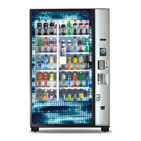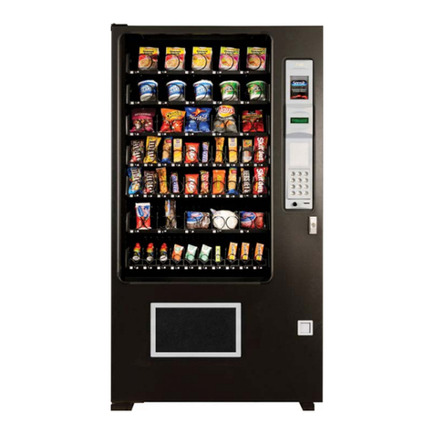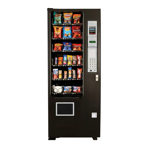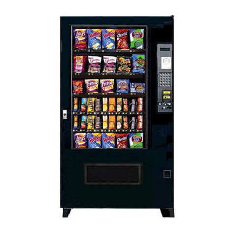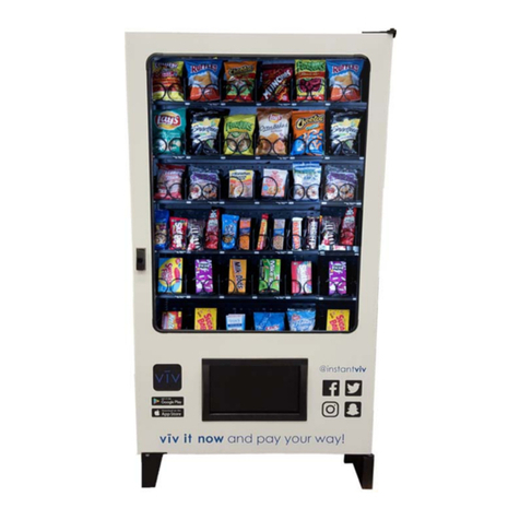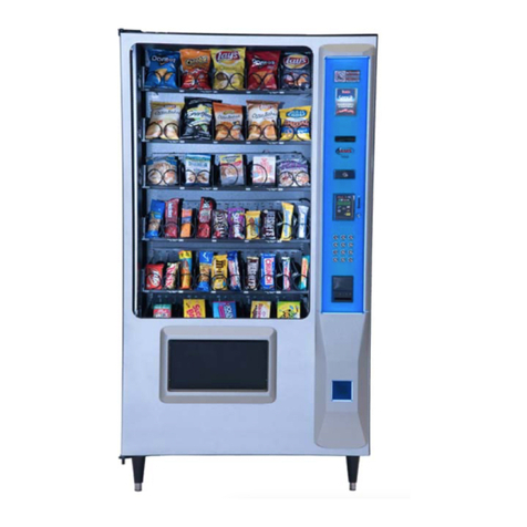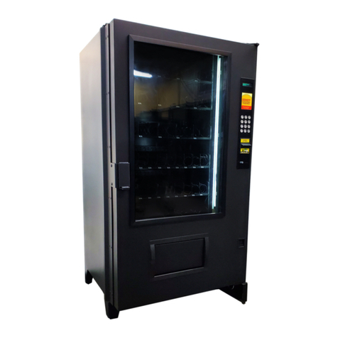
AMS SENSIT II GLASS FRONT VRM VENDOR L0086, Rev. D
1-1
1.0 INTRODUCTION
Congratulations on the purchase of your new AMS
Sensit II 39-VRM vendor. The VRM Snack and Visi-Combo
Vendors are versatile, high-capacity vending machines.
The VRM vendor is designed, tested, and built to provide
years of reliable, low-maintenance service in both indoor
and outdoor environments. A fully insulated cabinet, DEX
data capability, and flexible product configuration are just
some of the many standard features built into every AMS
merchandiser.
1.1 SENSIT II SYSTEM
Your vendor is equipped with the Sensit II system. The
Sensit II system is a patented vend-sensing system that
detects when products fall into the delivery bin. Basically, a
plane of infra-red light beams is created across the top of
the delivery bin, and the Sensit II system can detect when
any part of the light has been blocked by a passing product.
Using this technology, the vendor “knows” when your
customer gets the product. The Sensit II system has
several important benefits:
1.1.1 Guaranteed Delivery
If, after one revolution, the product hangs up or an
opening was missed in loading, the helix will rotate three
additional half-revolutions to make sure the product is
delivered. No more hitting or shaking the vendor to get
products that did not fall!
1.1.2 Instant Refund
If the customer does not receive a product, he can
receive a full refund by pressing the coin return, or he can
select another product. No more refund requests!
1.1.3 Automatic Helix Adjustment
With the Sensit II system, the helix stops as soon as
the product falls. It is no longer necessary to adjust the
home position of the helix for each different package. In
fact, different packages can be loaded in the same column.
No more double vending!
1.1.4 Additional Benefits:
1. Opening the delivery bin door will not affect the Sensit II
system. The sensors are located above the delivery bin
and will not be blocked by the door. Product that falls
while the door is open will still pass through the beam.
2. Shining a light at the detector will not allow vandals to
receive free product. Any tampering which changes the
precise amount of light normally received will be treated
as a successful vend, resulting in the vandal losing his
money.
3. Disabling or blocking the sensor will not allow vandals to
receive free product. The Sensit II system must be
receiving the normal amount of light before the vendor
will dispense any product.
4. Opening the door of a cold vendor will cause some
condensation to form inside. The Sensit II system will not
allow vending until this fogging clears, normally within a
few minutes of closing the door.
1.2 MODEL IDENTIFICATION
When requesting service, replacement parts or
technical assistance, please refer to the Vendor Serial
Plate (as show in Figure 1.1, Vendor Serial Plate). The
plate is located on the inside of the upper left or right of the
window, or on the outside of the door on the lock side. The
information contained on this plate is necessary to
determine what parts, kits, or maintenance should be
applied to your specific model.
Figure 1.1 Vendor Serial Plate
1.2.1 Model Number Breakdown (refer to Figure 1.1)
AMS 39 - VRM
Manufacturer Cabinet Width Type
1.2.2 Serial Number and Date Code Breakdown (refer to
Figure 1.1)
Sequential Production Number Production
Run Number
1203 - 1010 - B 2
Quarter (ABCD) Year
Example: 1203-1010-B 2 would be translated as
sequence number 1203 of production run 1010,
manufactured in the second quarter (B) of 2005.
The Production Run Number of machines built in the
U.S. starts with the number 1 or any odd number. The
Sequential Production Number of machines built in Mexico
starts with the number 0 or any even number.
1.3 GENERAL SPECIFICATIONS
1.3.1 Operating Environment
The AMS Model 39-VRM Vendor is designed for
indoor or outdoor use.
