Cogentix Medical Urgent PC User manual

0344
UPC 200-B
Neuromodulationssystem • Sistema de neuromodulación •
Système de neuromodulation percutanée • Sistema di neuromodulazione
• Neuromodulatiesysteem • Sistema deneuromodulação •
Nöromodülasyon Sistemi
URGENT®PC STIMULATOR
Instructions for Use................................................. 3
URGENT®PC-STIMULATOR
Gebrauchsanweisung ...................................................................... 22
ESTIMULADOR URGENT®PC
Instrucciones de uso........................................................................ 44
STIMULATEUR URGENT®PC
Mode d’emploi................................................................................. 64
STIMOLATORE URGENT®PC
Istruzioni per l’uso ........................................................................... 84
URGENT®PC-STIMULATOR
Instructies voor gebruik ................................................................. 104
ESTIMULADOR URGENT®PC
Instruções de utilização ................................................................. 126
URGENT®PC STIMÜLATÖRÜ
Kullanım Kılavuzu .......................................................................... 146

English
3
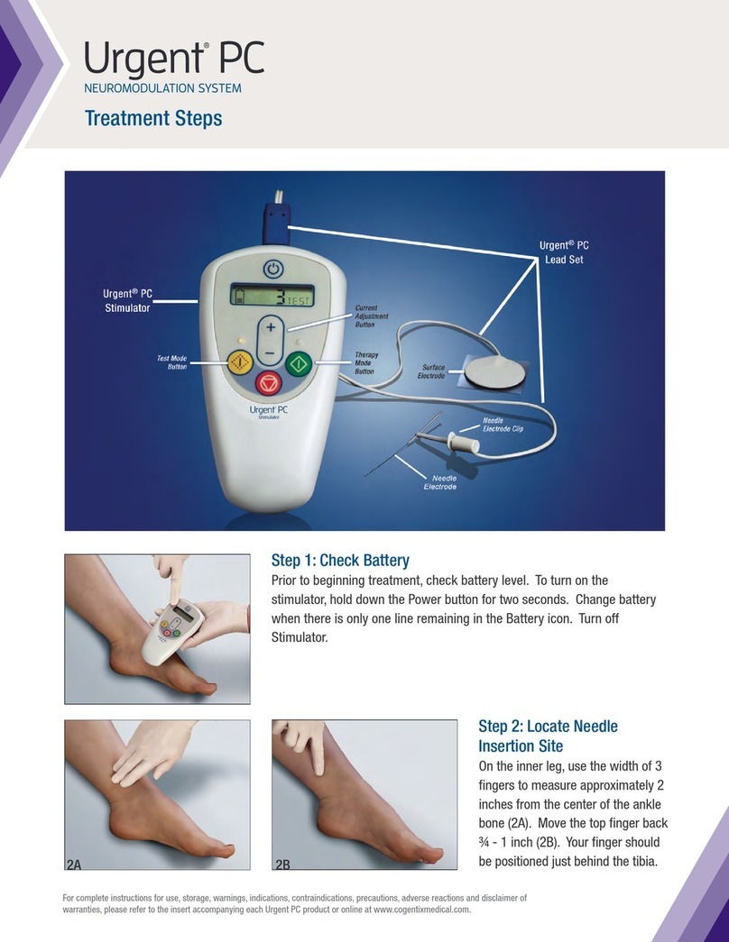
Power
Current
Adjustment
button
Test
button
Stop
button
Therapy
button
Status
Screen
CONTENTS:
Description of Symbols........................................................................ 4
Indications for Use............................................................................... 4
Product Description ............................................................................. 5
Contraindications for Use .................................................................... 5
Warnings.............................................................................................. 6
Precautions.......................................................................................... 7
Product Specications......................................................................... 8
Instructions for Use............................................................................ 12
Electromagnetic Compatibility ........................................................... 17
Warranty............................................................................................ 20

English
45
DESCRIPTION OF SYMBOLS
Prescription Use Only
Product Reference Number
Serial Number
Lot Number
Consult Instructions for Use
Temperature limitation of -20°C (-4°F) to 60°C (140°F)
Relative humidity of 20% to 80%, non-condensing
Atmospheric pressure of 500 hPa to 1060 hPa
Type BF Applied Part
Waste electrical and electronic equipment (WEEE)
should not be disposed as unsorted municipal waste;
WEEE should be collected separately.
Direct Current
9V Alkaline Battery
Classified by Underwriters Laboratories Medical
Equipment With Respect to Electric Shock, Fire, and
Mechanical Hazards Only. In accordance with UL 60601-1,
CAN/CSA C22.2 No. 601.1, EN 60601-1, IEC 60601-1,
and IEC 60601-2-10.
Manufacturer
Authorized Representative in European Community
INDICATIONS FOR USE
The Urgent®PC Neuromodulation System is intended to treat patients
suffering from urinary urgency, urinary frequency, and urge incontinence.
The Urgent PC is also indicated for the treatment of fecal incontinence.
PRODUCT DESCRIPTION
The Urgent PC Neuromodulation System is a minimally invasive
neuromodulation system designed to deliver retrograde access to the
sacral nerve through percutaneous electrical stimulation of the tibial
nerve. The method of treatment is referred to as Percutaneous Tibial
Nerve Stimulation (PTNS).
The Urgent PC Neuromodulation System is a combination of the Urgent
PC Stimulator (Stimulator) and the Urgent PC Lead Set (Lead Set). The
Stimulator and Lead Set are sold separately.
The Stimulator is a battery powered, external pulse generator and
is designed, constructed, and manufactured for multiple use. The
Stimulator is to be used only in conjunction with the single-use Lead
Set. The Lead Set (comprised of the Lead Wire, Needle Electrode,
and Alcohol Pad) transfers the electrical current from the Stimulator to
the tibial nerve via the Needle Electrode. The only components of the
Urgent PC Neuromodulation System provided sterile are the Needle
Electrodes.
CONTRAINDICATIONS FOR USE
1. In order for treatment to be effective and to avoid any possible
problems or complications, the device is contraindicated for use on
patients who have the following history or conditions:
» Patients with pacemakers or implantable defibrillators
» Patients prone to excessive bleeding
» Patients with nerve damage that could impact either
percutaneous tibial nerve or pelvic floor function
2. The Stimulator is not intended for intra-cardiac or trans-thoracic use.
3. Do not use the Stimulator on patients who are pregnant or planning
to become pregnant while using this product.
4. Concurrent use of medical monitoring equipment during stimulation
is not recommended.
5. This device is not suitable for use in the presence of a ammable
anesthetic mixture with air or with oxygen or nitrous oxide.
SN
-20°C
60°C
20%
80%
500
hPa
1060
hPa

English
67
WARNINGS
1. This Instructions for Use is NOT a comprehensive reference to
therapeutic techniques for the treatment indications noted for the
Urgent PC.
2. Users should be familiar with appropriate application and techniques
involved in the use of the Stimulator and the Lead Set.
3. Do not use the Stimulator in or around water.
4. Do not use the Stimulator or Lead Set if the skin in the area of use
is inamed, infected, or otherwise compromised. Monitor patients
during treatment for pain or skin irritation/inammation. Discontinue
use of the Stimulator if the patient complains about these symptoms
or any other discomfort.
5. Do not open battery cover while Stimulator is powered on or
connected to the patient.
6. Patients should not spend more than 30 minutes in Therapy mode
during a single treatment session.
7. The patient should remain comfortably seated, or in a supine
position, for the duration of the treatment. The patient should not rise
or walk until the treatment is complete, as mobility during treatment
has not been assessed.
8. Do not use any Lead Set component (Lead Wire, Needle Electrode
or Alcohol Pad) if the component is damaged.
9. Do not use the Needle Electrode or the Alcohol Pad if the packaging
for either component has been opened or damaged.
10. Do not reuse the single-use Needle Electrode, Surface Electrode, or
Lead Wire.
11. Dispose of used Lead Set components in a bio-hazardous material
disposal container.
12. Remove battery if equipment is not likely to be used for some time.
13. Simultaneous connection of a patient to high frequency surgical
equipment may result in burns at the site of the Stimulator electrodes
and possible damage to the Stimulator.
14. Device operation in close proximity (e.g., 1 meter) to short wave
or microwave therapy equipment may produce instability in the
Stimulator output.
15. The application of the electrodes near the thorax may increase the
risk of cardiac brillation.
16. Do not apply stimulation across or through the head, directly on the
eyes, covering the mouth, on the front of the neck (especially the
carotid sinus), chest, upper back or crossing over the heart.
17. The Stimulator has electric shock protection, Type “Internally
Powered Equipment.”
18. The Stimulator enclosure is type IPX0 and does not protect against
the ingress of water.
19. Unauthorized modication of this equipment may cause injury to
either the patient or the device operator.
PRECAUTIONS
1. Prior to using the Urgent®PC Neuromodulation System, read and
understand all instructions in the Urgent PC Stimulator Instructions for
Use and Urgent PC Lead Set Instructions for Use.
2. Caution should be used for patients with suspected or diagnosed
heart problems, especially those relating to the pacing or electrical
functioning of the heart.
3. The following are potential health risks associated with this type of
device and therapy:
» Discomfort and pain (including throbbing pain) at, or near, the
stimulation site, including the patient’s lower leg and foot
» Bleeding at the needle site
» Redness/inflammation at, or near, the stimulation site
» Potential for peripheral nerve damage
» Numbness of toes
» Stomach ache
4. Medical electrical equipment needs special precautions regarding
electromagnetic compatibility (EMC) and needs to be installed
and placed into service according to EMC guidelines provided
(see page 18 for more information).
a. Portable and mobile radio frequency (RF) communications
equipment can affect medical electrical equipment.
b. The end user of this product should assure it is used in an
appropriate environment.
i. Portable and mobile RF Communications equipment
(i.e., cell phones) should not be used at close distances.
ii. Power frequency magnetic elds should be at levels
characteristic of a typical commercial, hospital or clinic
environment.

English
89
PRODUCT SPECIFICATIONS
Urgent PC Stimulator
1. Design Features:
» Lightweight, ergonomic, handheld design
» Electronic touch pad controls
» Raised and embossed buttons to provide tactile feedback
» LCD status screen to provide operational status
» One-way fit connection site for Lead Set
2. Electrical Current Settings:
» Pulse characteristics:
◦Fixed pulse frequency of 20 Hz
◦Pulse width of 200 µseconds
◦Square waveform
» Resistance of 500-4000 Ohms.
Current
Setting
Current
(in mA)
0 0
1 0.15
2 0.5
3 1.0
4 1.5
5 2.0
6 2.5
7 3.0
8 3.5
9 4.0
Current
Setting
Current
(in mA)
10 4.5
11 5.0
12 5.5
13 6.0
14 6.5
15 7.0
16 7.5
17 8.0
18 8.5
19 9.0
Button Controls
The Stimulator is controlled by raised buttons on the device. These
buttons are:
Power button – turns power on and off
Note: To turn the power on or off, the user is required to depress
the Power button for approximately 2 seconds. This is designed
to protect the Stimulator from inadvertent status changes.
Test (yellow) button – begins Test mode
Upon entering Test mode, the default current setting will be 0
(0mA). At the completion of the Test mode, the nal current
setting shall be the baseline setting in Therapy mode.
Note: To activate Test mode, the user is required to depress the
Test mode button for approximately 2 seconds. This is designed
to protect the Stimulator from inadvertent status changes.
Therapy (green) button – begins Therapy mode
The default current setting for Therapy mode will be the nal
current setting in Test mode. However, the Current Adjustment
button may be used to increase or decrease the current level at
any time.
Note: To activate Therapy mode, the user is required to depress
the Therapy mode button for approximately 2 seconds. This is
designed to protect the Stimulator from inadvertent status changes.
Stop (red) button – stops ow of current in Test or Therapy
mode
Note: If treatment is stopped or interrupted during Therapy mode,
the remaining Therapy mode time is displayed. Once stopped,
the treatment session will need to be restarted, beginning with
Test mode. Depending on when the session was interrupted, a
new Lead Set may be required.
Current Adjustment button – increases or decreases current
Note: The current is adjustable in both Test and Therapy modes.
Note: if the Stimulator is not in Test or Therapy mode and no button is
pressed for 15 minutes, the Stimulator will power down.

English
10 11
Status Screen
Icons and alpha-numeric characters on the Status Screen provide
operational feedback. These include:
Battery Level icon
The number of horizontal lines displayed in the Battery Level
icon represents the remaining battery life. Seven horizontal
lines indicate a fully charged battery whereas one horizontal line
indicates that the battery is nearly empty. A ashing Battery Level
icon signals that a replacement battery is needed. In addition, the
Stimulator will emit a beep every 15 seconds when the battery is
nearly empty (only one line displayed in the Battery Level icon).
Note: The system is designed to prohibit the start of Test mode
if there is insufcient battery life remaining to complete the
treatment.
Lead Wire Status icon
Indicates the functional status of the Lead Wire. The icon will ash
if a new Lead Wire is required.
Inactive Current icon
Indicates that current is not owing through the Lead Set. Check
the security of the Lead Connector, the adherence of the Surface
Electrode, and the placement of the Needle Electrode Clip.
Active Current icon
Indicates that current is actively owing through the Lead Set.
Service Required icon
If a fault is detected, Therapy mode will end and the Service
Required icon will appear on the screen. Contact Cogentix Medical
for further instructions.
Note: Holding down more than one button at start-up may result
in the Service Required icon appearing on the display. If this icon
appears at start-up, use the Power button to turn the device off
and on.
Treatment Status (Lower right of screen)
During Test Mode, the word “TEST” will appear on the screen.
Once Therapy mode is started, a countdown timer will appear in
the lower right of the display. This timer indicates how much time
is left in the 30 minute Therapy session.
Upon completion of Therapy, the word “END” will ash on the
screen until shutdown.
Current Setting (Center of screen)
The selected current setting is displayed at all times in the center
of the status screen. The current is adjustable in both Test and
Therapy modes.
Urgent PC Lead Set
The Lead Set transfers the electrical current from the Stimulator to the
tibial nerve and includes:
» Lead Wire: the components of the Lead Wire create the non-sterile
circuit interface between the Simulator and the patient. A one-way
t Stimulator connector is attached to the proximal end of the Lead
Wire. The distal end of the Lead Wire is split into individual wires.
One wire is attached to an adhesive-backed Surface Electrode; the
other is attached to the Needle Electrode Clip.
» Needle Electrodes: two 34 Ga. solid stainless steel Needle
Electrodes, each contained within a plastic guide tube with stop plug.
Each Needle Electrode is supplied sterile in an individual peel-open
package.
» Alcohol Pad: a prepackaged alcohol pad to clean the Needle
Electrode insertion site.

English
12 13
2. Insert the Needle Electrode
» Locate the insertion site for the Needle
Electrode by identifying the location on
the lower inner aspect of either leg that
is approximately three fingerbreadths
(5 cm or 2”) cephalad to the medial
malleolus and approximately one
fingerbreadth (2 cm or ¾”) posterior to
the tibia.
» To prepare the Needle Electrode insertion site, open the Lead
Set packaging. Remove and open the Alcohol Pad. Use the
Alcohol Pad to clean the skin area surrounding the identified
insertion site.
» Place the patient in a comfortable position, supine or sitting, for
easy access to the insertion site; for example, the patient may
sit with the soles of the feet together and knees abducted and
flexed. Open the sterile Needle Electrode package and remove
the Needle Electrode/guide tube assembly.
» Place the Needle Electrode/guide tube assembly over the
identified and cleaned insertion site in a position that creates a
60-degree angle between the Needle Electrode and the ankle.
Remove the stop plug in the guide tube to release the Needle
Electrode.
» Gently tap the Needle Electrode head to pierce the skin. Once
the Needle Electrode has penetrated the skin, remove the guide
tube and advance the Needle Electrode
using a rotating motion to facilitate entry.
Note: it is important to maintain a 60-degree
angle with the Needle Electrode while
advancing it in a path that is parallel to the
tibia. When appropriately inserted,
approximately 2 cm (¾”) of the Needle
Electrode will be inserted in the leg.
INSTRUCTIONS FOR USE
This therapy, percutaneous tibial nerve stimulation (PTNS), involves
placing the Needle Electrode into the lower, inner aspect of either leg
slightly cephalad to the medial malleolus. A Surface Electrode is placed
over the medial aspect of the calcaneous on the same leg. The Lead
Wire is rst connected to the Stimulator, and then the Needle Electrode
Clip is connected to the Needle Electrode. The Stimulator produces an
adjustable electrical pulse that travels to the sacral nerve plexus via the
tibial nerve. Among other functions, the sacral nerve plexus regulates
bladder and pelvic oor function.
The patient is typically treated once per week for 30 minutes for a period
of 12 weeks. No decision to discontinue treatment should be made until
the patient completes the 12 treatments. For patients responding to
treatment, the time between treatment sessions may be slowly increased
after the initial 12 treatments, with the patient closely monitored for the
return of symptoms. If symptoms reappear or increase in severity, the
patient’s treatment schedule should revert to the last previously effective
treatment schedule.
TREATMENT PROTOCOL FOR EACH TREATMENT SESSION
1. Check Battery Level
» Before beginning any treatment session, it is advisable to
check the battery level. To check the battery level, turn on
the Stimulator by pressing and holding the Power Button for
approximately 2 seconds. An audible tone will sound and icons
will appear on the screen. Battery replacement is recommended
when there is only one line remaining in the Battery Level icon.
To conserve battery power, the Stimulator may be turned off
during patient preparation.
Note: The system is designed to prohibit the start of Test mode
if there is insufficient battery life remaining to complete the
treatment.

English
14 15
» Using the Current Adjustment button, slowly increase the current
while monitoring the patient for a response. Patient response
may be either motor or sensory. For some patients it is both.
Motor response is typically a toe flex or fan, or an extension of
the entire foot. Sensory response is generally described as a
tingling sensation that travels away from the insertion site,
towards the heel, arch or toes.
» Once a patient response is confirmed, reduce current setting by
one level and begin Therapy mode.
» If the incremental adjustment of amplitude fails to elicit either
a motor or a sensory response, press the Stop button and
reposition the Needle Electrode slightly. Re-enter Test mode
using the preceding instructions.
» If repositioning the Needle Electrode and repeating the current
step-up procedure fails to elicit patient response, discard the
Needle Electrode. Open the second Needle Electrode included
in the Lead Set and repeat the procedure on the other leg.
7. Conduct Therapy
» After completing Test mode, Therapy mode can be entered by
either:
1) Pressing the Stop button to end Test mode and then
pressing the Therapy button to start Therapy mode.
or 2) Pressing the Therapy button while the Test mode is still
active.
Note: Test mode is a prerequisite to Therapy mode.
» To ensure optimal treatment, the default current setting for
Therapy mode will be the final current setting in Test mode.
However, the Current Adjustment button can be used to
increase or decrease the current level at any time during
Therapy mode.
3. Connect Lead Wire to the Stimulator
» Plug the one-way fit connector of the
Lead Wire into the Stimulator’s
connection site. Verify that the one-way
fit connector is inserted correctly.
4. Attach the Surface Electrode
» Remove the adhesive backing from the Surface Electrode.
» Place the Surface Electrode near the medial aspect of the
calcaneus on the same leg as the Needle Electrode insertion.
5. Attach Needle Electrode Clip
» Depress the plunger on the Needle
Electrode Clip to expose the connection
hook at the tip. Loop the connection
hook around the Needle Electrode and
release.
6. Determine Current Setting for Therapy
» Turn on the Stimulator by pressing and holding the Power button
for approximately 2 seconds. An audible tone will sound and
symbols will appear on the screen.
Note: If the Lead Wire Status icon is blinking, ensure that the
Lead Wire connector is secure in the Stimulator’s connection site.
» Enter Test mode by pressing and holding the Test button for
approximately 2 seconds. The default setting for Test mode is
level 0 (0mA current).
Note: If the Inactive Current icon appears, current is not flowing
through the Lead Set. Check the security of the Lead Wire
connector, the adherence of the Surface Electrode, and the
placement of the Needle Electrode Clip.

English
16 17
» Therapy mode time is automatically set for 30 minutes.
» When the therapy time has elapsed, Therapy mode will
automatically end, the current will be inactive, and the Stimulator
will emit a series of three beeps.
8. Complete Treatment Session
» Turn off the Stimulator by holding down the Power button for
approximately 2 seconds.
» Remove the Needle Electrode Clip from the Needle Electrode.
» Using a smooth, fluid motion, quickly remove the Needle
Electrode from the leg. If bleeding occurs, apply slight pressure
and bandage.
» Disconnect the Lead Wire from the Stimulator and properly
dispose of Lead Set components.
» The treatment session is now complete.
TREATMENT FREQUENCY
» Conduct 12 treatments, typically once per week.
» After the initial 12 treatments, slowly increase the time between
treatments, with the patient closely monitored for the return of
symptoms.
» If symptoms reappear or increase in severity, the patient’s treatment
schedule should revert to the last previously effective treatment
schedule.
MAINTENANCE
After each treatment the surface of the Stimulator device should be
wiped down with a soft cloth. The cloth may be slightly dampened, but
not saturated, with water or with a mix of isopropyl alcohol (70%) and
water (30%).
Use only a 9V alkaline battery (e.g., Duracell) to power the Stimulator.
Never operate the Stimulator with any type of line-powered battery
eliminator or other external power source. Battery life is dependent on
the intensity of treatment; a new 9V battery will perform approximately
12 treatments at a current setting of 5mA (level 11). Recycle or
dispose of batteries in compliance with applicable local and/or national
regulations. If the Stimulator is not working properly, contact Cogentix
Medical.
PERMISSIBLE OPERATING ENVIRONMENT
» Ambient temperature 10°C to 40°C
» Relative humidity 30% to 75%
» Atmospheric pressure 700 hPa to 1060 hPa
MANUFACTURING
The Stimulator is manufactured in accordance with the safety norms set
forth by the International Electrotechnical Commission and Underwriters
Laboratory, IEC/UL 60601, including electromagnetic compatibility.
ELECTROMAGNETIC COMPATIBILITY
Guidance and Manufacturer’s Declaration – Electromagnetic Emissions
The Urgent PC Stimulator is intended for use in the electromagnetic environment
specied below. The customer or the user of the Urgent PC Stimulator should assure
that it is used in such an environment.
Emissions Test Compliance Electromagnetic Environment – Guidance
RF emissions
CISPR 11
Group 1 The Urgent PC Stimulator uses RF energy
only for its internal function. Therefore, its RF
emissions are very low and are not likely to
cause any interference in nearby electronic
equipment.
RF emissions
CISPR 11
Class B The Urgent PC Stimulator is suitable for use
in all establishments other than domestic and
those directly connected to the public low-
voltage power supply network that supplies
buildings for domestic purposes.
Harmonic
emissions
IEC 61000-3-2
Not applicable
Voltage
uctuations/
icker emissions
IEC 61000-3-3
Not applicable

English
18 19
Guidance and Manufacturer’s Declaration – Electromagnetic Immunity
The Urgent PC Stimulator is intended for use in the electromagnetic environment
specied below. The customer or the user of the Urgent PC Stimulator should assure
that it is used in such an environment.
Immunity Test IEC 60601 Test
Level
Compliance
Level
Electromagnetic
Environment –
Guidance
Electrostatic
discharge (ESD)
IEC 61000-4-2
± 6kV contact
± 8kV air
± 6 kV
contact
± 8 kV air
Floors should be wood,
concrete or ceramic tile.
If oors are covered with
synthetic material, the
relative humidity should
be at least 30%.
Electrical fast
transient/burst
IEC 61000-4-4
± 2kV for power
supply lines
± 1kV for input/
output lines
Not
applicable
Not applicable
Surge
IEC 61000-4-5
± 1kV differential
mode
±2 kV common
mode
Not
applicable
Not applicable
Voltage
dips, short
interruptions
and voltage
variations on
power supply
input lines
IEC 61000-4-11
<5 % UT
(>95 % dip in UT)
for 0,5 cycle
40 % UT
(>95 % dip in UT)
for 5 cycles
70 % UT
(>95 % dip in UT)
for 25 cycles
<5 % UT
(>95 % dip in UT)
for 5 sec
Not
applicable
Not applicable
Power
frequency
(50/60 Hz)
magnetic eld
IEC 61000-4-8
3 A/m Not
applicable
Not applicable
Guidance and Manufacturer’s Declaration – Electromagnetic Immunity
The Urgent PC Stimulator is intended for use in the electromagnetic environment
specied below. The customer or the user of the Urgent PC Stimulator should assure
that it is used in such an environment.
Immunity
Test IEC 60601
Test Level Compliance
Level
Electromagnetic Environment – Guidance
Conducted
RFIEC
61000-4-6
Radiated
RFIEC
61000-4-3
3 Vrms
150 kHz to
80 MHz
3 V/m
80MHz to
2,5 GHz
3 Vrms
3 V/m
Portable and mobile RF communications
equipment should be used no closer to any part of
the Urgent PC Stimulator, including cables, than
the recommended separation distance calculated
from the equation applicable to the frequency of
the transmitter.
Recommended separation distance
d = 1,2√P
d = 1,2√P80 MHz to 800 MHz
d = 2,3√P800 MHz to 2,5 GHz
where Pis the maximum output power rating
of the transmitter in watts (W) according to
the transmitter manufacturer and dis the
recommended separation distance in metres (m).
Field strength from xed RF transmitters, as
determined by an electromagnetic site survey,a
should be less than the compliance level in each
frequency range.b
Interference may occur in the vicinity of equipment
marked with the following symbol:
NOTE 1 At 80 MHz and 800 MHz, the higher frequency range applies.
NOTE 2 These guidelines may not apply in all situations. Electromagnetic propagation is
affected by absorption and reection from structures, objects and people.
a Field strengths from xed transmitters, such as base stations for radio (cellular/
cordless) telephones and land mobile radios, amateur radio, AM and FM radio broadcast
and TV broadcast cannot be predicted theoretically with accuracy. To assess the
electromagnetic environment due to xed RF transmitters, an electromagnetic site survey
should be considered. If the measured eld strength in the location in which the Urgent
PC Stimulator is used exceeds the applicable RF compliance level above, the Urgent PC
Stimulator should be observed to verify normal operation. If abnormal performance is
observed, additional measures may be necessary, such as re-orienting or relocating the
Urgent PC Stimulator
b Over the frequency range 150 kHz to 80 MHz, eld strengths should be less than 3 V/m.

English
20 21
Recommended Separation Distances Between Portable and Mobile RF
Communications Equipment and the Urgent PC Stimulator
The Urgent PC is intended for use in an electromagnetic environment in which radiated
RF disturbances are controlled. The customer or the user of the Urgent PC Stimulator
can help prevent electromagnetic interference by maintaining a minimum distance
between portable and mobile RF communications equipment (transmitters) and the
Urgent PC Stimulator as recommended below, according to the maximum output
power of the communications equipment.
Rated Maximum
Output Power of
Transmitter
W
Separation Distance According to Frequency of
Transmitter
m
150 kHz to 80
MHz
d = 1,2√P
80 MHz to 800 MHz
d = 1,2√P
800 MHz to 2,5
GHz
d = 2,3√P
0,01 0,12 0,12 0,23
0,1 0,38 0,38 0,73
1 1,2 1,2 2,3
10 3,8 3,8 7,3
100 12 12 23
For transmitters rated at a maximum output power not listed above, the recommended
separation distance din metres (m) can be estimated using the equation applicable to
the frequency of the transmitter, where P is the maximum output power rating of the
transmitter in watts (W) according to the transmitter manufacturer.
NOTE 1 At 80 MHz and 800 MHz, the separation distance for the higher frequency
range applies.
NOTE 2 These guidelines may not apply in all situations. Electromagnetic propagation
is affected by absorption and reection from structure, objects and people.
WARRANTY
Cogentix Medical warrants that reasonable care has been used to
design and manufacture this product. Product will be replaced if
Cogentix Medical determines its material or workmanship is defective.
This is Cogentix Medical’s only warranty, and it excludes all other
warranties (including those implied by operation of law). Cogentix
Medical is not responsible for matters within the control of the user or
others, such as product handling and storage, patient selection and
diagnosis, and treatment procedures.
This Limited Warranty is limited to its express terms. In particular:
(1) Except as expressly provided by this Limited Warranty, COGENTIX
MEDICAL IS NOT RESPONSIBLE FOR ANY DIRECT, INCIDENTAL OR
CONSEQUENTIAL DAMAGES BASED ON ANY DEFECT, FAILURE
OR MALFUNCTION OF THE PRODUCT, WHETHER THE CLAIM IS
BASED ON WARRANTY, CONTRACT, TORT OR OTHERWISE.
(2) This Limited Warranty is made only to the purchaser of the Product.
AS TO ALL OTHERS, COGENTIX MEDICAL MAKES NO WARRANTY,
EXPRESS OR IMPLIED, INCLUDING, BUT NOT LIMITED TO, ANY
IMPLIED WARRANTY OF MERCHANTABILITY OR FITNESS FOR
A PARTICULAR PURPOSE WHETHER ARISING FROM STATUTE,
COMMON LAW, CUSTOM OR OTHERWISE. THIS LIMITED
WARRANTY SHALL BE THE EXCLUSIVE REMEDY AVAILABLE TO
ANY PERSON.
Any implied warranties of merchantability or tness are specically
excluded. Statements and descriptions in marketing literature, while
generally describing this product, do not constitute any warranties.
DISCLAIMER OF WARRANTIES
Cogentix Medical excludes all warranties and responsibilities for:
» Improper use of or tampering with the product
» Failure to follow instructions provided in this insert, and/or
» Failure to follow the Instructions for Use for Urgent PC Stimulator and
Urgent PC Lead Set.

Deutsch
22 23
Netzschalter
Stromeinstellungstaste
Testtaste
Stopptaste
Statusanzeige
INHALT:
Beschreibung der Symbole ............................................................... 23
Indikationen....................................................................................... 23
Produktbeschreibung......................................................................... 24
Kontraindikationen............................................................................. 24
Warnhinweise.................................................................................... 25
Vorsichtsmaßnahmen........................................................................ 26
Produktspezikationen ...................................................................... 27
Gebrauchsanweisung........................................................................ 32
Elektromagnetische Verträglichkeit ................................................... 38
Gewährleistung.................................................................................. 43
Behandlungs-
taste
BESCHREIBUNG DER SYMBOLE
Verschreibungspflichtig
Artikelnummer
Seriennummer
Chargenbezeichnung
Gebrauchsanweisung beachten
Temperaturgrenzwerte: -20 °C (-4 °F) bis 60 °C (140 °F)
Relative Luftfeuchtigkeit 20 % bis 80 %, nicht-
kondensierend
Atmosphärischer Druck von 500 hPa bis 1060 hPa
Anwendungsteil vom Typ BF
Elektro- und Elektronik-Altgeräte (WEEE) dürfen nicht
als unsortierter städtischer Restmüll entsorgt werden.
Elektro- und Elektronik-Altgeräte müssen getrennt
gesammelt werden.
Gleichstrom
9-Volt-Alkalibatterie
Medizinprodukt geprüft durch Underwriters Laboratories
nur in Bezug auf elektrischen Schlag, Feuer und
mechanische Gefährdung. In Übereinstimmung mit
UL 60601-1, CAN/CSA C22.2 Nr. 601.1, EN 60601-1,
IEC 60601-1 und IEC 60601-2-10.
Hersteller
Bevollmächtigter in der Europäischen Union
INDIKATIONEN
Das Urgent®PC-Neuromodulationssystem ist für die Behandlung von
Patienten vorgesehen, die unter Harndrang, erhöhter Miktionsfrequenz und
SN
-20°C
60°C
20%
80%
500
hPa
1060
hPa

Deutsch
24 25
Dranginkontinenz leiden. Das Urgent PC-System ist außerdem für die
Behandlung von Darminkontinenz indiziert.
PRODUKTBESCHREIBUNG
Das Urgent PC-Neuromodulationssystem ist ein minimalinvasives
Neuromodulationssystem, das zur Schaffung eines retrograden Zugangs
zu den Sakralnerven durch perkutane elektrische Stimulation des
Nervus tibialis vorgesehen ist. Dieses Behandlungsverfahren wird als
perkutane Stimulation des Nervus tibialis (PTNS) bezeichnet.
Das Urgent PC-Neuromodulationssystem besteht aus dem Urgent
PC-Stimulator (Stimulator) und dem Urgent PC-Draht-Set (Draht-Set).
Stimulator und Draht-Set sind separat erhältlich.
Der Stimulator ist ein batteriebetriebener, externer Impulsgenerator und
für die Mehrfachverwendung konzipiert, gebaut und hergestellt. Er ist
nur in Kombination mit dem für den einmaligen Gebrauch bestimmten
Draht-Set zu verwenden. Das Draht-Set (bestehend aus Leitungsdraht,
Nadelelektrode und Alkoholkompresse) überträgt den elektrischen Strom
über die Nadelelektrode vom Stimulator zum Nervus tibialis. Die einzigen
steril gelieferten Komponenten des Urgent PC-Neuromodulationssystems
sind die Nadelelektroden.
KONTRAINDIKATIONEN
1. Für eine effektive Behandlung und um mögliche Probleme oder
Komplikationen zu vermeiden, ist dieses Medizinprodukt für die
Anwendung bei Patienten mit der folgenden Anamnese bzw. den
folgenden Beschwerden kontraindiziert:
» Patienten mit Schrittmachern oder implantierbaren Defibrillatoren
» Patienten mit übermäßiger Blutungsneigung
» Patienten mit Nervenschädigung, die die perkutane N. tibialis-
oder Beckenbodenfunktion beeinträchtigen könnte.
2. Der Stimulator ist nicht für die intrakardiale oder transthorakale
Anwendung vorgesehen.
3. Der Stimulator darf nicht bei schwangeren Patientinnen angewendet
oder Patientinnen, die während der Anwendung dieses Produktes
eine Schwangerschaft planen.
4. Die gleichzeitige Anwendung medizinischer Überwachungsgeräte
während der Stimulation wird nicht empfohlen.
5. Dieses Medizinprodukt darf nicht in Gegenwart leicht entzündlicher
Anästhetikamischungen aus Luft, Sauerstoff oder Stickstoffoxid
verwendet werden.
WARNHINWEISE
1. Diese Gebrauchsanweisung stellt KEINE umfassende Referenz
für therapeutische Techniken zur Behandlung der für das Urgent
PC-System angegebenen Indikationen dar.
2. Der Benutzer sollte mit den entsprechenden Anwendungen und
Techniken vertraut sein, die mit dem Einsatz von Stimulator und
Draht-Set verbunden sind.
3. Den Stimulator nicht in oder in der Nähe von Wasser anwenden.
4. Stimulator und Draht-Set dürfen nicht angewendet werden, wenn
die Haut des zu behandelnden Bereichs entzündet, inziert oder auf
sonstige Weise beeinträchtigt ist. Patienten während der Anwendung
auf Schmerzen oder Hautreizungen bzw. -entzündungen beobachten.
Den Einsatz des Stimulators abbrechen, wenn der Patient über diese
Symptome oder sonstige Beschwerden klagt.
5. Batterieabdeckung nicht öffnen, wenn der Stimulator eingeschaltet
oder an den Patienten angeschlossen ist.
6. Die Anwendung des Behandlungsmodus sollte während einer
Behandlungssitzung 30 Minuten nicht überschreiten.
7. Während der Behandlung sollte der Patient bequem sitzen oder in
Rückenlage gelagert sein. Der Patient darf während der Behandlung
nicht aufstehen und umher laufen, da keine Erkenntnisse über die
Auswirkungen von Bewegung während der Behandlung vorliegen.
8. Beschädigte Komponenten des Draht-Sets (Leitungsdraht,
Nadelelektrode oder Alkoholkompresse) nicht verwenden.
9. Die Nadelelektrode bzw. die Alkoholkompresse nicht verwenden,
falls die Verpackung einer dieser Komponenten geöffnet wurde oder
beschädigt ist.
10. Die Einweg-Nadelelektroden, Oberächenelektroden und
Leitungsdrähte nicht wiederverwenden.
11. Die Komponenten des Draht-Sets in einem Abfallbehälter für
biologisch gefährliche Materialien entsorgen.
12. Die Batterie herausnehmen, wenn das Gerät voraussichtlich längere
Zeit nicht verwendet wird.

Deutsch
26 27
13. Der gleichzeitige Anschluss von chirurgischen Hochfrequenzsystemen
am Patienten kann zu Verbrennungen an den Positionen der
Stimulatorelektroden sowie zu möglichen Beschädigungen des
Stimulators führen.
14. Der Betrieb des Gerätes in unmittelbarer Nähe (d. h. im Umkreis von
1 Meter) von Kurzwellen- oder Mikrowellen-Therapiegeräten kann
eine instabile Leistung des Stimulators zur Folge haben.
15. Die Anwendung der Elektroden in Thoraxnähe kann das Risiko von
Herzimmern erhöhen.
16. Keine Stimulation im Kopfbereich, direkt auf den Augen, im
Mundbereich, im vorderen Halsbereich (insbesondere an der
Halsschlagader), im Brustbereich, am oberen Rücken oder quer über
dem Herzbereich durchführen.
17. Der Stimulator ist mit einer Schutzvorrichtung gegen Stromschläge
ausgestattet, Schutzart „Gerät mit interner Stromversorgung“.
18. IP-Schutzgrad des Gehäuses: IPX0, kein Schutz vor eindringendem
Wasser.
19. Eine unsachgemäße Veränderung an diesem Gerät kann zu
Verletzungen des Patienten oder des Gerätebedieners führen.
VORSICHTSMASSNAHMEN
1. Vor der Anwendung des Urgent®PC-Neuromodulationssystems alle
Anweisungen in der Gebrauchsanweisung des Urgent PC-Stimulators
und in der Gebrauchsanweisung des Urgent Draht-Sets für die
PC-Stimulation sorgfältig durchlesen.
2. Vorsicht bei Patienten mit Verdacht auf oder mit bestätigten
Herzproblemen, insbesondere im Zusammenhang mit der Stimulation
oder der elektrischen Funktion des Herzens.
3. Die folgenden potentiellen Gesundheitsrisiken sind mit diesem
Gerätetyp und dieser Behandlung verbunden:
» Unwohlsein und Schmerzen (einschließlich klopfender
Schmerzen) an oder im Bereich der Stimulationsstelle
einschließlich des Unterschenkels und Fußes des Patienten
» Blutung an der Einstichstelle der Nadel
» Rötung/Entzündung an oder im Bereich der Stimulationsstelle
» Taubheitsgefühl in den Zehen
» Magenschmerzen
4. Medizinische elektrische Geräte bedürfen besonderer
Vorsichtsmaßnahmen in Bezug auf die elektromagnetische
Verträglichkeit (EMV) und müssen gemäß den EMV-Leitlinien in
dieser Gebrauchsanweisung installiert und in Betrieb genommen
werden (siehe Seite 40 für weitere Informationen).
a. Tragbare und mobile Hochfrequenz (HF)-Kommunikationsgeräte
können die Leistung dieser elektrischen medizinischen
Ausrüstung beeinträchtigen.
b. Der Endanwender dieses Produktes hat sicherzustellen, dass
es in einer geeigneten Umgebung betrieben wird.
i. Keine tragbaren und mobilen HF-Kommunikationsgeräte
(d. h. Mobiltelefone) in unmittelbarer Nähe in Betrieb
nehmen.
ii. Die Magnetfelder mit Netzfrequenzen müssen den für eine
gewerbliche oder Klinikumgebung typischen Bereichen
entsprechen.
PRODUKTSPEZIFIKATIONEN
Urgent PC-Stimulator
1. Designmerkmale:
» Leichtgewichtiges, ergonomisches, handliches Design
» Elektronische Touchpad-Bedienelemente
» Hervorstehende und geprägte Tasten für taktiles Feedback
» LCD-Anzeige zeigt Betriebsstatusan
» Einseitig gerichteter Steckverbinder für das Draht-Set

Deutsch
28 29
2. Einstellungen der elektrischen Stromstärke:
» Impulscharakteristik:
◦Feste Impulsfrequenz von 20 Hz
◦ Impulsdauer 200 μs
◦Rechteckwellenform
» Widerstand 500–4,000 Ohm
Einstellungen
der elektrischen
Stromstärke
Stromstärke
(in mA)
0 0
1 0,15
2 0,5
3 1,0
4 1,5
5 2,0
6 2,5
7 3,0
8 3,5
9 4,0
Einstellungen
der elektrischen
Stromstärke
Stromstärke
(in mA)
10 4,5
11 5,0
12 5,5
13 6,0
14 6,5
15 7,0
16 7,5
17 8,0
18 8,5
19 9,0
Tastenfunktionen
Die Steuerung des Stimulators erfolgt über hervorstehende Tasten am
Gerät. Folgende Tasten stehen zur Verfügung:
Netzschalter - Ein- und Ausschalten
Hinweis: Um das Gerät ein- bzw. auszuschalten, muss der
Anwender den Netzschalter ca. 2 Sekunden gedrückt halten.
Auf diese Weise wird ein versehentlicher Statuswechsel des
Stimulators verhindert.
Testtaste (gelb) – Starten des Testmodus
Die anfängliche Standardeinstellung der Stromstärke
im Testmodus ist Stufe 0 (0 mA). Nach Beendigung des
Testmodus entspricht die letzte Einstellung der Stromstärke der
Grundeinstellung im Behandlungsmodus.
Hinweis: Der Anwender aktiviert den Testmodus, indem er ca.
2 Sekunden lang die Testtaste drückt. Auf diese Weise wird ein
versehentlicher Statuswechsel des Stimulators verhindert.
Behandlungstaste (grün) – Starten des Behandlungsmodus
Die Standardeinstellung der Stromstärke im Behandlungsmodus
entspricht der letzten Einstellung der Stromstärke im
Testmodus. Die Stromstärkenstufe kann jedoch jederzeit mit der
Stromeinstellungstaste erhöht oder verringert werden.
Hinweis: Der Anwender aktiviert den Behandlungsmodus, indem er
ca. 2 Sekunden lang die Behandlungstaste drückt. Auf diese Weise
wird ein versehentlicher Statuswechsel des Stimulators verhindert.
Stopptaste (rot) – Beendigung des Stromusses im Test- oder
Behandlungsmodus
Hinweis: Wird die Behandlung im Behandlungsmodus gestoppt
bzw. unterbrochen, wird die verbleibende Behandlungsdauer
angezeigt. Wurde die Behandlung gestoppt, muss die
Behandlungssitzung mit dem Testmodus erneut gestartet
werden. Je nach Zeitpunkt der Behandlungsunterbrechung kann
ein neues Draht-Set erforderlich sein.
Stromeinstellungstaste – Erhöhung oder Verringerung der
Stromstärke
Hinweis: Die Stromstärke kann sowohl im Test- wie auch im
Behandlungsmodus eingestellt werden.
Hinweis: Wird 15 Minuten lang keine Taste betätigt, während sich der
Stimulator weder im Test- noch im Behandlungsmodus bendet, schaltet
sich der Stimulator automatisch ab.

Deutsch
30 31
Statusanzeige
Die Symbole und alphanumerischen Zeichen der Statusanzeige geben
den Betriebsstatus des Gerätes an. Die Bedeutung der Symbole ist wie
folgt:
Batteriesymbol
Die Anzahl der waagerechten Linien im Batteriesymbol gibt die
verbleibende Kapazität der Batterie an. Sieben waagerechte Linien
zeigen eine vollständig geladene Batterie an. Wird nur noch eine
waagerechte Linie angezeigt, ist die Batterie nahezu entladen.
Ein blinkendes Batteriesymbol zeigt an, dass eine Ersatzbatterie
erforderlich ist. Ist die Batterie nahezu entladen (nur noch eine
Linie im Batteriesymbol), ertönt zudem alle 15 Sekunden ein
akustisches Signal.
Hinweis: Falls die Batteriekapazität für eine vollständige
Behandlung nicht mehr ausreicht, verhindert das System den Start
des Testmodus.
Leitungsdraht-Symbol
Zeigt den Funktionsstatus des Leitungsdrahtes an. Das Symbol
blinkt, wenn ein neuer Leitungsdraht erforderlich ist.
Symbol „Kein Strom“
Zeigt an, dass kein Strom durch das Draht-Set ießt. Anschluss
der Drahtverbindung, Haftung der Oberächenelektrode und
Platzierung der Nadelelektrodenklemme prüfen.
Symbol „Strom aktiv“
Zeigt aktiven Stromuss durch das Draht-Set an.
Wartungssymbol
Bei Erfassung einer Störung wird der Behandlungsmodus beendet,
und in der Anzeige erscheint das Wartungssymbol. Wenden Sie
sich an Cogentix Medical, um weitere Anweisungen zu erhalten.
Hinweis: Das Drücken mehrerer Tasten beim Systemstart kann dazu
führen, dass das Wartungssymbol angezeigt wird. Erscheint dieses
Symbol beim Systemstart, das Gerät mit dem Netzschalter aus- und
wieder einschalten.
Behandlungsstatus (unten rechts in der Anzeige)
Im Testmodus wird das Wort „TEST“ eingeblendet.
Sobald der Behandlungsmodus gestartet wurde, erscheint unten
rechts eine rückwärts laufende Zeitanzeige. Diese Zeitanzeige gibt
die verbleibende Zeit der 30-minütigen Behandlung an.
Nach Abschluss der Behandlung blinkt das Wort „END“ (Ende) so
lange in der Anzeige, bis das System heruntergefahren wird.
Einstellung der Stromstärke (Mitte der Anzeige)
Die gewählte Einstellung der Stromstärke wird stets in der Mitte
der Statusanzeige eingeblendet. Die Stromstärke kann sowohl im
Test- wie auch im Behandlungsmodus eingestellt werden.
Urgent PC-Draht-Set
Das Draht-Set überträgt den elektrischen Strom vom Stimulator auf den
Nervus tibialis. Es umfasst folgende Komponenten:
» Leitungsdraht: Die Komponenten des Leitungsdrahtes bilden die
unsterile Schnittstellenschaltung zwischen Stimulator und Patient.
Am proximalen Ende des Leitungsdrahtes ist ein einseitig gerichteter
Steckverbinder für den Anschluss am Stimulator angebracht. Das distale
Ende des Leitungsdrahtes ist in Einzeldrähte unterteilt. Ein Draht ist an
einer mit selbstklebender Rückseite versehenen Oberächenelektrode
befestigt, der andere Draht ist an der Nadelelektrodenklemme befestigt.
» Nadelelektroden: Zwei 34-G-Nadelelektroden aus massivem
Edelstahl, die sich jeweils in einem Führungsrohr aus Kunststoff mit
Verschlussstopfen benden. Jede Nadelelektrode wird steril in einer
aufreißbaren Einzelverpackung geliefert.
» Alkoholkompresse: Eine abgepackte Alkoholkompresse zur Reinigung
der Einführstelle der Nadelelektrode.

Deutsch
32 33
GEBRAUCHSANWEISUNG
Die perkutane Stimulation des Nervus tibialis (PTNS) verlangt die
Platzierung der Nadelelektrode am distalen medialen Aspekt eines
Beins leicht kranial des Malleolus medialis. Eine Oberächenelektrode
wird oberhalb des medialen Aspekts des Kalkaneus desselben Beins
platziert. Der Leitungsdraht wird zunächst mit dem Stimulator verbunden.
Anschließend wird die Nadelelektrodenklemme mit der Nadelelektrode
verbunden. Der Stimulator erzeugt einen regelbaren elektrischen Impuls,
der über den Nervus tibialis zum Sakralnervengeecht wandert. Neben
weiteren Funktionen reguliert das Sakralnervengeecht die Funktion von
Blase und Beckenboden.
Der Patient wird in der Regel über einen Zeitraum von 12 Wochen jeweils
einmal pro Woche 30 Minuten lang behandelt. Ein Abbruch der Therapie
sollte nicht vor Abschluss der 12 Behandlungssitzungen in Betracht
gezogen werden. Bei Patienten, die auf die Behandlung ansprechen,
kann nach Abschluss der ersten 12 Sitzungen die Zeit zwischen den
Behandlungen allmählich erhöht werden, wobei der Patient engmaschig
im Hinblick auf das etwaige Wiederauftreten von Symptomen beobachtet
werden muss. Falls Symptome erneut auftreten oder an Schwere
zunehmen, sollte der letzte zuvor wirksame Behandlungsplan wieder
aufgenommen werden.
BEHANDLUNGSPROTOKOLL FÜR JEDE BEHANDLUNGSSITZUNG
1. Überprüfen des Batteriestatus
» Vor Beginn jeder Behandlung sollte der Batteriestatus überprüft
werden. Dazu den Netzschalter ca. 2 Sekunden gedrückt halten,
um den Stimulator einzuschalten. Ein akustisches Sonsignal
ertönt und in der Anzeige erscheinen Symbole. Weist das
Batteriesymbol nur noch eine Linie auf wird ein Batteriewechsel
empfohlen. Um Batterieleistung zu sparen, kann der Stimulator
während der Vorbereitung des Patienten ausgeschaltet werden.
Hinweis: Reicht die Batteriekapazität für eine vollständige
Behandlung nicht mehr aus, verhindert das System den Start
des Testmodus.
2. Einführen der Nadelelektrode
» Die Einführstelle für die Nadelelektrode
befindet sich am distalen medialen
Aspekt eines Beins ca. drei Fingerbreit
(5 cm [2”]) kranial des Malleolus medialis
und ca. einen Fingerbreit (2 cm [¾”])
posterior der Tibia.
» Zur Vorbereitung der Einführstelle für die Nadelelektrode
die Verpackung des Draht-Sets öffnen. Die abgepackte
Alkoholkompresse herausnehmen und öffnen. Mit der
Alkoholkompresse den Hautbereich um die Einführstelle reinigen.
» Den Patienten eine bequeme Position einnehmen lassen, in
Rückenlage oder sitzend, um leichten Zugang zur Einführstelle
zu haben. Der Patient kann zum Beispiel mit gegeneinander
gestellten Fußsohlen und abduzierten, gebeugten Knien
sitzen. Die Verpackung mit der sterilen Nadelelektrode öffnen
und die Nadelelektrode zusammen mit dem Führungsrohr
herausnehmen.
» Die Nadelelektrode mit Führungsrohr so über der gereinigten
Einführstelle platzieren, dass zwischen Nadelelektrode und
Knöchel ein Winkel von 60 Grad entsteht. Den Verschlussstopfen
des Führungsrohrs entfernen, um die Nadelelektrode
freizugeben.
» Vorsichtig auf das Kopfende der Nadelelektrode tippen, um
die Haut zu durchstechen. Sobald die Nadelelektrode die
Haut durchbrochen hat, das Führungsrohr entfernen und die
Nadelelektrode mit einer Drehbewegung
vorschieben, um das Einführen zu erleichtern.
Hinweis: Die Nadelelektrode muss beim
Vorschieben parallel zur Tibia einen
Winkel von 60 Grad beibehalten.Wenn die
Nadelelektrode korrekt eingeführt wurde, sitzt
die Elektrode auf einer Länge von ca. 2 cm
(¾”) im Bein.

Deutsch
34 35
3. Leitungsdraht an Stimulator anschließen
» Den einseitig gerichteten
Steckverbinder des Leitungsdrahtes
in den Anschluss des Stimulators
stecken. Sicherstellen, dass der
einseitig gerichtete Steckverbinder
korrekt angeschlossen ist.
4. Befestigen der Oberächenelektrode
» Die Klebefolie von der Oberflächenelektrode abziehen.
» Die Oberflächenelektrode nahe dem medialen Aspekt des
Kalkaneus des Beins mit der Nagelelektrode platzieren.
5. Befestigen der Nadelelektrodenklemme
» Den Kolben der
Nadelelektrodenklemme
herunterdrücken, um den
Anschlusshaken an der Spitze
freizulegen. Den Anschlusshaken
um die Nadelelektrode legen und
freigeben.
6. Bestimmen der Stromstärkeeinstellung für die Behandlung
» Den Netzschalter etwa 2 Sekunden gedrückt halten, um den
Stimulator einzuschalten. Ein akustisches Signal ertönt, und in
der Anzeige erscheinen Symbole.
Hinweis: Wenn das Leitungsdraht-Symbol blinkt, sicherstellen,
dass der Steckverbinder des Leitungsdrahtes fest mit dem
Anschluss des Stimulators verbunden ist.
» Die Testtaste ca. 2 Sekunden gedrückt halten, um den
Testmodus zu starten. Die Standardeinstellung im Testmodus ist
Stufe 0 (Stromstärke 0 mA).
Hinweis: Wenn das Symbol „Kein Strom“ angezeigt wird, fließt
kein Strom durch das Draht-Set. Leitungsdrahtverbindung,
Haftung der Oberflächenelektrode und Platzierung der
Nadelelektrodenklemme prüfen.
» Mit der Stromeinstellungstaste langsam die Stromstärke
erhöhen und gleichzeitig die Reaktion des Patienten
überwachen. Die Reaktion des Patienten kann motorischer oder
sensorischer Art sein. Bei manchen Patienten ist die Reaktion
sowohl motorisch als sensorisch. Die motorische Reaktion
äußert sich normalerweise in einem Biegen oder Spreizen eines
Zehs oder im Strecken des ganzen Fußes. Die sensorische
Reaktion wird in der Regel als Kribbeln empfunden, das weiter
in Richtung Ferse, Fußrücken oder Zehen hinauf wandert.
» Sowie eine Patientenreaktion festzustellen ist, die Stromstärke
um eine Stufe reduzieren und mit dem Behandlungsmodus
beginnen.
» Wenn die stufenweise Einstellung der Amplitude weder eine
motorische noch eine sensorische Reaktion hervorruft, die
Stopptaste drücken und die Position der Nadelelektrode leicht
verändern. Den Testmodus, wie oben beschrieben, erneut
starten.
» Falls durch eine Umpositionierung der Nadelelektrode
und erneute stufenweise Erhöhung der Stromstärke keine
Patientenreaktion ausgelöst wird, die Nadelelektrode entsorgen.
Dem Draht-Set die zweite Nadelelektrode entnehmen und die
beschriebene Vorgehensweise am anderen Bein wiederholen.

Deutsch
36 37
7. Durchführen der Behandlung
» Es gibt zwei Möglichkeiten, nach Abschluss des Testmodus den
Behandlungsmodus zu starten:
1) Die Stopptaste drücken, um den Testmodus zu beenden, und
anschließend die Behandlungstaste drücken, um mit dem
Behandlungsmodus zu beginnen;
oder 2) die Behandlungstaste drücken, während der Testmodus noch
aktiviert ist.
Hinweis: Die Durchführung des Testmodus ist erforderlich,
um in den Behandlungsmodus schalten zu können.
» Um eine optimale Behandlung zu gewährleisten, entspricht die
Standardeinstellung der Stromstärke im Behandlungsmodus
der letzten Einstellung der Stromstärke im Testmodus. Im
Behandlungsmodus kann die Stromstärkenstufe jedoch jederzeit
mit der Stromeinstellungstaste erhöht oder verringert werden.
» Die Dauer des Behandlungsmodus wird automatisch auf
30 Minuten eingestellt.
» Nach Ablauf der Behandlungszeit wird der Behandlungsmodus
automatisch beendet, der Stromfluss wird deaktiviert und drei
akustische Signale ertönen.
8. Abschließen der Behandlungssitzung
» Den Netzschalter etwa 2 Sekunden gedrückt halten, um den
Stimulator abzuschalten.
» Die Nadelelektrodenklemme von der Nadelelektrode abnehmen.
» Die Nadelelektrode mit einer ruhigen, flüssigen Bewegung zügig
aus dem Bein ziehen. Falls eine Blutung auftritt, leichten Druck
ausüben und einen Verband anlegen.
» Den Leitungsdraht vom Stimulator abziehen und die
Komponenten des Draht-Sets ordnungsgemäß entsorgen.
» Die Behandlungssitzung ist nun abgeschlossen.
HÄUFIGKEIT DER BEHANDLUNG
» In der Regel werden 12 Behandlungen im Abstand von einer Woche
durchgeführt.
» Nach den ersten 12 Behandlungen den Zeitabstand zwischen
den Sitzungen langsam erhöhen und genau darauf achten, ob die
Symptome des Patienten erneut auftreten.
» Falls Symptome erneut auftreten oder an Schwere zunehmen, sollte
der letzte zuvor wirksame Behandlungsplan wieder aufgenommen
werden.
WARTUNG
Die Oberächen des Stimulators nach jeder Behandlung mit einem
weichen Tuch abwischen. Das Tuch mit etwas Wasser oder einer
Mischung aus Isopropylalkohol (70 %) und Wasser (30 %) anfeuchte,
jedoch nicht durchtränken.
Für die Stromversorgung des Stimulators ausschließlich eine
9-Volt-Alkalibatterie (Duracell) verwenden. Den Stimulator in keinem
Fall an einen Anodennetzanschluss jeglicher Art oder eine sonstige
externe Stromquelle anschließen. Die Lebensdauer der Batterie hängt
von der Intensität der Behandlungen ab. Eine neue 9-Volt-Batterie
reicht bei einer Stromstärkeeinstellung von 5 mA (Stufe 11) für etwa
12 Behandlungen aus. Die Batterien in Übereinstimmung mit den
geltenden lokalen und/oder nationalen gesetzlichen Vorschriften
recyceln oder entsorgen. Bei Funktionsstörungen des Stimulators,
wenden Sie sich an Cogentix Medical.
ZULÄSSIGE BETRIEBSUMGEBUNG
» Umgebungstemperatur 10 °C bis 40 °C
» Relative Luftfeuchtigkeit 30 % bis 75 %
» Atmosphärischer Druck 700 hPa bis 1060 hPa
NORMEN
Die Herstellung des Stimulators erfolgt in Übereinstimmung mit den
von der International Electrotechnical Commission (IEC) und dem
Underwriters Laboratories (UL) gemäß IEC/UL 60601 festgelegten
Sicherheitsnormen, einschließlich elektromagnetische Verträglichkeit.

Deutsch
38 39
ELEKTROMAGNETISCHE VERTRÄGLICHKEIT
Leitlinien und Herstellererklärung – elektromagnetische Strahlung
Der Urgent PC-Stimulator ist für den Gebrauch im nachfolgend festgelegten
elektromagnetischen Umfeld vorgesehen. Der Kunde oder der Anwender des Urgent PC-
Stimulators hat sicherzustellen, dass das Gerät in einem solchen Umfeld verwendet wird.
Emissionsprüfung Konformität Elektromagnetisches Umfeld – Leitlinien
HF-Emissionen
CISPR 11
Gruppe 1 Der Urgent PC-Stimulator verwendet HF-
Energie ausschließlich für seine internen
Funktionen. Die HF-Emissionen sind daher
sehr niedrig. Die Wahrscheinlichkeit, dass sie
Störungen in elektronischen Geräten in der
Nähe verursachen, ist sehr gering.
HF-Emissionen
CISPR 11
Klasse B Der Urgent PC-Stimulator eignet sich für den
Gebrauch in allen Einrichtungen, mit Ausnahme
von Privatwohnungen und Einrichtungen
mit direktem Anschluss an das öffentliche
Niederspannungsstromnetz zur Versorgung
von Wohngebäuden.
Harmonische
Emissionen
IEC 61000-3-2
Nicht
zutreffend
Spannungs-
schwankungen/
Flickeremissionen
IEC 61000-3-3
Nicht
zutreffend
Leitlinien und Herstellererklärung – elektromagnetische Störfestigkeit
Der Urgent PC-Stimulator ist für den Gebrauch im nachfolgend festgelegten
elektromagnetischen Umfeld vorgesehen. Der Kunde oder der Anwender des Urgent PC-
Stimulators hat sicherzustellen, dass das Gerät in einem solchen Umfeld verwendet wird.
Prüfung der
Störfestigkeit
IEC 60601 Prüfschärfe Konformitäts-
stufe
Elektromagnetisches
Umfeld – Leitlinien
Elektrostatische
Entladung (ESD)
IEC 61000-4-2
± 6 kV Kontakt
± 8 kV Luft
± 6 kV Kontakt
± 8 kV Luft
Der Fußboden sollte
aus Holz, Beton
oder Keramikiesen
bestehen. Falls der
Fußbodenbelag aus
synthetischem Material
besteht, sollte die
relative Luftfeuchtigkeit
mindestens 30 %
betragen.
Schnelle transiente
Störgrößen/Burst
IEC 61000-4-4
± 2 kV für Stromversor-
gungsleitungen
± 1 kV für Ein-/ Ausgangs-
leitungen
Nicht
zutreffend
Nicht zutreffend
Stoßspannung
IEC 61000-4-5
± 1 kV
Differentialtaktspannung
± 2 kV Gleichtakt-
spannung
Nicht
zutreffend
Nicht zutreffend
Spannungseinbrüche,
Kurzzeitunter-
brechungen und
Spannungs-
schwankungen in
Stromversorgungs-
Eingangsleitungen
IEC 61000-4-11
< 5 % UT
(> 95 % Spannungsabfall
in UT) für 0,5 Zyklen
40 % UT
(> 95 % Spannungsabfall in
UT) für 5 Zyklen
70 % UT
(> 95 % Spannungsabfall
in UT) für 25 Zyklen
< 5 % UT
(> 95 % Spannungsabfall
in UT) für 5 s
Nicht
zutreffend
Nicht zutreffend
Netzfrequenz
(50/60 Hz) Magnetfeld
IEC 61000-4-8
3 A/m Nicht
zutreffend
Nicht zutreffend
Other manuals for Urgent PC
1
This manual suits for next models
1
Table of contents
Languages:
Other Cogentix Medical Medical Equipment manuals
Popular Medical Equipment manuals by other brands

SALUDA MEDICAL
SALUDA MEDICAL Evoke SCS System Surgical Guide

Thuasne
Thuasne ImmoClassic manual

Respironics
Respironics HomeLOX user manual

Sirona
Sirona inEos X5 operating instructions

Fehling Instruments
Fehling Instruments CERAMO CONCEPT X PUNCHES Assembly instructions

Stryker
Stryker MX-PRO R3 Operation manual