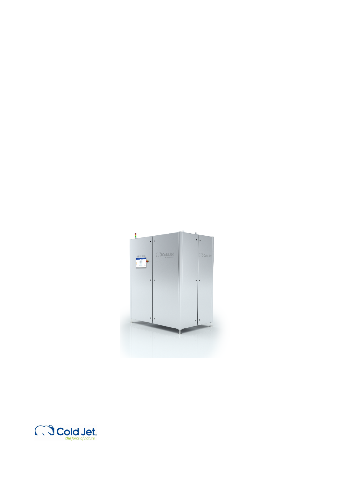
Cold Jet COMBI PCS 110 DUAL User manual


Copyright © 2021 Cold Jet, DK
All rights reserved. Printed in Denmark.
Due to continued product development this information may change without notice. The
information and intellectual property contained herein is confidential between Cold Jet and the
client and remains the exclusive property of Cold Jet. If you find any problems in the
documentation, please report them to us in writing. Cold Jet does not warrant that this
document is error-free.
No part of this publication may be reproduced, stored in a retrieval system, or transmitted
in any form or by any means, electronic, mechanical, photocopying, recording or otherwise
without the prior written permission of Cold Jet.
This manual reflects the product configuration as was current at the time of its writing. An
item’s display in this manual does not guarantee the item’s availability at any time in the
future. Images shown are for representation purposes only. Products may vary from the
images displayed. Cold Jet is not liable for typographical errors or changes to specifications
presented.
COMBI PCS 110 DUAL
Operator’s Manual
Version:
1.0
Page:
1 of 28
Date:
10.05.2021

Contents
INTRODUCTION 5
GENERAL INFORMATION 5
SYSTEM DESCRIPTION 7
Functional Description 7
Production Description 2A0388 7
SYSTEM IDENTIFICATION 9
Supplier Responsible for the Equipment 9
TECHNICAL DATA 10
SAFETY REGULATIONS 11
General Measures 11
Personnel Qualifications 11
Security and Risk 11
C02Safety 11
Electrostatic Discharge 12
Safety Labels 13
Danger of Suffocation 13
Static Electricity 14
Danger of Congelation 14
Wear Protective Gloves 14
SAFETY OPERATION 15
Emergency Stop 15
Machine Safety 15
Liquid CO2Leakage 15
Stop Production 15
Daily Checkup Before Start-up 15
MACHINE STRUCTURE 16
MACHINE CONTROL 17
Front Page 17
Start Up 18
COMBI PCS 110 DUAL
Operator’s Manual
Version:
1.0
Page:
2 of 28
Date:
10.05.2021

COMBI PCS 110 DUAL
Operator’s Manual
Version:
1.0
Page:
4 of 28
Date:
10.05.2021

INTRODUCTION
This manual should be kept with the machine and be readily accessible to machine operators. This manual
contains information on the safety and operation. The graphics used in this manual may show machine
details that may be different than the actual machine. Components of the machine may have been removed
for illustrative purposes or the continuing improvement of the machine’s design may cause changes that are
not included in this publication.
The owner of this machine is responsible for verifying the operator of this machine is properly trained and
understands the contents of this manual
GENERAL INFORMATION
The COMBI PCS 110 DUAL from Cold Jet presents a revolutionary alternative to existing dry ice production
and blasting machines in that it combines dry ice production and dry ice blasting in ONE MACHINE.
The COMBI PCS 110 DUAL provides a non-stop supply of high-density pellets. The source of raw material for
the production of pellets is liquid carbon dioxide conserved at low temperature in a storage tank. The liquid
CO2flows into the machine in a regulated manner and is transformed into CO2snow which is then pressed
through an extruder plate by means of the horizontal movement of a hydraulically driven piston.
The produced dry ice is then led into the two buffer tanks and blasted when activated by the control
system. The COMBI PCS 110 DUAL has a quick start-up that reduces downtime and loss of valuable CO2. This
is secured by a start-up sequence purging the liquid line and using a special valve to fill the chamber. The
machine also uses a heat exchanger for sub-cooling the liquid CO2, which enables higher CO2utilization and
a better liquid CO2ratio.
COMBI PCS 110 DUAL
Operator’s Manual
Version:
1.0
Page:
5 of 28
Date:
10.05.2021

The COMBI PCS 110 DUAL parts are protected by a moisture-free enclosure, which also reduces the noise
level to a minimum of 75 dB(a). Please note that the noise level, where the dry ice blasted, can overset a
noise level of 100 dB(a) depending on how the blasting function is installed and used.
The control system of the COMBI PCS 110 DUAL, is based on the Beckhoff Industrial PLC and HMI system,
which offers maximum functionality and a user-friendly interface. Production and blasting can be started by
pressing one button. Just in time production minimizes labor and waste during production and blasting.
COMBI PCS 110 DUAL
Operator’s Manual
Version:
1.0
Page:
6 of 28
Date:
10.05.2021

SYSTEM DESCRIPTION
The operator manual covers the COMBI PCS 110 DUAL. The main parts are described in the machine
structure section. Operating instructions for add-ons can be found in separate instructions and are not
included in this manual.
Functional Description
The main function of the COMBI PCS 110 DUAL is to produce dry ice pellets from liquid carbon dioxide and
dry ice blasting.
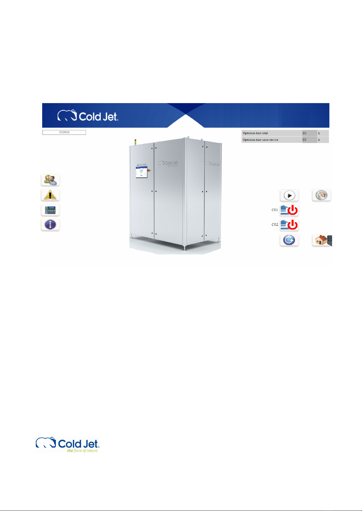
This is performed by a sequence of operations executed by the Beckhoff Panel PC. The Main steps in a
normal application are as follows and refer to the P&I diagram 2A0388, which is available through the
documentation packet or Cold Jet CONNECT.
1. Start up.
2. Production.
3. Blasting.
4. Standby.
5. Emptying.
6. Shutdown.
Production Description 2A0388
At every start-up the hydraulic cylinder =(G01-G1-MO1) for extruder piston is extracted to its max. position
to extrude the CO2snow in the chamber in case of an emergency stop or machine error.
Liquid CO2is fed from an external CO2tank (not part of this description – see supplier information) through
an insulated pipe to the COMBI PCS 110 DUAL. It is recommended to use a gas separator to eliminate
gaseous CO2from the liquid CO2.
When the hydraulic cylinder =(G01-G1-MO1) for extruder piston is retracted and hydraulic cylinder
=(G01-G1-MO2) for the extruder plate changes to the up position – CO2in valve =(W01-Q1) and injection
valve =(G01-Q1) will open and purge gaseous CO2through the chamber, and the degassing filters and via
degassing pipes to CO2out. When the temperature =(W01-TT2) in the liquid CO2is -14°C (6.8°F) the
injection will proceed until a timer is reached. Degassing valve =(G01-Q2) on extruder will open to reduce
chamber pressure before hydraulic cylinder =(G01-G1-M01) for extruder piston will extract until fast
forward pressure set point is reached and the hydraulic cylinder will again retract. This will continue until
the plug thickness set point is reached. When the plug thickness is reached the hydraulic cylinder
(G01-G1-M01) for extruder plate changer will move the extruder plate in its down position and production
of dry ice can commence. At start up mode the dry ice cutter =(V1-M1) starts up and the motor is running
continually during production.
In production mode the CO2in valve =(W01-Q1) and injection valve =(G1-Q01) will open until a timer is
reached. Degassing valve =(G01-Q2) on the extruder chamber will open to reduce chamber pressure
hydraulic cylinder =(G01-G1-M01) for extruder piston will extract until plug set point is reached and the
hydraulic cylinder will retract again. This cycle will continue until a different step is selected.
COMBI PCS 110 DUAL
Operator’s Manual
Version:
1.0
Page:
7 of 28
Date:
10.05.2021

When the machine starts to produce dry ice, it will begin filling up hopper tank =(C01-C1) or =(C02-C1)
depending on which hopper is selected in the program. As a default, hopper tank =(C01-C1) will be filled
first.
When sensor =(C01-C1-BL1) is active, the hopper tank =(C01-C1) is full. The blasting and emptying hopper
symbols on the control display become visible and you can now activate =(C01-C1-M1) for blasting or
emptying hopper. The hopper tank will be automatically filled again when sensor =(C01-C1-BL1) becomes
inactive.
When sensor =(C02-C1-BL1) is active, the hopper tank =(C02-C1) is full. The blasting and emptying hopper
symbols on the control display become visible and you can now activate =(C02-C1-M1) for blasting or
emptying hopper. The hopper tank will be automatically filled again when sensor =(C02-C1-BL1) becomes
inactive.
The shutdown sequence ensures that COMBI PCS DUAL 110 is stopped in a proper position to empty
extruder chamber from dry ice snow and avoid moisture in the extruder chamber. The hydraulic cylinder
=(G01-Q3-MO1) for extruder plate changer will move to the selected position and the hydraulic cylinder
=(G01-G1-MO1) for extruder piston will extract to max. position and return to shut down set point position.
The hydraulic cylinder =(G01-Q3-MO1) for extruder plate changer is in middle position and all valves are
closed.
Under the shutdown sequence the two hopper tanks are also emptied. This occurs when the two diverter
valves =(C01-Q1) and =(C02-Q1) changes position and will blast the dry ice into the CO2 drain pipes. This is
an automatic process which is activated when the machine is shutdown. The process will deactivate
automatically after a given time.
COMBI PCS 110 DUAL
Operator’s Manual
Version:
1.0
Page:
8 of 28
Date:
10.05.2021

SYSTEM IDENTIFICATION
The machine is double marked with EU and UL approval.
Supplier Responsible for the Equipment
Cold Jet ApS
Industrivej 68
DK-6740 Bramming
Denmark
Phone: +45 75 56 15 00
Homepage: www.coldjet.com
Email:inf[email protected]
COMBI PCS 110 DUAL
Operator’s Manual
Version:
1.0
Page:
9 of 28
Date:
10.05.2021

TECHNICAL DATA
Rated Output of Dry Ice:
kg/h: up to 120
lbs/h: up to 264,5
Depending on nozzle combination.
Inlet Liquid CO2Pressure:
Liquid CO2 Supply System
COMBI PCS 110 DUAL
Supply Pressure (Min-Max)
13-18 bar (189-261 psi)
Supply Pressure Range
+/- 1.0 bar (14.5 psi)
Supply Pressure (Recommended PBU Setting)
16,5 bar (240 psi)
Liquid CO2Dryness Fraction:
The water content should not exceed 35 ppm and should not be less than 5 ppm – or equivalent to a dew point
temperature of -66°C to -51°C (-86.8°F to -59.8°F).
NOTE:
The liquid CO2supply must be completely free of oil and must have a minimal purity of 99.9%.
Liquid CO2Supply Pipe:
Internal dia. 20 mm (0.8 inch), very well insulated with a minimum number of bends and fittings.
NOTE: If over 20 m (65.6 feet) in length, use an internal dia. of 25 mm (1 inch).
Power Supply:
3 x 380-480 V AC + PE, 50-60Hz,
TN-S Earthing system
Imax. 32 A
Air Supply:
Bar: min. 5 – max. 10
Psi: min 72 - 145
Rated Power:
15 kW / 20 Hp @3 x 400V AC
Rated Air Consumption:
Nm3/min: 3-11
Cfm: 106-388
Depending on nozzle combination.
Machine Dimensions:
Length: 1800 mm / 71 in
Width: 1200 mm / 47.3 in
Height: 2100 mm / 82.7 in
Height: 2200mm / 82.7 in (incl. ext. legs and pipes)
Weight: 1380kg / 3042 lbs
Noise level: below 75 dB(a)
COMBI PCS 110 DUAL
Operator’s Manual
Version:
1.0
Page:
10 of 28
Date:
10.05.2021

SAFETY REGULATIONS
General Measures
The COMBI PCS 110 DUAL manual contains instructions on starting up, operating and servicing the machine.
The operator must follow the instructions in the manual. Moreover, it is important that the owner makes
sure that the operator understands the contents of this manual and follows its guidelines and safety
regulations.
Personnel Qualifications
Employees who are in charge of mounting, operation, service and maintenance must be adequately
qualified to take care of such job functions.
If the employees do not possess sufficient knowledge, they must be instructed and trained properly. If
necessary, this can be arranged in cooperation with the manufacturer of the machine.
The owner of the machine shall make sure that the operator, who is to work with the COMBI PCS 110 DUAL,
fully understands the importance of complying with the SAFETY REGULATIONS described on the following
pages as well as those placed on the machine, and the importance of carefully studying the contents of the
manual before starting up the machine.
Security and Risk
The COMBI PCS 110 DUAL is designed so as to comply with the EC Declaration of Conformity for Machinery.
Therefore, using the machine does not pose a risk to the operator when the instructions in this manual are
followed carefully.
Installation must be carried out according to the instruction” Unpacking and preparations before
installation”.
The machine may only be installed by authorized personnel, that is electricians with knowledge of the
Council Directives 73/23/EEC and the 89/336/EEC and the 89/336/EEC (or similar directives in other parts of
the world).
C02Safety
This machine uses dry ice (CO2in solid form). The temperature of dry ice is -78.9°C (-109°F). Avoid
coming into direct contact with dry ice as it may cause severe tissue damage.
Study the material safety data sheet (MSDS) of dry ice (CO2) provided by the supplier and
COMBI PCS 110 DUAL
Operator’s Manual
Version:
1.0
Page:
11 of 28
Date:
10.05.2021

follow all the recommendations and guidelines listed therein.
COMBI PCS 110 DUAL
Operator’s Manual
Version:
1.0
Page:
12 of 28
Date:
10.05.2021

Operate the blaster in a well-ventilated work area with continuous CO2-level monitoring. The
effects of CO2are entirely independent of the effects of oxygen deficiency. Therefore, CO2
concentrations at 3-5% causes headaches, fast breathing and discomfort while higher
concentrations may cause unconsciousness, suffocation or respiratory arrest. The legal exposure
limit set by OSHA is a 0.5% average over an 8-hour workday and the acute (15 minute) exposure
limit set is 3.0%.
Always use a CO2monitoring/alarm system when working with machinery that emits CO2in a
confined room/space.
Electrostatic Discharge
Dry ice blasting may create electrostatic discharges. This machine is fitted with effective
electrostatic dischargers to prevent injury or damage. Also, the machine must be plugged into a
properly grounded electrical outlet.
It is recommended to avoid operating the machine near explosive or flammable material. Also,
use a plastic scooper when handling dry ice pellets to eliminate any electrostatic discharge.
COMBI PCS 110 DUAL
Operator’s Manual
Version:
1.0
Page:
13 of 28
Date:
10.05.2021

Safety Labels
The symbols used on the machine were developed by the International Organization for Standardization
(ISO) and are defined below. These symbols may include yellow warnings triangles, blue mandatory action
circles, or red prohibited action circles.
Danger of Suffocation
Dry ice pellets are CO2in solid form. At ordinary atmospheric pressure, CO2can only exist in this solid form
at temperatures of -78.9°C (-109°F) or lower. Therefore, during dry ice production and blasting, the CO2will
immediately be heated and thus transform from solid form into gas form.
Please note:
Since the specific gravity of CO2is higher than that of ordinary atmospheric air, the air with its contents of
oxygen will be replaced by CO2if the dry ice production is taking place in small or insufficiently ventilated
rooms.
Therefore, please note the following:
1. Low CO2concentrations (3-5%) cause headaches and fast breathing.
2. CO2concentrations of (7-10%) cause headaches and nausea and may result in unconsciousness.
3. Higher CO2concentrations result in unconsciousness and at worst, may cause suffocation.
High CO2concentrations may result in unconsciousness due to displacement of oxygen. Therefore, always
make sure to provide sufficient ventilation of the working area, and always avoid producing dry ice in small
rooms.
COMBI PCS 110 DUAL
Operator’s Manual
Version:
1.0
Page:
14 of 28
Date:
10.05.2021

Static Electricity
Dry ice can cause electrostatic discharges. However, the equipment is bonded to a ground to minimize
electrostatic discharge, and the warning sign is only meant to instruct the operator to avoid placing the
equipment in rooms containing explosive gasses.
Also, it is recommended to use a plastic shovel in the dry ice container.
Danger of Congelation
CO2in solid form has a temperature of -78.9°C /-109°F or lower at atmospheric pressure and can therefore
cause serious congelation injuries.
IMPORTANT!
Dry ice is extremely cold; therefore, do not touch parts of the machine which are in direct contact with the
dry ice without wearing appropriate protective clothing and gloves.
Wear Protective Gloves
During work with the conveyor system, the operator must wear protective gloves in order to avoid contact
with the dry ice or with parts of the machine which are in direct contact with the dry ice.
COMBI PCS 110 DUAL
Operator’s Manual
Version:
1.0
Page:
15 of 28
Date:
10.05.2021

SAFETY OPERATION
Emergency Stop
All equipment is connected to the general emergency system for the COMBI PCS 110 DUAL.
When an emergency-stop device is activated, all components located in the emergency zone will be
disconnected from their power source.
Machine Safety
There are machine safety measures in the following areas:
●Extruder unit
●Extruder plate changer
In this area, the protection is established with covers.
The covers are provided with locking screws, so that they can only open when using proper tools.
Required performance level PLr = c Implemented in category = Cat3.
There is danger of congelation / frost bites by touching machine parts cooled down by dry ice.
To prevent congelation, the entire machine enclosure is provided with locks and requires special tools to
open.
Liquid CO2Leakage
If liquid CO2is leaking from any point of the CO2pipe system, the CO2supply must be stopped immediately.
Localize the leakage and repair.
Stop Production
1. The machine is stopped by pressing the “Start / Stop” button.
NOTE: This will activate the shutdown procedure.
2. The CO2valve on the machine inlet will automatically close. It is recommended to close the manual
valve on the mounting kit before leaving the machine unused for a longer period of time.
3. Cut off the main electric supply.
NOTE:
Do not shut off the main switch on the cabinet inside the machine before the inlet CO2pressure is ZERO.
The CO2pressure can be checked on the “Process values” page.
Daily Checkup Before Start-up
1. Check the oil level in the sight glass.
COMBI PCS 110 DUAL
Operator’s Manual
Version:
1.0
Page:
16 of 28
Date:
10.05.2021

2. Check the pipe system for leaks.
3. Check the operation time since service intervals.
COMBI PCS 110 DUAL
Operator’s Manual
Version:
1.0
Page:
17 of 28
Date:
10.05.2021

MACHINE STRUCTURE
COMBI PCS 110 DUAL
1. Touch panel/ Emergency stop.
2. Dry ice blasting pipe.
3. Electrical connections and air connection.
4. Pipe connections.
5. Light tower.
COMBI PCS 110 DUAL
Operator’s Manual
Version:
1.0
Page:
18 of 28
Date:
10.05.2021

MACHINE CONTROL
This next section describes the functions of the HMI Screen for the operator level. The COMBI PCS 110
DUAL can only operate with external signals.
Before starting the machine always check the CO2lines and the power supply are connected. Then turn on
the machine.
Front Page
From the front page you have the option to go to the other pages. When you are on any other page and
need to return to the front page press the button for the front page.
COMBI PCS 110 DUAL
Operator’s Manual
Version:
1.0
Page:
19 of 28
Date:
10.05.2021
Other manuals for COMBI PCS 110 DUAL
1
This manual suits for next models
1
Table of contents
Other Cold Jet Industrial Equipment manuals

Cold Jet
Cold Jet PE50 User manual

Cold Jet
Cold Jet i3 MICROCLEAN User manual

Cold Jet
Cold Jet IceTech R1000H User manual

Cold Jet
Cold Jet IceTech Evolution Line Xcel 6 User manual

Cold Jet
Cold Jet E-CO2 150 User manual

Cold Jet
Cold Jet PR120H User manual

Cold Jet
Cold Jet i3 MICROCLEAN 2 User manual

Cold Jet
Cold Jet i3 MICROCLEAN User manual

Cold Jet
Cold Jet PR350H User manual

Cold Jet
Cold Jet Aero C100 User manual