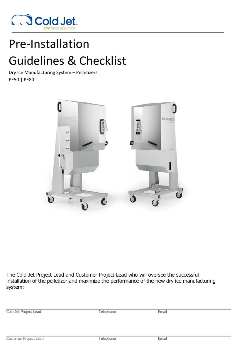
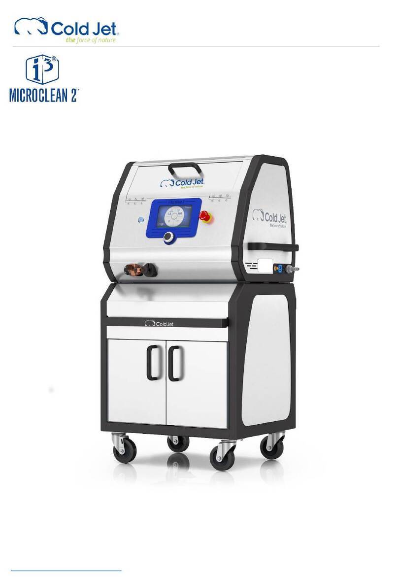
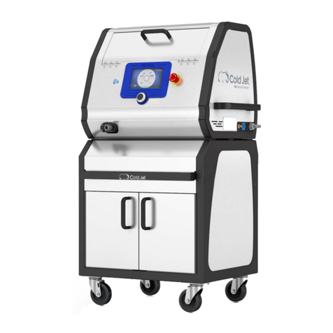
Cold Jet i3 MICROCLEAN User manual

2 2023-12-13
Click to go to Top of Document
Copyright © 2023 Cold Jet, LLC
All rights reserved. Printed in the USA.
Due to continued product development this information may change without notice. The information and
intellectual property contained herein is confidential between Cold Jet and the customer and remains the
exclusive property of Cold Jet. If you find any problems in the documentation, please report them to us in
writing. Cold Jet does not warrant that this document is error-free.
No part of this publication may be reproduced, stored in a retrieval system, or transmitted in any form or
by any means, electronic, mechanical, photocopying, recording or otherwise without the prior written
permission of Cold Jet.
This manual reflects the product configuration as was current at the time of its writing. An item’s display in
this manual does not guarantee the item’s availability at any time in the future. Images shown are for
representation purposes only. Products may vary from the images displayed. Cold Jet is not liable for
typographical errors or changes to specifications presented.
Contents
System Identification____________________________________________________________________________________4
Introduction _____________________________________________________________________________________________5
Safety ____________________________________________________________________________________________________5
General Safety Guidelines ____________________________________________________________________________5
CO2Safety _____________________________________________________________________________________________6
Electrostatic Discharge _______________________________________________________________________________7
Electrical Grounding __________________________________________________________________________________7
Safety Labels __________________________________________________________________________________________7
Cautions and Warnings _______________________________________________________________________________8
Lockout Tagout______________________________________________________________________________________ 10
System Description____________________________________________________________________________________ 11
Machine Data _______________________________________________________________________________________ 11
Machine Components_______________________________________________________________________________ 12
Control Panel________________________________________________________________________________________ 13
Applicator Components_____________________________________________________________________________ 14
Nozzles ______________________________________________________________________________________________ 15
Operation______________________________________________________________________________________________ 16
Unpacking the Machine_____________________________________________________________________________ 16
Machine Setup ______________________________________________________________________________________ 17
The Compressed Air Supply_________________________________________________________________________ 18
Starting the Machine________________________________________________________________________________ 21
Blasting Dry Ice______________________________________________________________________________________ 22
3 2023-12-13
Click to go to Top of Document
Shutting Down the Machine ________________________________________________________________________ 22
Cold Jet CONNECT® ___________________________________________________________________________________ 23
Maintenance___________________________________________________________________________________________ 25
Troubleshooting _______________________________________________________________________________________ 25
Unclog the Dry Ice Chute ___________________________________________________________________________ 26
Pellet and Nugget Shaving ____________________________________________________________________________ 27
Warranty Policy________________________________________________________________________________________ 29
Schematics_____________________________________________________________________________________________ 30
Contact Information___________________________________________________________________________________ 37

4 2023-12-13
Click to go to Top of Document
System Identification
Locate the data plate for this machine and record the information provided in the spaces below.
ASSEMBLY No.
SERIAL No.
VOLTS AC
AMPS
PHASE
FREQ (Hz)
HP
FULL LOAD AMPS
MOTOR AMPS
SHORT CIRCUIT INTERRUPTING CAPACITY
SHORT CIRCUIT CURRENT CAPACITY
MAX CO2 TEMP
MAX OPERATING PRESSURE
SHIPPING WEIGHT
MANUFACTURE DATE

5 2023-12-13
Click to go to Top of Document
Supplier Responsible for the
Equipment:
Cold Jet, LLC
455 Wards Corner Road
Loveland, Ohio 45140 USA
Phone: 1-800-777-9101
Website: www.coldjet.com
Introduction
About This Manual
•This manual should be kept with the machine and be readily accessible to machine operators and
maintenance personnel.
•This manual contains information on the safety, transportation, operation, and maintenance of
this machine.
•The graphics used in this manual may show machine details that may be different than the actual
machine. Components of the machine may have been removed for illustrative purposes or the
continuing improvement of the machine’s design may cause changes that are not included in this
publication.
•The owner of this machine is responsible for verifying the operator of this machine is properly
trained and understands the contents of this manual.
Environmental Impact
Dry ice is a clean and non-toxic medium approved by the EPA, USDA, and FDA. The dry ice used in this
machine is made from reclaimed CO2 generated from other industrial processes.
Safety
General Safety Guidelines
•This machine is designed to comply with international design standards and the European
Machinery Directives.
•Using the machine does not pose a risk to the operator when the instructions in this manual are
followed. However, certain precautions must be taken during its use. To understand all the
necessary precautions, the machine operator must read the entire manual before operating or
performing maintenance on the machine.

6 2023-12-13
Click to go to Top of Document
•Operation should only be performed by trained personnel. Below are some basic safety
guidelines:
oFollow local governing codes to ensure a minimum standard of safety.
oWear protective gloves, eye protection, hearing protection, and protective clothing.
oOperate the machine in a well-ventilated work area.
oFollow the prescribed inspection schedule.
oStart up and shut down the machine according to the instructions in this manual.
oDo not operate a machine that is damaged or in disrepair.
oDo not store objects on top of machine.
CO2Safety
WARNING - Ensure adequate ventilation when operating this equipment to
prevent the build-up of carbon dioxide gas. If used indoors or in other
confined spaces, a CO2detector should be used to monitor excessive, unsafe
levels of CO2gas and provide a suitable warning. The legal exposure limit by
OSHA is a 0.5% average over an 8-hour workday.
•This machine uses dry ice (CO2in solid form). The temperature of dry ice is -109°F (-78.9°C).
•Avoid coming into direct contact with dry ice as it may cause severe tissue damage. Study the
material safety data sheet (MSDS) of dry ice (CO2) supplied with the delivery of dry ice and follow
all the recommendations and guidelines listed therein.
•Operate the blaster in a well-ventilated work area with continuous CO2-level monitoring.
•The effects of CO2are entirely independent of the effects of oxygen deficiency.
•CO2concentrations at 3-5% causes headaches, fast breathing, and discomfort while higher
concentrations may cause unconsciousness, suffocation, or respiratory arrest. The legal
exposure limit set by OSHA is a 0.5% average over an 8-hour workday and the acute (15 minute)
exposure limit is 3.0%.
•Always use a CO2monitoring/alarm system when working with machinery that emits CO2in a
confined room/space.

7 2023-12-13
Click to go to Top of Document
Electrostatic Discharge
WARNING - Dry ice blasting may create electrostatic discharges which may
harm personnel. Ensure that the surfaces being cleaned are properly
grounded with the supplied grounding cable. This machine is fitted with
effective electrostatic dischargers to prevent injury or damage. It is
recommended to avoid operating the machine near explosive or flammable
material. Also, use a non-metallic scoop when handling dry ice to eliminate
any electrostatic discharge.
Electrical Grounding
WARNING - To prevent electrical shock, the machine must be properly
grounded using outlets and power cords that have a ground lug. The
machine must be plugged into a properly grounded outlet. If there is no
ground connection, DO NOT USE.
Safety Labels
The symbols used on the machine were developed by the International Organization for
Standardization (ISO) and are defined below. These symbols may include yellow warning triangles, blue
mandatory action circles or red prohibited action circles. Replace any safety labels or warning signs if
they become damaged, missing, or illegible. Contact Cold Jet’s customer service department to obtain
replacement labels.
Symbol
Definition
Hand Entanglement Chain Drive
Electrical Shock

8 2023-12-13
Click to go to Top of Document
Symbol
Definition
Explosive Release of Pressure
Skin Puncture/Pressurized Jet
Attention
Hand Crush
Debris
Static Shock
Blade
Cold Temperature Warning
Cautions and Warnings
Please review the following cautions and warnings before operating or performing maintenance on the
machine.
CAUTION
Read the entire operator manual before using the machine. Only qualified personnel
should operate the machine.
WARNING
Ensure adequate ventilation when operating this equipment to prevent the build-up of
carbon dioxide gas. If used indoors or other confined space, a CO2detector should be
used to monitor for excessive unsafe levels of CO2gas and provide a suitable warning.
The legal exposure limit by OSHA is a 0.5% average over an 8-hour workday and the
acute (15 minute) exposure limit is 3.0%.

9 2023-12-13
Click to go to Top of Document
WARNING
Ensure that expended dry ice emissions are not in the vicinity of air ducts that could
allow CO2to enter another space.
WARNING
Due to the nature of dry ice and atmospheric conditions, use caution when operating,
storing, and cleaning the machine as condensate can build up and leave moisture on
the ground near the machine and blast hose. It is recommended to wear appropriate
non-slip work shoes and it is necessary to wipe up and dry any condensate from the
work area that could cause a slip hazard.
WARNING
The use of other cleaning agents or chemicals may adversely affect the safety of the
machine.
WARNING
High pressure blast streams can be dangerous if subject to misuse. The blast stream
must never be directed at persons, live electrical equipment, or the machine itself.
WARNING
Do not use the machine within range of persons unless they wear the required
personal protective equipment (PPE).
WARNING
This machine should not be operated by or left unattended around children or
untrained personnel.
WARNING
High pressure hoses, fittings, and couplings are important for the safety of the machine.
Use only hoses, fittings, and couplings supplied by Cold Jet.
WARNING
To ensure machine safety, use only original and replacement parts from Cold Jet.
WARNING
The applicator and blast hose contain electrical connections. Do not immerse in water.
WARNING
Only use Cold Jet applicators, nozzles, and hoses.
WARNING
Do not use the machine if an electrical supply cord or important parts of the machine
are damaged or missing, e.g., safety devices, side panels, guards, high pressure hoses,
applicator, hardware, nuts, bolts, screws.
WARNING
Inadequate extension cords can be dangerous. If an extension cord is used, it must be
suitable for the environment in which it is used. If used outdoors the connection must
be kept dry and off the ground. It is recommended that this is accomplished by means

10 2023-12-13
Click to go to Top of Document
of a cord reel which keeps the socket at least 2.4 inches (60 mm) above the ground.
Ensure that the extension cord is properly sized for the machine electrical
requirements.
WARNING
Always switch off the main disconnecting switch, or unplug the power cord, bleed any
pressure, and disconnect the air supply when leaving the machine unattended or
shutting down. Reel the power cord up to the machine and place a locking device over
the plug of the unit when Lockout Tagout is necessary.
WARNING
Ensure all machine covers are in place before operating the machine.
Lockout Tagout
•Throughout this manual, Lockout Tagout will be referred to in instances when power must be
removed from the machine.
•There are universally accepted basics to this procedure. The minimum steps are listed below but
may not be limited to these steps; each individual entity owning and/or operating a machine
may have their own additional procedures.
NOTE: There are two energy sources that supply the machine –an electrical supply and a compressed
air supply. Both energy sources must be removed.
1. Shut Down: Use the machine’s power button to turn off power.
2. Isolation:
a. Unplug the power cord from the supply source.
b. Leave the power cord within visual distance of the machine.
c. Turn off the compressed air supplying the machine.
d. Turn the air bleed knob on the right side of the machine to the vertical (open) position.
e. Disconnect the compressed air supply.

11 2023-12-13
Click to go to Top of Document
3. Check for Stored Energy: At the applicator, press the “Air-Only” once, pull the trigger. No activity
should be present at the machine.
4. Isolation Verification: Does the machine have electric power or compressed air present? The
power button should not be lit; it should be off. At the applicator, press the “Air-Only” once, pull
the trigger. No activity should be present at the machine.
5. Verify the reason for using the Lockout Tagout procedure has been solved. Once you
verify that the problem is solved, follow the instructions in the Starting the Machine section of
this manual.
System Description
Machine Data
Dimensions
22 x 16 x 21 in (560 x 410 x 530 mm)
Machine Weight
130 lb. (59 kg)
Dry Ice Capacity
For 6 x 6 x 12 in (150 x 150 x 300 mm) blocks –24.5 lb. (11 kg)
For 5 x 5 x 12 in (127 x 127 x300 mm) blocks with inserts –16.5 lb. (7.5 kg)
Variable Feed Rate
0 –1.2 lb./min (0-0.6 kg/min)
Power Consumption
100 –140 VAC, 1PH, 60 Hz, 300 W
200 –240 VAC, 1 PH, 50 Hz, 300 W
Feeder Drive
¼ Hp, 1.1 A. 230 VAC, 750 RPM, AC Motor
Blast Pressure Range
20 –140 psi (1.4 –9.7 bar)
Supply Pressure Range
50 –140 psi (3.4 –9.7 bar)
Air Consumption Range
12-50 cfm @ 100 psi (0.3 –1.4 m3/min @ 6.9 bar)
Blast Pressure Range
20 - 145 psi (1.4 - 10 bar)

12 2023-12-13
Click to go to Top of Document
Machine Components
1
2
6
5
8
7
9
3
4
1. Applicator Hook
2. Safety Guard Lock
3. Chute Access Port
4. Carrying Handle
(Two Person Lift)
5. Ventilation
6. Blast Pressure Gauge
7. Blast Pressure
Regulator
8. Control Cable
Connection Port
9. Blast Hose
Connection Port
10. Dry Ice Block Level Indicator
11. Fill Lid
12. Bleed Valve
13. Air Supply Hose Connection
10
11
12
13

13 2023-12-13
Click to go to Top of Document
Control Panel
Control Panel Legend
1. Main Power Switch (I = ON, O = OFF)
2. Power On Indicator Light
3. Applicator Light Switch (I = ON, O = OFF)
4. Dry Ice Feed Rate Knob
5. Disable Applicator
oPush button in to disable applicator [Blue light ON] –Applicator will not work.
oPull button out to enable applicator [Blue light OFF] –Applicator will work.
6. Hour Meter
1
2
3
4
5
6

14 2023-12-13
Click to go to Top of Document
Applicator Components
1
2
3
6
7
1. LED Light
2. Nozzle Connector
3. Trigger with Safety Switch
NOTE: The applicator trigger has a safety switch that must be depressed first
before the trigger will activate.
4. Control Cable Connection
5. Blast Hose Connection
6. Hanger
7. Mode Select Switch
| - Air Only
O –Off
|| - Air + Ice
4
5

15 2023-12-13
Click to go to Top of Document
Nozzles
•There are many different nozzles available, depending on what is being cleaned and how
accessible it is. Specialty nozzles are also available. Contact Cold Jet's customer service
department to determine the nozzle that may be most effective for your application.
Nozzle
Air Consumption
Blast Swath
Dry Ice Feed Rate
Length
Material
(MC13)
Yellow
12 CFM@80 psi
(0.3
m
3
/min
5.5
bar)
0.13
in
(.3
cm)
0.1-0.4 lbs/min
.05-0.2 kg/min
6 in
(15.2
cm)
Plastic
(MC19)
White
30 CFM@80 psi
(0.8
m
3
/min
5.5
bar)
0.19
in
(.5
cm)
0.2-1.0 lbs/min
0.1-0.5 kg/min
6 in
(15.2
cm)
Plastic
(MC31)
Blue
50 CFM@80 psi
(1.5
m
3
/min
5.5
bar)
0.31
in
(.8
cm)
0.5-1.2 lbs/min
0.2-0.6 kg/min
6 in
(15.2
cm)
Plastic
Fan Nozzles
(MC47)
25 CFM@80 psi
(0.7 m
3
/min 5.5 bar)
Fan
0.47
in
(1.2
cm)
0.2-1 lbs/min
0.1-0.5 kg/min
6 in
(15.2
cm)
Plastic &
Aluminum
(MC28)
25 CFM@80 psi
(0.7 m
3
/min 5.5 bar)
Fan
.28
in
(.7
cm)
.2-1 lbs/min
0.1-0.5 kg/min
6 in
(15.2
cm)
Plastic &
Aluminum
(MC35)
25 CFM@80 psi
(0.7 m
3
/min 5.5 bar)
Fan
0.35
in
(.9
cm)
0.2-1 lbs/min
0.1-0.5 kg/min
6 in
(15.2
cm)
Plastic &
Aluminum
(MC88F)
25 CFM@80 psi
(0.7 m
3
/min 5.5 bar)
Fragmenting Fan
0.88
in
(2.2)
cm
0.2-1 lbs/min
0.1-0.5 kg/min
5 in
(12.7
cm)
Plastic &
Aluminum
(MC88)
30 CFM@80 psi
(0.9 m
3
/min 5.5 bar)
Fan
0.88
in
(2.2
cm)
0.5-1.2 lbs/min
0.2-0.6 kg/min
5 in
(12.7
cm)
Plastic &
Aluminum

16 2023-12-13
Click to go to Top of Document
Operation
Unpacking the Machine
This machine has been assembled and tested as one unit prior to shipment. Follow the steps below to
inspect and unpack the machine from the shipping container.
1. Examine the shipping container for any damage that may have occurred during transport.
2. Remove the machine. Recycle boxes and packaging.
3. Examine the machine for any external damage that may have occurred during transport.
Refer to the packing slip for a list of the components shipped with the machine. Contact Cold Jet if any
damage has occurred to the shipping container or the machine or if any components are missing.
Nozzle
Air Consumption
Blast Swath
Dry Ice Feed Rate
Length
Material
Angled Nozzles
(MC25A45)
25
CFM
0.7
m
3
/min
0.25
in
(.6
cm)
0.2-1 lbs/min
0.1-0.5 kg/min
6 in
(15.2
cm)
Aluminum
(MC25A90)
25
CFM
0.7
m
3
/min
0.25
in
(.6
cm)
0.2-1 lbs/min
0.1-0.5 kg/min
6 in
(15.2
cm)
Aluminum
Advanced Nozzles
(MC26M)
35
CFM
1.0
m
3
/min
0.26
in
(.7
cm)
0.2-1.2 lbs/min
0.1-0.6 kg/min
5 in
(12.7
cm)
Plastic &
Aluminum
(MC29MH)
50
CFM
1.5
m
3
/min
0.29
in
(.7
cm)
0.5-1.2 lbs/min
0.2-0.6 kg/min
6 in
(15.2
cm)
Plastic &
Aluminum

17 2023-12-13
Click to go to Top of Document
Machine Setup
Improper installation of the machine or the applicator could cause injury to
the operator.
Follow Lockout Tagout procedures and always shut off the air pressure
while attaching or disconnecting hoses or fittings to the machine.
Prior to disconnecting the air supply hose, ensure the air pressure has
been shut off and pressure bled from the hose. The air hose is normally
pressurized while in idle or in operation.
1. Position the machine close to the surface being cleaned.
2. Make sure the power switch is in the off position.
3. Turn the air bleed
valve to the horizontal
closed position.
4. Attach the blast hose and control cable to the machine.
5. Connect the blast hose to the applicator by threading the blast hose onto the end of the applicator.
6. Align the pins of the control cable connector with the pins on the end of the applicator, press
together and rotate clockwise until fully locked.
7. Attach a nozzle to the applicator.
8. Attach the static bond cable to the target surface and an electrically conductive support structure.
WARNING
WARNING

18 2023-12-13
Click to go to Top of Document
9. Attach the air supply hose to the port on the right side.
10. Attach the power cord to the machine and then to a properly grounded electrical outlet.
11. Turn the air supply on and allow the air hose to pressurize.
12. Go to the Starting the Machine section of this manual.
The Compressed Air Supply
•Although Cold Jet dry ice equipment is designed and engineered to work under the most
demanding environments and conditions, the incoming air supply must be as free of oil,
dirt/foreign particles, and water/moisture as possible.
oFor example, oil-laden air will contaminate the entire system including any articles being
dry ice blast cleaned.
•Contaminants such as dirt/foreign particles will score or even clog interior mechanical parts
resulting in poor machine function.
•Dirt/foreign particles in the compressed air can strike the article causing damage to the surfaces
being dry ice blast cleaned.
•The results of frozen water and/or moisture can be:
o“Water-ice” - It is a very good adhesive; internal parts may freeze together and seize the
machine.
oLoose water-ice pieces could build up and cause clogs in the hose, particle control
assembly, feeder and/or nozzle.
oWater-ice is harder than dry ice and may cause damage to the article being dry ice
cleaned.
oWhen water-ice melts, water is left behind. (Dry ice sublimates, meaning it turns to a gas.)
Water can be a slip hazard and may increase the speed at which corrosion may occur.
•Particular attention must be paid to water. Water or moisture laden air can be especially
troublesome once it is introduced to dry ice. (In this case, “moisture” is referred to as water in
vapor form.) For example, dry ice is -109F (-78C), water/moisture will immediately freeze and may
cause problems.
•The incoming air quality must meet the standards in the chart provided in the Required Air Quality
section of this manual. In addition, it is recommended that the incoming supply air and any

19 2023-12-13
Click to go to Top of Document
associated filters and water separators that may be used are continuously monitored to ensure
the machine receives the air required for proper machine function. If these air quality
specifications are not met and poor air quality air continues to be used with Cold Jet equipment,
the warranty will be nullified.
Required Air Quality
One micron = .00003in. (.001mm)
Symbol: µ
Example: Human hair = 70µ
Understanding the effects of the surrounding environment
•Although Cold Jet dry ice equipment is designed and engineered to work under the most
demanding environments and conditions, temperature, humidity, dust, and other contaminants
present in the surrounding air can have an adverse effect on dry ice blasting equipment.
•Temperature and humidity: You may be familiar with a hot, sticky mid-summer day. These days
have high temperatures and high humidity. How does this affect dry ice blasting equipment?
Understanding “Dew Point” will answer this question.
•“Dew Point” - The temperature the air needs to be cooled to (at constant pressure) to achieve a
relative humidity of 100%. At this point the air cannot hold more moisture in the gas form and
water droplets form.

20 2023-12-13
Click to go to Top of Document
oAir compressors generally draw air from its surrounding environment. Once the air
passes through the compressor, it is warmed even further due to the mechanical friction
of the compressor’s internal mechanisms.
oAs the compressed air travels through pipes or hoses towards its destination it starts to
cool down. As it cools, it may reach its dew point, when moisture will change from vapor
form to liquid form.
oThe specific dew point will vary based on temperature and humidity, but it is certain that
this natural phenomenon will occur as warm, moist air cools. And, if it is possible to cool
the air even further such as using a Cold Jet aftercooler, more moisture is turned to water
that can be separated from the compressed air. The result is less moisture, in any form,
to negatively affect the dry ice blasting equipment.
Signs of water/moisture in the compressed air stream.
•Water coming from the nozzle while blasting Air-Only and/or with dry ice.
•Water running out of any of the hose connections or the hoses themselves.
•Water-ice building up on the tip of the nozzle and getting longer as blasting continues.
•Periodic stopping of dry ice flow/blasting.
•“Sputtering” of water ice or dry ice coming from the nozzle.
•Complete feeder blockage.
Humidity in the surrounding air:
•The higher the humidity, the higher the moisture content in the surrounding air. This not only
affects the compressed air quality on the internal surface of the equipment but on the dry ice
itself.
•Humidity (moisture in the air) that seeps into the trough will settle on the dry ice. The result is
that the moisture freezes on the dry ice pellets or blocks causing them to stick together. A sign
of this is dry ice that is not free flowing but rather presents itself as one or more large masses.
NOTE –Do not use a foreign object such as a stick or metal rod to break up the ice. Contact
Cold Jet’s customer service department.
Other manuals for i3 MICROCLEAN
2
Table of contents
Other Cold Jet Industrial Equipment manuals

Cold Jet
Cold Jet E-CO2 150 User manual

Cold Jet
Cold Jet PR350H User manual

Cold Jet
Cold Jet i3 MICROCLEAN User manual

Cold Jet
Cold Jet PE50 User manual

Cold Jet
Cold Jet i3 MICROCLEAN 2 User manual

Cold Jet
Cold Jet PR750H User manual

Cold Jet
Cold Jet P1500 User manual

Cold Jet
Cold Jet Aero C100 User manual

Cold Jet
Cold Jet PR120H User manual

Cold Jet
Cold Jet IceTech R1000H User manual