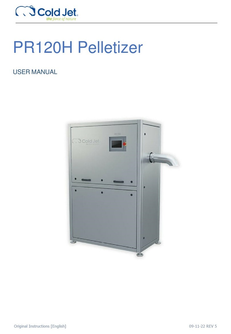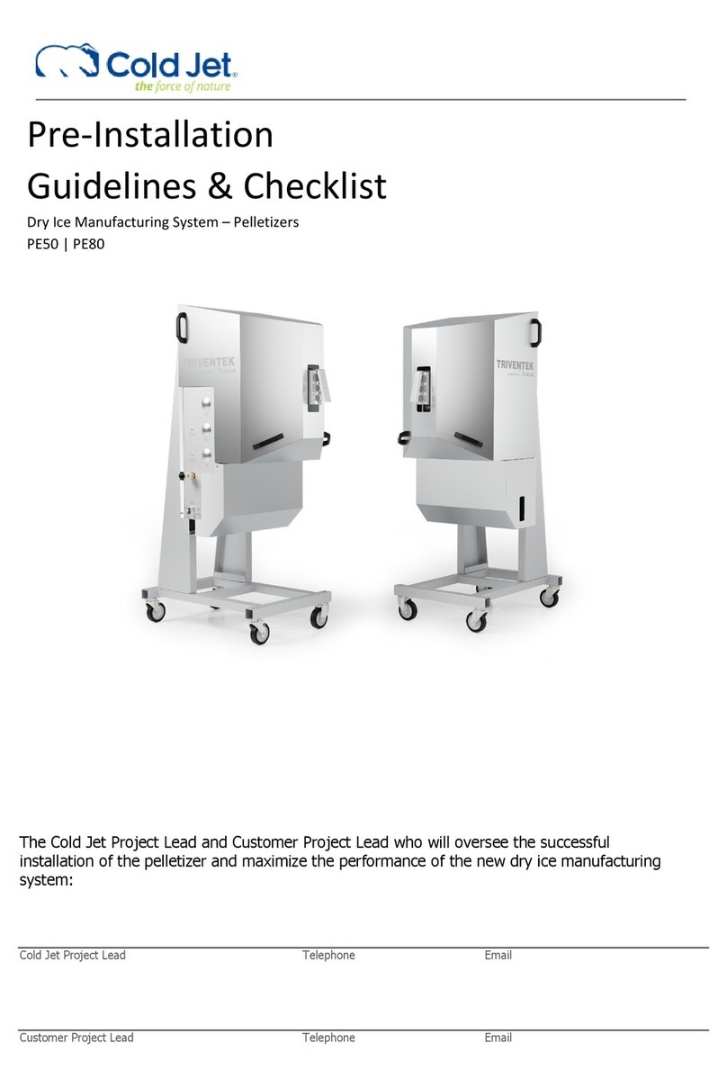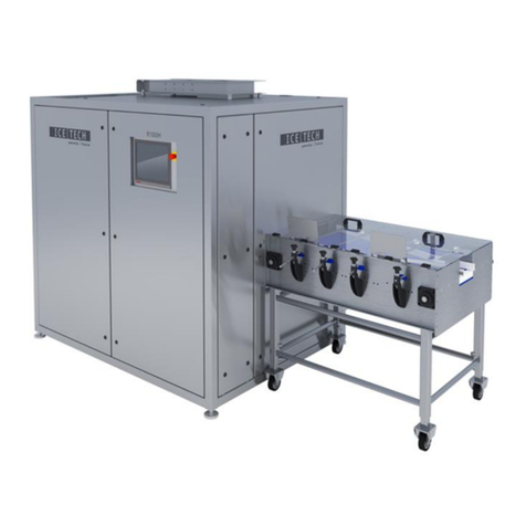
PR750H
User manual
Version: 5
Page: 5 of 21
Date: 2023.05.25
SYSTEM DESCRIPTION
This operator manual covers the PR750H operating instructions. The main parts are described in the machine structure
section. Operating/User instruction for add-ons can be found in other materials not included in this manual.
Functional description
The main function of the PR750H is to produce dry ice pellets from liquid carbon dioxide. This is performed by
a sequence of operations executed by the Beckhoff IPC. The main steps during normal production are as follows and refer
to PI diagram 2A0510 and 2A0511 for PR750H:
1. Start-up
2. Production
3. Standby
4. Shut down
At every start-up, the hydraulic cylinder =G01-G1-MO1 for the extruder piston is extracted to its maximum position to
extrude the CO
2
snow in the chamber in case of an emergency stop or machine error.
Liquid CO
2
is fed from an external CO
2
tank (not part of this description – see supplier information) through an insulated
pipe to the PR750H. It is recommended to use a gas separator to expel gaseous CO
2
from the liquid CO
2
.
When the hydraulic cylinder =G01-G1-MO1 for extruder piston is retracted and hydraulic cylinder =G01-Q3-MO1 for
extruder plate changer is in the middle position - CO
2
In valve =W01-Q1 and Injection valve =G01-Q1 will open and purge
gaseous CO
2
through the chamber, degassing filters via degassing pipes to the CO
2
out. When temperature =W01-TT1 in
the liquid CO2 is -14°C injection will proceed until the timer is reached. The degassing valve =G01-Q5 on the extruder
chamber will open to reduce chamber pressure before the hydraulic cylinder =G01-G1-MO1 so the extruder piston will
extract until fast forward pressure set point is reached and the hydraulic cylinder will again retract. This will continue until
the plug thickness set point is reached. When plug thickness is reached the hydraulic cylinder =G01-Q3-MO1 for the
extruder plate changer will move to the selected extruder plate position and production will commence.
In production mode CO
2
In valve =W01-Q1 and the Injection valve =G01-Q1 will open until the timer is reached. The
degassing valve =G01-Q5 on the extruder chamber will open to reduce chamber pressure before the hydraulic cylinder
=G01-G1-MO1 for the extruder piston will extract until plug set point is reached and the hydraulic cylinder will again retract.
This cycle will continue until a different step is selected. During production, it is possible to set the PR750H on standby.
When the maximum standby time is reached, the PR750H will run a shutdown sequence.
The shutdown sequence ensures that PR750H is stopped in a proper position to empty the extruder chamber of dry ice
snow and avoid moisture in the extruder chamber. The hydraulic cylinder =G01-Q3-MO1 for the extruder plate changer
will move to the selected position and the hydraulic cylinder =G01-G1-MO1 for the extruder piston will extract to the
maximum position and return to shut down setpoint position. The hydraulic cylinder =G01-Q3-MO1 for the extruder plate
changer is in the middle position and all valves are closed.
