Coleman 011-2044-8 User manual

400 Watt WIND TURBINE
User’s Manual

Congratulations on your Coleman® solar product purchase. This product is designed to
the highest technical specifications and standards. It will supply years of maintenance free
use. Please read these instructions thoroughly prior to installation, then store in a safe
place for future reference. If at any time you are unclear about this product, or require
further assistance please do not hesitate to contact our trained professionals operating the
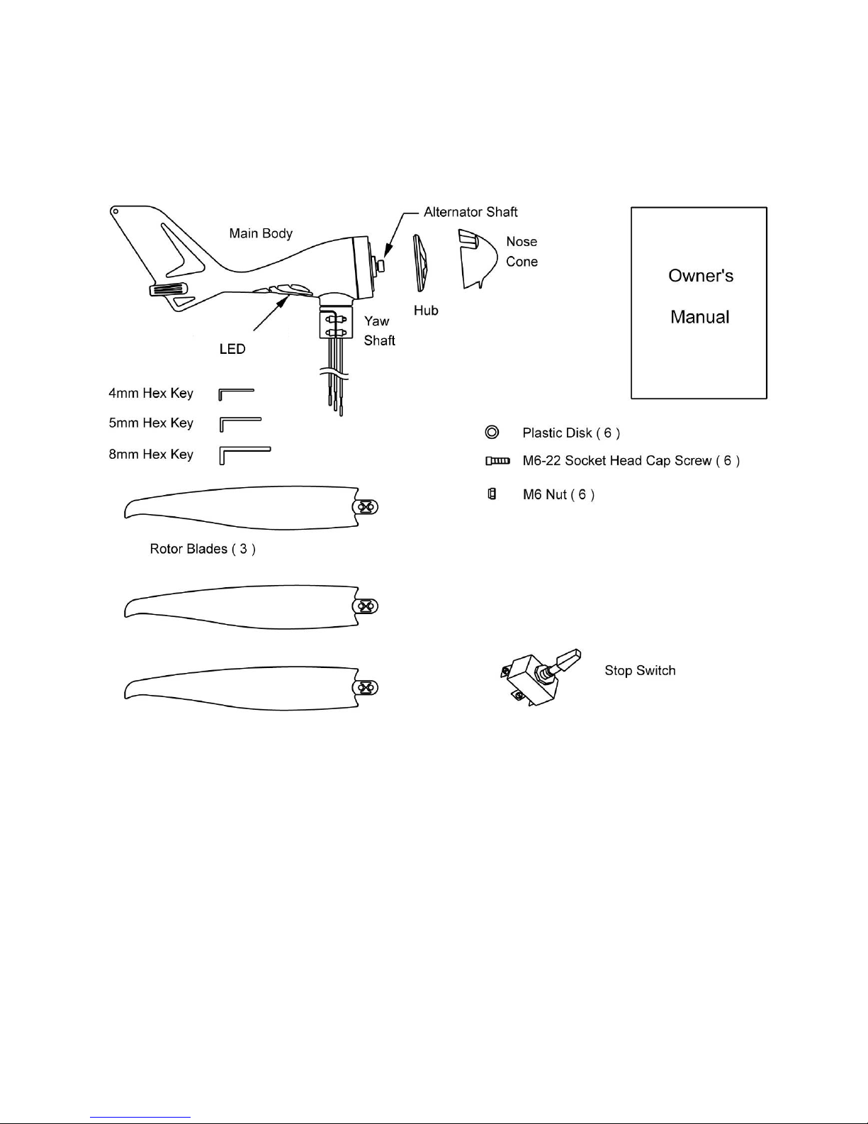
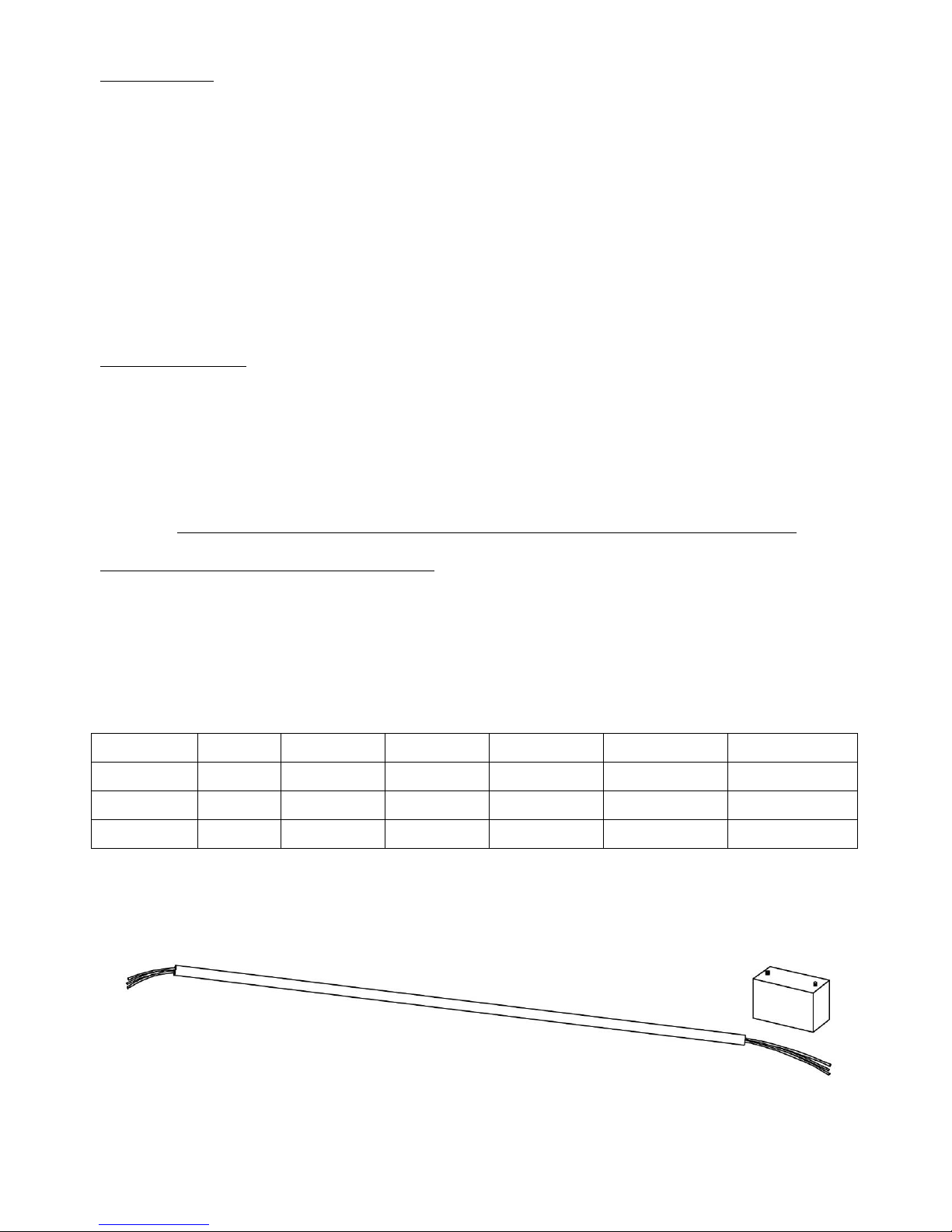
ACCESSORIES INCLUDED
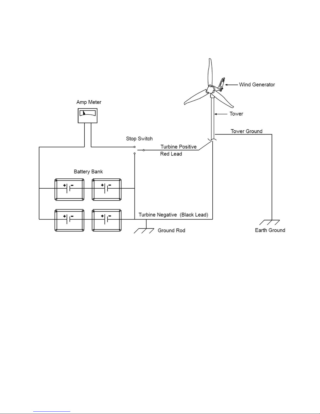
Stop Switch: 50 amp DC stop switch. This is used to safely apply a brake to your turbine,
during either periods of intense wind or general maintenance
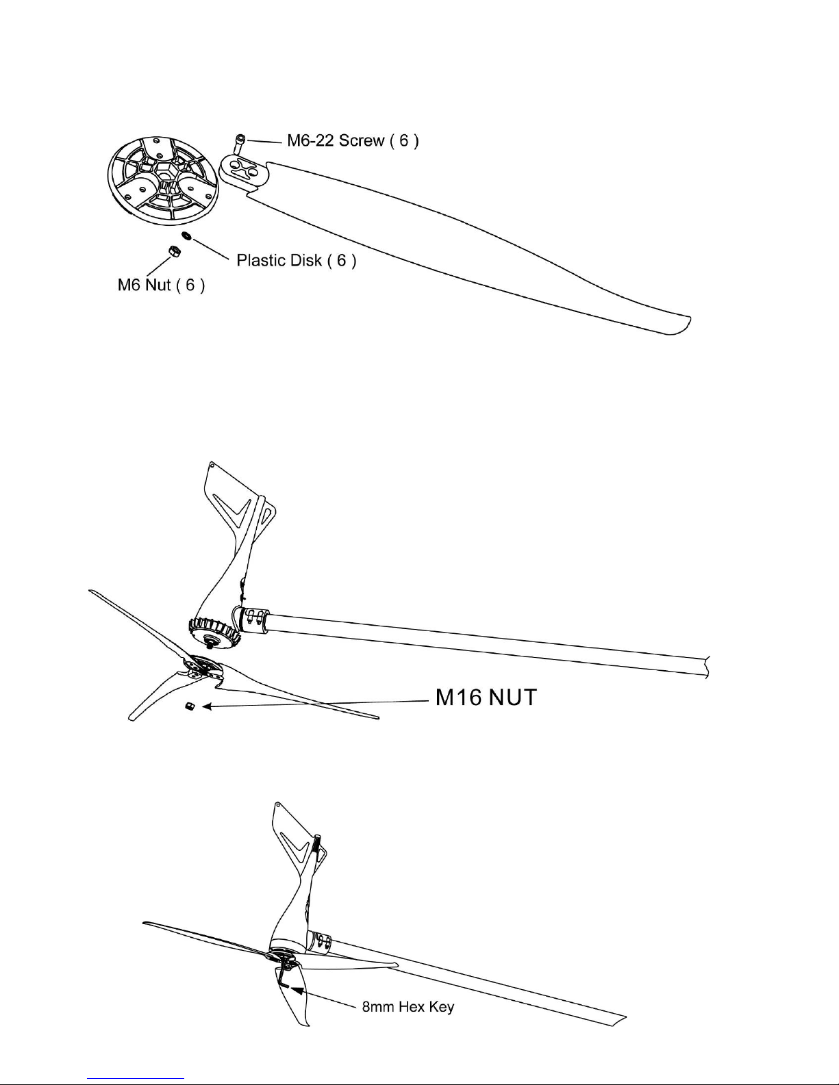
Plastic Disks: Anti static plastic components, that will prolong the life span of the turbine
protecting from weather corrosion and static build up.
Your Coleman Wind Turbine is designed with your personal safety as the first priority.
However, there are still some inherent dangers involved with any electrical and/or
mechanical equipment.
Safety must be the primary concern as you plan the location, installation and operation of
the turbine. Please read the following:
Important Safety Instructions
Please take the time to read through this manual prior to assembly.
1) Place this instruction manual in a safe place for reference.
2) Wait until a calm day to install or perform maintenance on your Turbine.
3) Listen to your Turbine should you hear any mechanical noise, maintenance may be
required, please contact Sunforce Products Customer Service.
4) After installation re-adjust and tighten the screws and bolts.
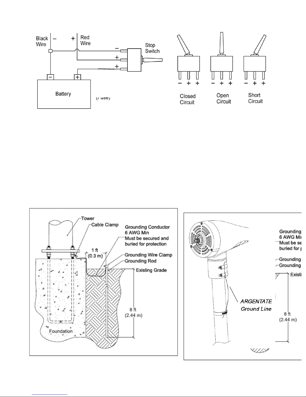
5) Adhere to proper grounding techniques as established by the NEC.
6) Your Coleman Wind Turbine must be installed in accordance with this manual and
local and national building code. Incorrect installation may void your warranty.
7) Wind turbine blades spin at a potentially dangerous speed. Installation instructions
must therefore be followed carefully and respected. Never approach a turbine in motion.
Mechanical Hazard
Rotating blades present the most serious mechanical hazard. The rotor blades are made of
very strong thermoplastic. At the tip, the blades may be moving at velocities over 15m/s. At
this speed, the tip of a blade is nearly invisible and can cause serious injury. Under no
circumstances should you install the turbine where a person could come in contact with
moving rotor blades.
Electrical Hazard
The Coleman Wind Turbine is equipped with sophisticated electronics designed to provide
protection from electrical dangers. Please note that the inherent personal dangers from
electrical current still exist, therefore caution should always be used when connecting this
and other electrical devices.
Heat in a wiring system is often a result of too much current flowing through an undersized
wire or through a bad connection.

PA CKA G E CONTENTS
Compare the parts shown in the following figure to ensure that the contents of the box
contain all necessary parts.


ELECTRICAL S YSTEM
SYSTEM WIRING DIAGRAMS
Caution: Observe correct polarity throughout your system. Any reverse
polarity can cause damage to both battery bank and wind turbine. This
turbine is designed for 12 Volt systems only.
OVER-SPEED PROTECTION
Your Coleman wind turbine has built in protection that prevents possible damage in
periods of extreme high winds. A brake is applied when the turbine senses 20 M/S or 45
MPH. At this point your turbine will stop spinning, the internal charging system will
‘cycle’ and wait for a drop in wind speed.
S T O P SWITCH
Your Coleman Wind Turbine includes a stop switch (50 amps D.C.), which can be used to “stop”
the Wind Generator.

Diagram Stop Switch
Caution: Prolonged periods of ‘open circuit’ or ‘free-spin’ can cause
excessive wear and tear on the turbine.
GROUNDING
Every wind turbine and turbine tower needs to be grounded at the tower base even though
the system may be grounded at the battery bank. Grounding the tower at its base may help
prevent shocks to persons touching the tower due to lightning or electrical faults.
Please take the time to review the National Electrical Code (NEC) and local building and
zoning regulations for complete requirements. Even in “Off Grid Systems” there are
multiple ways for tower grounding, the most common method is a copper clad steel
electrode(s) driven into the soil. Please view the following grounding diagram. Your
Coleman Wind Turbine has an ARGENTATE ground line included for this purpose.
Example of grounding a wind turbine
Circuit breaker (fuse)
Optional, not included

SITING
Prior to the mounting of your Coleman Wind Turbine, you must carefully consider a
location.
Things to consider when thinking about your location
1. Distance from any obstacles that will cause turbulence, trees, buildings etc.
2. Distance between turbine and battery bank
3. Any local zoning restrictions
4. Clearance of power lines
In general terms, the higher the tower the less obstruction to air flow there is, leading to a
more efficient chare capacity. The minimum recommended tower height is 30 ft or 20 ft
above nearby obstructions as shown below.
T O WER
Your Coleman Wind Turbine is designed to make mounting as simple and straightforward
as possible. Should you not wish to purchase the custom Coleman tower kit feel free to
utilize schedule 40 1.5 inch steel tubing. This should be available through your local
hardware outlet. Contact your local Sunforce Products dealer for information on tower kits
for this turbine!
INSTALLATION
REQUIRED TOOLS
Stop Switch (included)
Plastic Disks (included)
4mm hex key wrench (included)
5mm hex key wrench (included)
8mm hex key wrench (included)
Power cables (not included):
Batteries (not included)
Steel Pipe: 1 1/2“, Schedule 40 steel pipe (Actual OD 1.875 inches, 48mm) (not included)
Torque wrench
Electrical tape or 1/4” (6-7mm) heat shrink (not included)
Wire strippers (not included) Wire crimpers (not included)

PRECHECK
Follow these processes shown below to verify if your Coleman Wind Turbine is working
correctly.
Spin rotor shaft slowly with your fingers while at the same time touching the Wind turbines
positive and negative wires. With the wires touching the rotor shaft should become more
difficult to rotate. With the wires disconnected, it should spin freely. This creates a short.
Connecting the wind turbine’s wires (RED= Positive, BLACK = Negative) directly to the
corresponding posts of the battery ‘blinks’ the red LED four times. This will show the turbines
internal controller is operating correctly.
Should you not see the above mentioned indicators please contact your Sunforce Dealer.
INSTALLATION
Choose a calm day and have someone available to help during the entire installation
process.
Caution: THE BLADE EDGES ARE SHARP. PLEASE HANDLE CAREFULLY.
Caution: Do not install the blade assembly until the body is mounted on the tower.
Caution: ALL B ATTERIES MUST BE DISCONNECTED THROUGHOUT THE
ENTIRE INSTALLATION PROCESS!
Please review the following wire gauge table to install the correct wire gauge. Coleman
recommends these as the minimum wire sizes for optimal performance.
Always use the largest gauge wires that are practical and affordable. Local, state, and or
national electrical codes take precedence over these general recommendations.
Caution: The use of undersized wire will result in loss of performance and potential
damage to your Coleman Wind Turbine and battery bank.
# Turbines
0 – 30ft
30ft – 60ft
60ft – 90ft
90ft – 150ft
150ft – 190ft
190 ft – 250ft
1
8g/8
6g/13
4g/21
2g/34
1g/53
0g/53
2
6g/13
4g/21
1g/44
00g/67
000g/85
0000g/107
3
4g/21
2g/34
0g/53
000g/85
0000g/107
Units given in AWG/ mm²
Run your chosen wire through the pipe and drag the wires close to the batteries (Do not
connect to the battery at this point), strip the insulation back from each set of wires

Connect the Wind Generator to the wires and insulate the connections using eitherheat
shrink tubing crimp connects or a high quality electrical tape.
The included rubber gasket helps prevent the bottom of the yaw from contacting thetop of
the pole. This rubber gasket will assist in reducing the transmission of noise down the tower.
Firmly tighten the yaw clamp screws with the 4mm hex key. Be sure that it is securely
attached to the mounts.
Slide the yaw shaft all the way down over the end of the tower being careful not to pinch
the yaw wires. Be sure to leave enough slack in the wires so that if necessary, the Wind
Generator can be removed.
Mark both ends of all the wires with tape to identify which is negative, positive and ground
Wire Color Codes:
RED = Positive
BLACK = Negative

Place one of the blades on the hub socket and insert one of the M6-20 socket head cap
screws. Place a plastic disk on the end of the screw and then place a self-locking nut (M6)
and tighten it with the 5mm hex key. Repeat this procedure on all three blades.
CAUTION: OVER- T ORQUE OF SCREWS CAN DAMAGE THE BLADES AND
WIND TURBINE
Remove the M16 nut from the rotor shaft. Slide the blades assembly onto the rotor shaft and
place the nut on the shaft. DO NOT press the rotor shaft into the body.
Insert the 8mm hex key into the rotor shaft and thread the nut by spinning the blade
assembly. Hold the blade assembly and tighten the M16 nut lightly with the 8mm hex key.
Finally, spin the blades slowly to be sure they turn freely.

CAUTION: D O NOT OVERSCREW THE M16 NUT THIS WILL PREVENT THE
TURBINE FROM SPINNING FREELY
Place the nose cone over the center line of the blades assembly and snap the nosecone into
place.
Run all wires close to the batteries. Connect the Stop Switch referring to the diagram in
your manual.
CAUTION: DO NOT CONNECT TO THE B ATTERIES AT THIS POINT!
ENSURE YOUR TURBINE IS CORRECTLY GROUNDED.
Carefully raise the tower and secure base and/or guy cables.
Make sure the Stop Switch is in the off position, then connect wires to the batteries (Red
wire to Positive, Black wire to Negative).
Turn on the Stop Switch, you will see the red LED slowly blink four times to indicate that the
controller is running properly.
CONGRATULATIONS! YOU HAVE COMPLETED YOUR WIND TURBINE INSTALLATION
MAINTENANCE:
Your Coleman Wind Turbine has been designed to run for long periods without requiring
any maintenance. Performance will be enhanced if you periodically inspect your system.
Review the following simple maintenance procedures and implement every six months.
Caution: Do not go near the wind turbine during operation.
• Check blades for superficial damage. Replace blades if damaged. It is important to not
use blades that are damaged, as you will lose overall balance, resulting in a decrease in
efficiency. Should you notice damage to the blades you must replace all 3. The blades are
balanced as sets.
• Check the blade bolts and the hub nut for tightness.
• Check nosecone for cracks and tighten nuts.

• Wipe any excess dirt build-up from the blades.
• Check all electrical connections to make sure they are tight and free from corrosion.
• Check the voltage of your battery bank with a Multi-meter and clean the terminals.
• Sunforce Products suggests replacing the blades every five years for optimal
performance.
Trouble shooting
Caution: You may require an extra person to assist with these tests.
1) Remove the blade/hub from the turbine. Replace the rotor hub nut on the rotor shaft.
2) Quickly spin the rotor shaft manually with your fingers while connecting and
disconnecting the red and black wires (turbine must not be connected to batteries).
3) With the red and black wires connected to each other, the shaft should be more difficult
to turn. When the wires are disconnected it should spin freely.
Should this not be true please contact supplier or Sunforce Products.
4) With your Sunforce Wind Turbine connected to your battery bank, use an electric hand
drill to spin the rotor shaft.
5) Below 500 RPM, the rotor should spin freely without friction.
6) At 500 RPM and above, the Wind Turbine should be charging the battery. You should
feel resistance on the rotor shaft if the shaft is not rotating; contact your turbine dealer or
Sunforce Products. Be aware your battery banks needs to be under fully charged as the
Turbine needs to read a charge.
Warranty
Sunforce Products warrants your product to be free from defects in material and/or
workmanship for a period of 3 years from original date of purchase. Warranty coverage is
extended only to customer (original purchaser). If product proves defective during warranty
period, Sunforce Products, at its option will
1. Replace wind turbine with new or refurbished product
2. Correct reported problem
Customers warranty continues to be valid on repaired or replaced product from original
warranty date.
Restrictions
This warranty covers defects in manufacturing discovered while using the product as
recommended by the manufacturer. The warranty does not apply to a) equipments,
materials, or supplies not manufactured by Sunforce Products. b) Product that has been
modified or altered other than by Sunforce Products or without prior Sunforce Products
approval. c) Has been exposed to winds exceeding 157mph d) Windstorms, lightning and
Hail damage e) Repairs performed by other than authorized Sunforce Products support
staff. f) All acts of God; misuse, negligence or accidents. g) Tower foundation and wire h)
has not been installed, operated, repaired or maintained in accordance with the
instructions supplied by manufacturer. Any service identified in the above list or product is
found not to have any defect in manufacturers’ workmanship or materials the customer will
be responsible for the costs of all repairs and expenses incurred by Sunforce Products.
DISCLAIMER
EXCEPT FOR THE EXPRESSED WARRANTY SET FORTH ABOVE, THE
MANUFACTURER DISCLAIMS ALL OTHER EXPRESSED AND IMPLIED
WARRANTIES, INCLUDING THE IMPLIED WARRANTIES OR FITNESS FOR A
PARTICULAR PURPOSE, MERCHANTABILITY AND NON-INFRINGEMENT. NO
OTHER WARRANTY, EXPRESSED OR IMPLIED, WHETHER OR NOT SIMILAR IN

NATURE TO ANY OTHER WARRANTY PROVIDED HEREIN, SHALL EXIST WITH
RESPECT TO THE PRODUCT SOLD UNDER THE PROVISIONS OF THESE TERMS
AND CONDITIONS. The manufacturer EXPRESSLY DISCLAIMS ALL LIABILITY FOR
BODILY INJURIES OR DEATH THAT MAY OCCUR, DIRECTLY OR INDIRECTLY, BY
USE OF THE PRODUCT BY ANY PERSON. ALL OTHER WARRANTIES ARE
EXPRESSLY WAIVED BY THE CUSTOMER.
Warranty Claims & Return Policies
To be eligible for service under this warranty, customer must either contact manufacturer
either through written request or by telephone to submit a service request for the wind
turbine covered by this warranty within specified period 3Years from original purchase) and
request a return authorization (RA) number, This RA # must be issued before any product
can be returned.
All notifications must include the following information:
a) Description of alleged defect
b) How the wind turbine was being used
c) Serial #
d) The original purchase date
e) Name, phone #, address of party requesting warranty
Within 2 to 3 business days Sunforce Products will provide the customer with the RA# and
will direct customer to location where the product is to be returned. Once an RA has been
issued the customer has 30 days to return the product. Failure to deliver the product within
the 30 days results in the RA as no longer being valid and a new RA must be issued.
Manufacturer is under no obligation to accept any product that is returned to them without
a proper RA #.
LIMITATION OF LIABILITY
UNDER NO CIRCUMSTANCES WILL THE MANUFACTURER OR ITS AFFILIATES OR
SUPPLIERS BE LIABLE OR RESPONSIBLE FOR ANY LOSS OF USE, INTERRUPTION
OF BUSINESS, LOST PROFITS, LOST DATA, OR INDIRECT, SPECIAL, INCIDENTAL,
OR CONSEQUENTIAL DAMAGES OF ANY KIND REGARDLESS OF THE FORM OF
ACTION, WHETHER IN CONTRACT, TORT (INCLUDING NEGLIGENCE), STRICT
LIABILITY OR OTHERWISE, RESULTING FROM THE DEFECT, REPAIR,
REPLACEMENT, SHIPMENT OR OTHERWISE, EVEN IF The manufacturer OR ITS
AFFILIATE OR SUPPLIER HAS BEEN ADVISED OF THE POSSIBILITY OF SUCH
DAMAGE. (Note: some states and provinces do not allow the exclusion or limitation of
incidental or consequential damages, so these limitations may not apply to you.) Neither
the manufacturer nor its affiliates or suppliers will be held liable or responsible for any
damage or loss to any items or products connected to, powered by or otherwise attached
to the hardware. The total cumulative liability to Customer, from all causes of action and all
theories of liability, will be limited to and will not exceed the purchase price of the Product
paid by Customer. This warranty gives the Customer specific legal rights and the Customer
may also have other legal rights that vary from state to state or province to province
Coleman®and are registered trademarks of The Coleman Company, Inc., used under
license.
© 2013 The Coleman Company, Inc.
For more information or technical support
Contact: Sunforce Products Inc. Montreal, Canada
1-888-478-6435 www.sunforceproducts.com info@sunforceproducts.com

ÉOLIENNE 400 Watts
Notice D’utilisation

Merci d’avoir choisi un produit Sunforce. Ce produit est conçu conformément aux
spécifications techniques et aux normes les plus strictes. Il pourra être utilisé pendant des
années sans entretien. Veuillez lire ces instructions avec soin avant de commencer
l’installation et sauvegardez-les dans un endroit sûr pour référence ultérieure. En tout
temps, si vous avez des questions au sujet de ce produit, ou avez besoin d’assistance
supplémentaire, n’hésitez pas à communiquer directement avec nos professionnels
responsables de l’assistance technique téléphonique au 1-888-478-6435 ou par courrier
ACCESSOIRES INCLUS
Interrupteur d’arrêt de service : Interrupteur de 50 ampères, CC. Cette composante est
utilisée pour freiner votre turbine en toute sécurité pendant les périodes de vents violents ou
d’entretien général.
Disques de plastique : Des composantes de plastique antistatique qui prolongera la vie
utile de l’éolienne en la protégeant de la corrosion causée par les conditions
atmosphériques et de l’accumulation de charges électrostatiques.
Votre éolienne Coleman est conçue en ayant votre sécurité personnelle comme priorité
principale. Cependant, il existe toujours des dangers inhérents lors de l’utilisation de
l’équipement électrique et/ou mécanique.
La sécurité doit demeurer le premier souci lors de la sélection de l’endroit et de la
planification de l’installation et de l’exploitation de l’éolienne. Veuillez lire les directives
suivantes :
Directives importantes portant sur la sécurité
Veuillez prendre le temps de lire attentivement ce manuel au complet avant de commencer
l’assemblage.
1) Sauvegardez ce manuel de l’utilisateur dans un endroit sûr pour référence ultérieure.
2) Profitez d’une journée calme (sans vent) pour installer ou effectuer l’entretien de
votre éolienne.
3) Écoutez avec soin les bruits générés par votre éolienne. La présence de tout bruit
mécanique peut indiquer le besoin d’entretien. Dans ce cas, veuillez communiquer
avec le service à la clientèle de Sunforce.
4) Suite à l’installation, réajustez et resserrez les vis et les boulons.
5) Adhérez aux techniques reconnues de mise à la terre établies par le NEC (National
Electrical Code – Code national de l’électricité).
6) Votre éolienne Coleman doit être installée conformément aux directives de ce
manuel et aux codes local et national du bâtiment. Une installation incorrecte peut
annuler votre garantie.
7) Les pales de l’éolienne tournent à une vitesse potentiellement dangereuse; cette
situation doit être prise en ligne de compte en tout temps. N’approchez jamais une
éolienne en opération.
Dangers mécaniques
Les pales pivotantes présentent le danger mécanique le plus grave. Les pales du rotor
sont fabriquées d’un thermoplastique très robuste. À leur extrémité, les pales peuvent se
déplacer à des vitesses excédant 15 m/sec. À cette vitesse, l’extrémité d’une pale est
presque invisible et peut causer des blessures graves. En aucun cas devriez-vous installer
l’éolienne là où une personne pourrait entrer en contact avec les pales en mouvement.

Dangers électriques
L’éolienne Coleman est équipée d’un système électronique sophistiqué conçu pour
assurer la protection contre les dangers électriques. Veuillez noter que les dangers des
courants électriques inhérents à la personne existent toujours; par conséquent, une
attention particulière doit être toujours exercée lors des raccordements de l’éolienne et
d’autres appareils électriques.
La chaleur dans un système de câblage est souvent le résultat d’un courant trop élevé
circulant dans un conducteur d’un calibre trop petit ou à travers d’une connexion
défectueuse.
CONTENU DE L’EMBALLAGE
Comparant avec les pièces identifiées dans l’illustration suivante, assurez-vous que l’emballage
contienne toutes les pièces requises.

VUE ÉCLATÉE

SYSTÈME ÉLECTRIQUE
SCHÉMAS DE CÂBLAGE DU SYSTÈME
Prudence : Observez la bonne polarité à travers tout votre système. Toute
polarité inversée peut endommager le groupe de batteries et l’éolienne. Cette
éolienne est conçue uniquement pour les systèmes de 12 volts.
PROTECTION SURVITESSE
Votre éolienne Coleman est équipée d’une protection intégrée qui prévient les
dommages possibles durant les périodes de vents extrêmes. Un frein est appliqué
lorsque l’éolienne détecte des vents de 20 m/sec (45 mi/h). Dans cette condition, votre
éolienne arrêta de tourner, le système de charge interne se recyclera et attendra que la
vitesse du vent diminue.
INTERRUPTEUR D’ARRÊT DE SERVICE
L’emballage de votre éolienne Coleman inclut un interrupteur d’arrêt de service (50 ampères CC)
qui peut être utilisé pour arrêter l’éolienne.

Schéma de l’interrupteur d’arrêt de service
Mise en garde : Les périodes prolongées de l’état à « circuit ouvert » ou de
« rotation libre » peuvent causer une usure excessive de l’éolienne.
MISE À LA TERRE
Chaque éolienne et chaque tour doivent être mises à la terre au pied de la tour même si le
système est mis à la terre au groupe de batteries. La mise à la terre de la tour aidera à
prévenir que des personnes touchant la tour prennent des chocs électriques causés par
les éclairs ou les pannes électriques.
Veuillez prendre le temps de revoir le Code national de l’électricité (NEC), le code du
bâtiment et les règlements de zonage locaux pour connaître toutes les exigences. Même
pour les « systèmes hors réseau », il existe différentes façons de mettre la tour à la terre;
la méthode la plus courante étant une ou des électrode(s) d’acier cuivré enfoncée(s) dans
le sol. Veuillez analyser le schéma de mise à la terre suivant. Votre éolienne Coleman est
équipée d’un conducteur argenté de mise à la terre à cette fin.
Exemple de mise à la terre d’une éoliennet
Conducteur argenté
de mise à la terre

EMPLACEMENT
Avant de monter votre éolienne Coleman, vous devez considérer avec soin le choix de son
emplacement.
Certains éléments à considérer lors du choix de l’emplacement sont les suivants :
5. La distance de tous les obstacles susceptibles de causer de la turbulence (arbres,
immeubles, etc.);
6. La distance entre l’éolienne et le groupe de batteries;
7. Les restrictions de zonage locales;
8. La distance minimale des lignes de tension du secteur.
En termes généraux, plus la tour est haute, moins il y a d’obstruction à la circulation de
l’air, assurant ainsi une capacité plus efficace de charge. La hauteur minimale
recommandée pour la tour est de 30 pieds (9 mètres) ou 20 pieds (6 mètres) au-dessus
des obstructions environnantes comme l’indique l’illustration suivante.
TOUR
Votre éolienne Coleman Products est conçue pour rendre le montage aussi simple et facile
que possible. Si vous ne souhaitez pas vous procurer la tour standard Sunforce, soyez
libre d’utiliser de la tuyauterie d’acier de 1,5 pouce (38 mm) de série 40 qui devrait être
disponible à votre quincaillerie locale. Veuillez contacter votre fournisseur local de produits
Sunforce pour obtenir des renseignements sur nos trousses de tour pour cette éolienne.
INSTALLATION
OUTILS REQUIS
Interrupteur d’arrêt de service (inclus)
Disques de plastique (inclus)
Clé hexagonale, 4 mm (incluse)
Clé hexagonale, 5 mm (incluse)
Clé hexagonale, 8 mm (incluse)
Câbles d’alimentation (non inclus)
Batteries (non incluses)
Tuyaux d’acier : 1½po (38 mm), série 40 [diam. ext. 1,875 po (48 mm)] (non inclus)
Clé dynamométrique (non incluse)
Ruban électrique ou manchon thermorétrécissable ¼po (6-7 mm) (non inclus)
Sertisseur (non inclus)
Table of contents
Languages: