Safety Alert Symbol
CoLiDo USER MANUAL
Index
02
Chapter 1 Introduction 03
Chapter 2 Safety and Compliance
04
Interference of Radio and Television 05
5.1 Unpack CoLiDo Printer
09
08
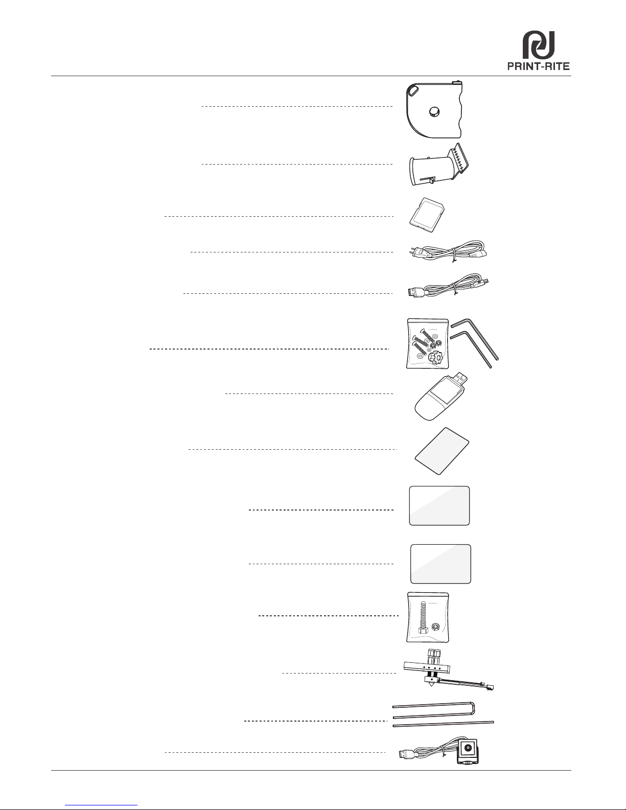
5.2 Accessory Checklist
10
5.4 Unlock Printer Head and Heat Table 11
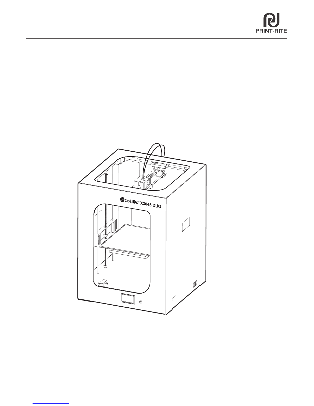
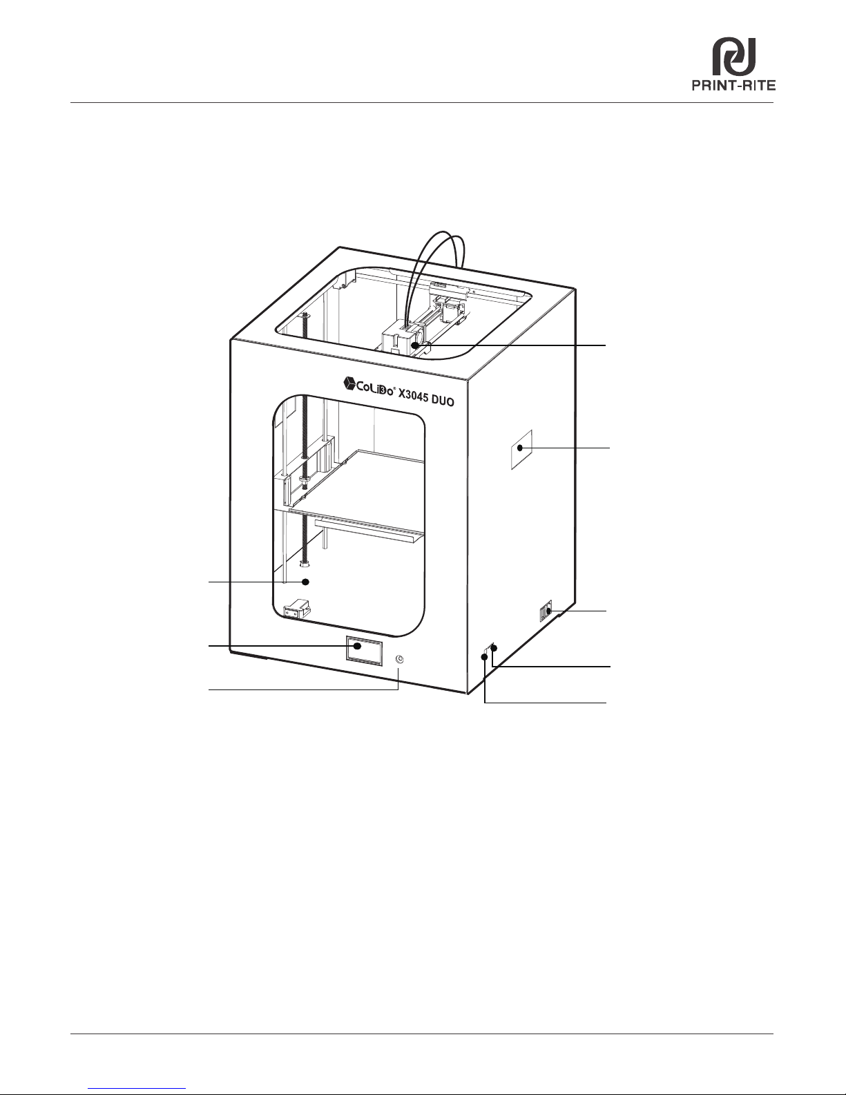
5.3 CoLiDo X3045 Duo 3D Printer Structure Illustration
12~14
5.5 Install Glass Platform
Chapter 3 Specification 06
Chapter 4 Print Principle 07
Chapter 5 Set up CoLiDo Printer
TM
15~175.6 Install Filament
6.2 Calibrate Mode 20~22
23~24
6.1 Main Menu 19
6.3 Nozzle & Filament Test
25~26
6.4 Print test with SD Card
27
6.5 Prepare Menu
28
6.6 Choose Nozzle
31~33
6.8 Color Mixing
Chapter 6 CoLiDo Printer Calibrate and Test
Chapter 8 Maintenance 78
Chapter 7 REPETIER-HOST Setup, Slice and Print
7.1 Install REPETIER-HOST 39~42
7.2 REPETIER-HOST Setup_Single Color/Color Mixing 43~44
7.3 Slice_Single Color/Color Mixing 45~46
Chapter 9 Troubleshoot 79~81
29~30
6.7 Change Filament
7.4 Printing_Single Color
7.5 Printing_Color Mixing 50~51
36~38
6.10 Print from SD Menu
34~35
6.9 Control Menu
47~49
7.6 Repetier-Host Setup_Two Color/Two Material 51
7.7 Slice_Two Color 52~53
7.8 Slice_Two Material 55~57
7.10 Repetier-Host Basic 3D Printing 70
7.11 Repetier-Host Advanced 3D Printing 71~77
185.7 Install camera
7.9 Printing using WIFI communication 58~69