Maico Centro-M User manual

Installation and operating instructions
Flush-mounted exhaust air elements for Centro centralised
ventilation system according to DIN 18017-3
Centro-M
Centro-E
Centro-H
www.maico-ventilatoren.com

Table of contents
2
Table of contents
1 Scope of delivery .................................. 3
2 Specialist installer qualifications ........ 3
3 Intended use.......................................... 3
4 Safety instructions and warnings ....... 3
5 System and product information ........ 3
5.1 Centro centralised ventilation sys-
tem..................................................
3
5.2 Certificates of approval................... 3
5.3 Permitted exhaust air systems ....... 3
5.4 Installation conditions ..................... 3
5.5 Exhaust air elements...................... 4
5.6 Product features ............................. 4
6 Technical data....................................... 4
6.1 Environmental conditions and oper-
ating limits.......................................
4
6.2 Regulations for operation with fire-
places .............................................
4
6.3 Technical data table ....................... 5
6.4 Storage ........................................... 5
7 Mounting preparations......................... 5
8 Installation............................................. 5
8.1 Installation information on flush-
mounted housing............................
5
8.2 Electrical connection....................... 5
8.3 Installation of spiral housing and
upper part of housing......................
5
8.4 Installing the cover.......................... 7
9 Commissioning..................................... 7
10 Operating the unit................................. 7
11 Cleaning, maintenance......................... 8
12 Fault rectification.................................. 8
13 Spare parts ............................................ 9
14 Removing the housing ......................... 10
15 Removal................................................. 10
16 Environmentally responsible dis-
posal ......................................................
10

Preface
3
Preface
Please read the instructions carefully before in-
stalling and using for the first time. Follow the in-
structions. Pass these instructions on to the
owner for safekeeping.
These supplementary instructions are only valid
in combination with the ER UP/Centro main in-
structions, see housing unit. The safety instruc-
tions listed there and the information on non-in-
tended use apply.
1 Scope of delivery
• Exhaust air element, consisting of spiral hous-
ing and cover with G2 filter
• Centro-E with servomotor in spiral housing
• Centro-H with servomotor and H board in spiral
housing
Other components
• Time strip on title page of these instructions
• Installation and operating instructions
2 Specialist installer qualifications
Installation may only be carried out by trained
specialists who have the necessary knowledge
and experience in ventilation engineering. The
unit must be connected in accordance with the
national technical approval.
Only a qualified electrician is permitted to work
on the electrics. You are deemed a qualified elec-
trician if you are familiar with the relevant stand-
ards and guidelines, can competently and safely
connect units to an electrical power supply in line
with the Wiring diagrams and are able to recog-
nise and avoid risks and dangers associated with
electricity on the basis of your technical training
and experience.
3 Intended use
Centro-M/Centro-E/Centro-H exhaust air ele-
ments are intended for use in centralised ventila-
tion units with a common main duct.
The exhaust air elements are used to ventilate in-
terior bathrooms, toilet rooms and open-plan kit-
chens (with exterior windows), storage rooms,
etc.
After completion of the interior building work, the
exhaust air elements are inserted into the flush-
mounted housing units (ER-UPB-, ER-UPD or
ER-UP/G) already installed during the shell con-
struction phase.
Exhaust air elements are only intended for do-
mestic use and similar purposes. No other or ad-
ditional use is intended.
4 Safety instructions and warn-
ings
See ER UP/Centro main instructions for the hous-
ing unit.
5 System and product informa-
tion
5.1 Centro centralised ventilation sys-
tem
A central roof fan or ventilation box extracts the
stale, humid air via the exhaust air elements in-
stalled in bathrooms, toilet rooms and kitchens.
At the same time, outside air flows draught-free
into the apartment(s) via supply air elements. The
Centro pressure controller keeps the air supply
pressure of the central fan constant.
5.2 Certificates of approval
Certificates of approval on request.
5.3 Permitted exhaust air systems
Exhaust air system Centro-M/-
E/-H
Ceiling barrier system yes
System with fire-proof shaft yes
→ For permissible connection cables, specifica-
tions according to approval.
5.4 Installation conditions
If installed in accordance with DIN18017-3,
use is only permitted:
• in central ventilation systems with a common
main duct;
• with an air supply via shaft or duct;
• with permitted connection ducts;
• with unit suitable for the system (Permitted ex-
haust air systems);
• for a flush-mounted installation in the wall or
ceiling with approved flush-mounted housing
unit.
• if correctly installed as per the instructions in
this manual, the ER UP/Centro main instruc-
tions and national technical approval;
• with sufficient space from the wall or ceiling;

6 Technical data
4
• with a fireproof installation shaft for ER-UPB
housings;
• if unit is completely installed;
• with permissible air filters (Permitted exhaust air
systems);
• with the outside air openings stated in the plan-
ning documents;
• Centro-E/Centro-H: pressure controller for the
centralised fan required.
5.5 Exhaust air elements
Centro-M
Manual model. For use in systems with jointly
variable volumetric flows. Fixed air volume setting
by pushing out sealing plugs in each exhaust air
element.
Centro-E
Electric model. With electro-thermal servomotor
for switching between basic and demand-based
ventilation. Fixed air volume setting of the basic
ventilation by pushing out sealing plugs in each
exhaust air element. Demand-based ventilation
automatically via servomotor.
Centro-H
Model with automatic humidity control. Barrier-
free product as the fan switches itself on and off
automatically. With fixed air volume setting of the
basic ventilation by pushing out sealing plugs in
each exhaust air element. Demand-based ventila-
tion automatically or via a switch (for example
light switch).
5.6 Product features
• Fire protection identical with Maico ER single-
room air extraction, see ER UP/Centro main in-
structions.
• No cold smoke barriers required.
• No additional telephony sound absorbers re-
quired.
• It is possible to rotate the cover by ±5° (for
housings which have been fitted at an angle).
• Control circuit board in spiral housing for
Centro-H.
• Centro-H not approved for second room con-
nection.
• The flush-mounted housing has easy to install
snap-in exhaust air elements.
• Quick installation of E and H units thanks to
electrical plug connection in flush-mounted
housing.
• Shaft level difference according to DIN 4109,
tested by IAB Oberursel (The Institute for
Acoustics and Building Physics in Germany).
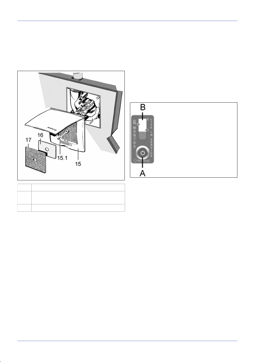
• Cover with exhaust air filter and time strip. Air
filters are to be changed regularly when filter
change is indicated (time strip).
• Trouble-free filter change without tools.
• Centro-M with protection class II. Installation
also permissible with water jets (DIN VDE
0100-701, area 1).
The time strip is visibly attached to a location
of your choice (e.g. next to the cover) and after
the filter change interval has elapsed, it can be
disposed of in the domestic waste. Do not affix
the time strip under the cover. New time strips are
included in the scope of delivery of the exchange
air filter.
6 Technical data
6.1 Environmental conditions and op-
erating limits
• Permissible maximum temperature of air me-
dium + 40 °C.
• The air supply to the home must be set up so
that virtually no air can flow into the living areas
from the kitchen, bathroom or WC.
• Minimum volumetric flow per exhaust air ele-
ment 30 m³/h.
• A room from which the air is to be extracted
must be fitted with a non-closable, free supply
air cross section of at least 150cm², e.g. with
MLK door ventilation grille.
• Centro-E and Centro-H with resistance to inter-
ference according to EN55014-2 – 1000 to
4000 V depending on pulse type and energy
component. When operating with fluorescent
tubes, these values can be exceeded. In this
case, additional interference suppression meas-
ures (L, C or RC modules, protection diodes,
varistors) are required.
6.2 Regulations for operation with
fireplaces
Sufficient supply air intake must be ensured
during operation with air-ventilated fireplaces.
The maximum permitted pressure difference per
residential unit is 4 Pa.
The unit may only be installed in residential units
with air-ventilated fireplaces under the following
conditions:

7 Mounting preparations
5
• the evaluation criteria drawn up by the respons-
ible, regional master chimney sweep are met;
• Parallel operation of air-ventilated fireplaces for
liquid or gaseous fuels and air-extracting equip-
ment can be prevented using safety devices or
• the extraction of exhaust gas from the air-ventil-
ated fireplaces is monitored by special safety
devices. The ventilation system or the fire-
places must be switched off if the equipment is
triggered.
6.3 Technical data table
Rated voltage Centro-
E/Centro-H
230 V
Power frequency
Centro-E/Centro-H
50 Hz/60 Hz
Degree of protection IP X5
Protection class
Centro-E-APB II
Centro-H-APB II
Minimum volumetric
flow
30 m³/h
Air volume 30 / 65 m³/h
Sound pressure level
LWA7
26 to 33 dB(A), depend-
ing on unit model
Weight 0.8 kg
For more technical data → rating plate.
For characteristic curves → www.maico-ventil-
atoren.com
6.4 Storage
Only store unit horizontally in a suitable, dry
room. Ambient temperature – 10 °C to + 60 °C.
Maico accepts no liability for corrosion damage
caused by improper storage, e.g. storage in a
damp environment.
7 Mounting preparations
Suitable mounting material is to be
provided by the customer.
8 Installation
8.1 Installation information on flush-
mounted housing
The installation of flush-mounted housing
and the shut-off device is described in detail in
the ER/Centro main instructions. Be sure to
proceed as described there. Also observe the
requirements in line with the approval.
8.2 Electrical connection
Centro-E and Centro-H
The electrical connection of Centro-E and
Centro-H devices is described in detail in the
ER UP/Centro main instructions. Be sure to
proceed as described there. The electrical con-
nection must be made in accordance with the
wiring diagram.
Centro-E Centro-H
8.3 Installation of spiral housing and
upper part of housing
DANGER Danger to life from electric
shock.
Prior to accessing the connection terminals,
switch off all supply circuits. Switch off mains
fuse, secure against being accidentally switched
back on and position a visible warning sign.

8 Installation
6
1. Press the desired number of sealing plugs out
of the housing.
Centro-M with fixed air volume setting.
Centro-E and Centro-H with fixed air volume
setting for basic ventilation.
11 Spiral housing 12 Electronic circuit
board (control)
13 Housing floor
seal
38 Plaster protect-
ive cover
42 Connection ter-
minal
43 Optional fixing
with screws (to
be provided by
the customer)
44 Locking lever 45 Stud
2. Switch off mains fuse and fit warning sign
3. Remove plaster protective cover and clean
any dirt off the flush-mounted housing.
4. Ensure that the unit type ticked in the housing
box matches the type to be fitted.
5. Check ease of movement of shut-off shutter/
backflow preventer.
When installed, the shut-off shutter/backflow
preventer must close automatically. With ER-
UPD and ER-UPB, this must close automatic-
ally due to the pressure of the inserted yoke
spring (exception – upwards air outlet, see ER
UP/Centro main instructions). With ER-UPD
and ER-UPB ensure that the soldered strut is
inserted correctly, see ER UP/Centro main in-
structions).
6. Check that the housing floor seal is correctly
positioned, then insert properly.
NOTICE Risk of damage if ESD sensitive com-
ponents on the board are touched.
Avoid direct touching of the components or con-
tact surfaces.
NOTICE The noise level will increase if the
housing floor seal is fitted incorrectly. Degree
of protection not guaranteed if housing floor
seal is positioned incorrectly.
The housing floor seal must lie flat and without
any creases in the housing.
7. Check that all screw connections are tight.
8. Check ventilation ducts for dirt and clean if ne-
cessary.
9. Check that connection data matches the tech-
nical data on the unit (rating plate).
NOTICE Function will be impaired if fan insert
is not inserted correctly.
Ensure proper insertion in the locking hooks.
If the fan insert is not firmly seated, screw it to the
housing at the 3 positions shown in the figure
above. Suitable mounting material is to be
provided by the customer.
Note wiring diagrams in box base.
Cables must not prevent the unit from being slid
in.
Lever and stud must
engage.
If they do not, secure
screws through these
holes!
→ Installation information in unit
NOTICE Function will be impaired if spiral
housing is not inserted correctly.
Ensure proper insertion in the 3 fixing points.
10.Slide spiral housing evenly, in parallel, onto
both studs. Ensure that the two locking tabs of
the stud and the locking lever audibly engage
so spiral housing is secure.

9 Commissioning
7
11.Ensure that the spiral housing is correctly en-
gaged. To do this, gently pull and press
against the spiral housing. The spiral housing
must not move in the process. Alternatively,
screw the spiral housing tightly into the hous-
ing → previous figure.
8.4 Installing the cover
15 Cover with central screw [15.1]
16 Regulating plate for second room connec-
tion
17 Filter mat, filter class G2
Installation information
• Cover can be turned up to ± 5° (to provide com-
pensation if housing is inserted at too much of
an angle). If installing on a wall, ensure that the
Maico name is in the bottom right.
• If the housing edge is flush with the plaster, use
central screw, M6 x 16 mm, to secure the
cover.
• With a plaster overshoot of up to 20mm to the
housing edge, use spacing frame DR 60/100
between the wall and cover. The customer
should provide a longer screw (M6 fillister head)
to secure the cover.
• If the housing is plastered in too deep, com-
pensate for this with a two-part wall frame ER-
MR (can be adjusted between 50...100mm).
This prevents air from being drawn in from the
shaft. Use the supplied screw to fix the cover.
1. Fold up cover at the recessed grip, place on
the housing and secure with the central screw.
2. If necessary, first fit a spacing or wall frame.
3. With second room extraction, insert regulating
plate below locking tabs at the side on the in-
take grille of the cover, insert filter mat.
4. Lock cover. The lock must engage audibly.
5. Switch on mains fuse, remove warning sign.
6. Undertake initial commissioning and function
test.
7. Affix time strip (supplied with the cover) and
push the activation button [A] all the way. In-
stallation location of time strip, e.g. near the
cover.
The red dye in the interior of the
bar [B] is released. The
bar indicator first fills
slightly. Within the
next 6 months, the bar
indicator [B] will rise to the
upper edge (indicator value 6).
9 Commissioning
1. Switch on mains fuse and remove warning
sign.
2. Run function test. To do this, switch unit on
and off, observe delay times (for control mod-
els Controls (circuit board types)).
3. Check that the unit is running smoothly. It is
also important that the air can flow un-
hindered.
4. Switch off unit.
10 Operating the unit
Centro-M
No operation of the standalone unit is possible. It
is used in systems with a jointly variable volumet-
ric flow. In combination with a timer and a step
transformer, the volumetric air flow of the entire
air extraction system can be controlled centrally.
Centro-E
Exhaust air element with servomotor. For use in
systems with variable volumetric flows for indi-
vidual apartments. Basic and demand-based
ventilation can be switched on and off via a light

11 Cleaning, maintenance
8
switch. Demand-based ventilation after start delay
of approx. 1 minute. Overrun time after switching
off, approx. 3 minutes.
Control of the volumetric air flows within the vent-
ilation system with Centro pressure controller.
Speed control of the central fan automatically.
Centro-H
Exhaust air element with servomotor and humidity
control. For use in systems with variable volumet-
ric flow for individual apartments. Standard opera-
tion – basic ventilation, automatic switchover to
full load if required (switch-on/switch-off point ad-
justable). Demand-based ventilation can also be
switched on by light switch.
Control of the air volume flows within the ventila-
tion system by pressure or speed control of the
central fan.
Once the exhaust air element has been installed,
the unit regulates to the current room humidity
(relative humidity). This humidity value is saved
as the first reference value. The reference value
does not have to be specified manually. If the
room humidity rises by 7 % within 2 minutes, the
exhaust air element switches to full load operation
(demand-based ventilation). If the relative humid-
ity falls below the reference value during opera-
tion, the newly established reference value is
saved. The exhaust air element then automatic-
ally switches back to base load operation or to
Off. Demand-based ventilation automatically or
via a switch (e.g. light switch). After manual
switch-on (light switch) the exhaust air element
runs with a start delay of approx. 1 minute with
demand-based ventilation (full load). After manual
switch-off, the exhaust air element continues to
run in nominal load operation with an overrun
time of 15 minutes (valve closing time approx. 2 -
3 minutes).
When switch is open, the exhaust air ele-
ment can start up automatically as a result of
high room humidity.
11 Cleaning, maintenance
The unit is practically maintenance-free. The air
filter must be replaced every 3 to 6 months, de-
pending on the degree of soiling.
Replacement filter mats ZF 60/100 5-pack,
filter class G2 according to EN 779, art. no.
0093.0331 + filter change indicator (time strip)
For filter change and cleaning → ER UP/Centro
main instructions.
12 Fault rectification
Fault finding and repairs only permissible
when carried out by qualified electricians.
DANGER Danger to life from electric
shock.
Prior to accessing the connection terminals,
switch off all supply circuits. Switch off mains
fuse, secure against being accidentally switched
back on and position a visible warning sign.

13 Spare parts
9
Fault Cause → Measure
Fan performance inad-
equate.
Dirty filter. → Replace
filter.
Locking hook not en-
gaged. → Engage fan
insert correctly.
Incorrect duct diameter.
→ Check diameter of
the main duct.
Supply air cross section
is too small. → Increase
the supply air cross
section.
Spiral housing too loud. Dirty filter. → Replace
filter.
Fan insert incorrectly in-
stalled. → Insert fan in-
sert correctly in accord-
ance with these instruc-
tions.
The main duct is under-
sized. → Re-calculate
pressure losses.
H model does not
switch from base load
to full load operation
despite there being hu-
midity in the room.
No rapid increase in hu-
midity (7% in 2 minutes)
took place.
H model no longer
switches back to base
load operation or off
even after a long period
in full load operation.
The level has not yet
fallen below reference
value. After 1 h, the
valve automatically
switches from full load
operation to base load
operation after an over-
run time of 15 minutes
and resets the refer-
ence value.
Additional consumers
connected to terminal 4.
Damage to the unit if
connected incorrectly.
Do not connect addi-
tional consumers to ter-
minal 4.
The unit may only be
connected according to
the wiring diagrams
(Wiring diagrams).
If the fault persists or reoccurs: Disconnect
the unit completely from the power supply. Let a
qualified electrician determine the cause of the
fault and eliminate it. If you have any question re-
lating to troubleshooting: Service: +49 7720 6940.
13 Spare parts
Spare parts may only be sourced from and
fitted by a specialist installer.
Designation Article no.
Spiral housing, cpl.
Centro-M
Centro-E
Centro-H
E084.0182.0000
E084.0183.0000
E084.0187.0000
Cover ABD ER 60/100/
Centro
E059.1017.9000
Filter mat ZF 60/100: 5
pieces, filter class G2
according to EN 779
with filter change indic-
ator (time strip)
0093.0331
In case of questions, please contact:
Maico Elektroapparate-Fabrik GmbH
Steinbeisstraße 20
78056 Villingen-Schwenningen, Deutschland
Tel. +49 7720 694 445
Fax +49 7720 694 175
E-mail: [email protected]
Spare parts can be ordered at
www.shop.maico-ventilatoren.com.

14 Removing the housing
10
14 Removing the housing
4 Fan insert 36 Locking tabs
37 Locking lever 38 Locking tabs
1. Switch off mains fuse, secure and fit warning
sign.
2. Remove cover and upper part of housing.
3. Press locking lever slightly to the left (→ arrow
I), release and raise the fan insert slightly.
4. Press together locking tabs of stud and raise
fan insert slightly.
5. Press together locking tabs of stud and evenly
pull entire fan insert out of lower part of hous-
ing in parallel (→ arrows I - III).
6. Installation is carried out in reverse order.
15 Removal
Dismantling may only be undertaken by a
qualified electrician.
DANGER Danger to life from electric
shock.
Prior to accessing the connection terminals,
switch off all supply circuits. Switch off mains
fuse, secure against being accidentally switched
back on and position a visible warning sign.
1. Remove spiral housing.
2. Remove all cables.
3. Remove lower part of housing from the wall.
16 Environmentally responsible
disposal
The ventilation unit and the packaging contain
parts that can be recycled, and should not end up
in the domestic waste.
Dispose of the packaging material in an environ-
mentally-friendly way, in compliance with the reg-
ulations valid in the country where you are.
Dispose of the air filter in an environmentally-
friendly way, in compliance with the regulations
valid in the country where you are.
At the end of its service life, dispose of the unit in
an environmentally-friendly way, in compliance
with the regulations valid in the country where you
are.

Notes

Maico Elektroapparate-Fabrik GmbH
Steinbeisstr. 20
78056 Villingen-Schwenningen
Deutschland
Service +49 7720 6940
D07.21_EN_DSW-AV
This manual suits for next models
5
Table of contents
Other Maico Fan manuals

Maico
Maico ECA piano STANDARD Service manual

Maico
Maico EZD 30 B Series Service manual

Maico
Maico ER-A Service manual

Maico
Maico AS 20 User manual

Maico
Maico DAS 71/4 Service manual

Maico
Maico EZQ B Series User manual

Maico
Maico ECA 100 ipro VZC Service manual

Maico
Maico ALD 125 Service manual

Maico
Maico ECA piano STANDARD Service manual

Maico
Maico DZQ B Series User manual

Maico
Maico PP 45 O User manual

Maico
Maico ER EC RF17 User manual

Maico
Maico GRD 22 Service manual

Maico
Maico FE100/1 AP User manual

Maico
Maico ER GH User manual

Maico
Maico AE 10/1 User manual

Maico
Maico EVR 31 Service manual

Maico
Maico EVN 22 User manual

Maico
Maico WR 410 User manual

Maico
Maico HDR 12 Service manual