Commodore Amiga A500 User manual

Diagnostic Kit
User’s Manual
Cr Commodore


A2000
Diagnostic Kit
Uset^s Manual
Commodore

This document is created using the Professional Page program on the Amiga. Pages
were proofed from laser printer and the final film output was produced from a
Linotronic 300 high resolution PostScript typesetter.
First Printing in ctober 1988.
© 1988 Commodore Buromaschinen GmbH. All rights reserved.
This document may not, in whole or in part, be copied, photocopied, reproduced,
translated, or reduced to any electronic medium or machine readable form, without
prior consent, in writing, from Commodore Buromaschinen GmbH, West-Germany.
Commodore and the Commodore Logo are registered trademarks of Commodore
Electronics Limited. Amiga is a registered trademark and Amiga 2000, Amiga 500,
AmigaD S, Kickstart, Workbench and CLI are trademarks of Commodore-Amiga,
Inc. All further products mentioned in this document are trademarks of their
respective owners.
Commodore makes no warranties or guaranties, either expressed, or implied, with
respect to the products described in this document, their functionality, compatibility or
availability. Further, Commodore assumes no responsibilty or liability for statements
or representations made by itself or by a third party vendors or in the publications
reproduced herein. IN N EVENT WILL C MM D RE BE LIABLE F R
DIRECT, INDIRECT, INCIDENTAL, R C NSEQUENTIAL DAMAGES
RESULTING FR M ANY CLAIM ARISING UT F THE REPRESENTATI NS
MADE HEREIN, EVEN IF IT HAS BEEN ADVISED F THE P SSIBILITIES F
SUCH DAMAGES.
Information in this document is subject to change without notice and does not
represent a commitment on the part of Commdore Business Machines.
Part No.: 380 568-01 B
Printed in West-Germany.

Table of contents
Introduction 2
How to use 3
Connecting the Amiga Diagnostic Box 4
A2000: Inserting the Amiga Diagnostic Modu e 5
A2000: Connecting Power 6
A500: Inserting the Amiga Diagnostic Modu e 7
A500: Connecting Power 7
How the Test Works 8
Differences between ROM- and Disk-Test 9
Connecting a Termina 9
Detai ed Testdiscription 10
Error Code Tab e 14
1

C MM D RE AMIGA 500 / 2000 DIAGN STIC (PAD
First read this manual completly.
This package inc udes everything to perform an AMIGA diagnostic test, exept the
C64 PSU and A501 needed to test an AMIGA 500. This test checks a RAM, every
port, the four sound channe s and video of the AMIGA 500 and AMIGA 2000, but it
does not check the expansion-s ots of the AMIGA 2000.
Note: This test is for service only!
Make sure that you have got a of these parts:
CONTENTS:
1 AMIGA DIAGNOSTIC BOX
1 AMIGA DIAGNOSTIC MODULE
9 AMIGA DIAGNOSTIC CABLES
1 AMIGA DIAGNOSTIC DISK
1 AMIGA DIAGNOSTIC USER GUIDE
1 DISK "PC TERMINAL EMULATION"
Warning: Before connecting or disconnecting anything to / from an AMIGA
please make sure that the AMIGA system is switched off.
2

How to use the AMIGA DIAGN STIC KIT
You can run this test either from diskette or from ROM, depending on what you
prefere: If you do not want to open the AMIGA 2000, use the AMIGA DIAGNOSTIC
DISK ( A.D. DISK ), but then a part of the CHIP-RAM can not be tested.
The ROM-based test resides comp et y in the AMIGA DIAGNOSTIC MODULE
(A.D. MODULE), so the test wi start even if the machine is fau ty. Additiona y this
test checks a CHIP- and FAST-RAM.
To run the ROM-based test:
- A500 on y: insert A501
- connect the AMIGA DIAGNOSTIC (A. D.)BOX with the AMIGA
- optiona : connect a termina to the A. D. BOX
- insert the A. D. MODULE
- connect power to both A. D. BOX and AMIGA
- set the switch on the eft side of the A. D. BOX to A2000 or A500
- turn power on
To run the disk-based test:
- A500 on y: insert A501
- connect the AMIGA DIAGNOSTIC (A. D.)BOX with the AMIGA
- optiona : connect a termina to the A. D. BOX
- connect power to both A. D. BOX and AMIGA
- set the switch on the eft side of the A. D. BOX to A2000 or A500
- turn power on
- insert the A. D. DISK at Workbench-prompt
For detai ed information see chapters be ow.
To run the test, you have to connect the AMIGA DIAGNOSTIC BOX (A.D. BOX) to
a power supp y. You may use a C64 PSU ( testing an A500) or you can connect it to
the FDD-PSU-Connector of an A2000 power supp y (see chapters be ow).
The A.D. B X does not supply the AMIGA-PCB with power nor does the
AMIGA-PCB supply the A.D. B X.
Press the RESET BUTTON on the A.D. BOX, if the test does not start correct y.
The test finishes with an a ternate disp ay of two test screens on the monitor and
running numbers disp ayed on the LEDs at the A.D. BOX.
3

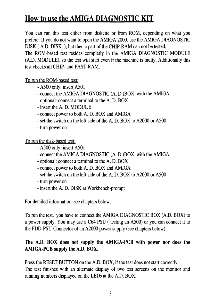
When an error occurs, a two digit hex number is disp ayed on the LED disp ay on the
A.D. BOX. This error code indicates which test fai ed. You find a comp ete ist of a
error codes in the AMIGA DIAGNOSTIC ERROR TABLE.
Connecting the AMIGA DIAGN STIC B X
You have to insta seven cab es between the A.D. BOX and the A500 / A2000. You
can distinguish these cab es by the connectors of the cab es:
1. ne cable for the internal Disk Drive:
This cabe has a 35 pin SUB-MINI-D (SMD) ma e and a 35 pin card edge connector.
P ug the 35 pin SMD into the connector abe ed "Disk Drive intern" and connect the
other end to the interna drive connector.
2/3. Two identical cables for Serial and Parallel Port
These cab es have both a 25 pin SMD ma e and 25 pin SMD fema e connector.
P ug the first 25 pin SMD ma e into the A.D. BOX-connector abe ed "Seria Port",
the other end into the seria port of the AMIGA ( short cab e).
P ug the second 25 pin SMD fema e into the A.D. BOX-connector abe ed "Para e
Port", the other end into the para e port of the AMIGA ( ong cab e).
4. ne cable for the external Disk Drive:
This cab e has a 23 pin SMD fema e and a 25 pin SMD ma e connector.
P ug the 25 pin SMD (ma e) into the A.D. BOX-connector abe ed "Disk Drive
extern", the other into the externa disk drive connector of the AMIGA.
5. ne cable for the Keyboard:
A2000: use the cab e with 9pin SMD fema e and 5pin DIN connector.
A500: use the cab e with 9pin SMD fema e and 5pin f at connector.
P ug the 9 pin SMD (ma e) into the A.D. BOX-connector abe ed "Keyboard", the
other side into the A500 / A2000 keyboard connector.
6/7. Two cables for both Mouse/Joystick-Ports
These cab es have 9 pin SMD fema e connectors on both sides.
P ug one of the SMDs into the A.D. BOX-connector abe ed "Mouse / Joystick 1", the
other end into the port where norma y the mouse is connected.
Connect the other mouse/joystick port with the other cab e to the A.D.
BOX-connector abe ed "Mouse / Joystick 2".
4

A2000: Inserting the A. D. M DULE
If you want to run the ROM based diagnostic, you have to insert the AMIGA
DIAGNOSTIC MODULE (A.D. MODULE).
Be sure to turn off a power, and open the Amiga 2000.
Insert the A. D. MODULE into the MMU connector next to the CPU in the same way
you insert any other AMIGA expansion cards ( abe ed side facing the PSU-subchassis,
see picture be ow).
Picture 1: How to insert the AMIGA DIAGNOSTIC MODULE into an A2000
5

A2000; Connecting Power
To run the test, you have to connect the A.D.BOX with a power supp y: connect the
A. D. BOX to the FDD-PSU-connector of the A2000 PSU.
NOTE: the A2000 PSU needs at east 30% of its nomina oad to work correct y, so
connect the mainboard to the same PSU.
Make sure that the power supp y is switched off when you connect it to the A.D.BOX.
Both, AMIGA and power supp y, have to be connected to your oca net as we . The
A.D.BOX. does not supp y the AMIGA with power nor does the AMIGA supp y
the A.D.BOX.
Picture 2: A2000 with AMIGA DIAGNOSTIC KIT connected
6

A500: Inserting the A.D.Module
Remove the expansion port pane and insert the AMIGA DIAGNOSTIC MODULE
(see picture be ow).
Picture 3: A500 with AMIGA DIAGNOSTIC KIT connected
A500: Connecting power
To run the test, you have to connect the A.D. BOX to a C64-PSU and the A500 to its
own power supp y.
Make sure that the power supp vs are switched off when you connect them, and that
they have the correct vo tage rating!
NOTE: If you switch on the AMIGA seperat y, no damage wi occur. If the test
does not work proper y, try the reset button at the rear of the A.D. BOX.
To avoid anv troub e, switch on the AMIGA and the A.D. BOX together with an
extra nower switch.
7

How the Test Works
Once the test is started, severa numbers are disp ayed on the two digit
LED-disp ay on the A.D.BOX indicating which part of the test is executed.
This messages wi be disp ayed on the termina (ROM based version):
HIMAX 1.2 -- 3-Feb-1987 - 16:27:30 This is the identification
Commodore AMIGA Diagnostic WRAPAROUND
Test
Copyright (C) 1985, Commodore Amiga, Inc.
A rights reserved.
** For use with Version 11 Boot ROMs **
of this test.
?EJ1** NOTE: An Interna Disk Drive not found! **
EJI: this idicates, that the
keyboard test is passed.
NOTE: An Interna Disk
Drive...
this means that no FDD
is connected and the
FDD interface is tested.
Note *** date set to : 87 1 1 10:0:0 Now you shou d hear the
sound test
Found RAM at COOOOO the additiona RAM at
COOOOO was found and
tested.
++ END of HIMAX (1.2 - 3-Feb-1987 - 16:27:30) This the end of the test.
At the end of the test two pictures are a ternative y disp ayed on the monitor: The
first one shows a HAM-demo, changing from b ue / green to red/ye ow, the nine
sprites ( the itt e boxes in a row ) and a red box with two, on y one pixe wide
point.
The second picture shows a test picture as you may know it from TV. At this time
there are numbers scro ing on the LED-disp ay on the A.D.BOX. A this indicates
that the test was successfu y finished.
8

Differences between R M- and the Disk-Test
A though both versions of the test are basica y the same, there are some minor
differences:
The disk test reports every test on the termina , the ROM test does not.
There are three additiona messages disp ayed because the FDD is connected:
** NOTE: An Interna Disk Drive has been found! **
** NOTE: Interna Disk Test SKIPPED-diagnostic cab e not connected **
Test #60 - Test EXTERNAL Disk Contro Lines
** NOTE: An Interna Disk is Connected
Note: These messages do not mean that an error occured!
They only indicate, that all tests of the internal FDD interface are not executed.
To oad this test from disk, a ot of system functions are needed: appr. 40k of
CHIP-RAM, DMA (AGNUS), PAULA, CIAs and more. But this test checks a ports
and system functions without opening the AMIGA 2000.
Connecting a Terminal
You may connect a termina at the rear of the A.D. BOX with the RS232 cab e
inc udeL For examp e connect a PC running the termina emu ation program, which
is on the 5 1/4" disk.
Protoco : 9600 baud, 8 bit, 1 stop bit, no parity
On this termina a messages wi be disp ayed. Norma y the test stops when an error
occurs. By pressing SPACE-BAR the test wi continue, by pressing RETURN the
test-step wi be repeated.
9

Detailed Testdiscription:
This chapter gives a short overview of what the test does.
The Test starts with setting up system: initia izing the ports, mounting the
exception-vectors etc.
Then the tests are performed.
If an error occurs, an errorcode is disp ayed on the LED-panne on the
AMIGA-DIAGNOSTIC-BOX and a more detai ed message is put to the termina .
Then the test waits for your input from the termina :
if you press the space bar, the test wi be continued,
if you press return, this test-step wi be repeated.
There is a possibi ity to get into a he p- / debug-menu. This is not ready yet (may be this
wi never be) and therefor not documented.
Test# - Read ast ROM ocation
Test #2 - Set CBM as input, ck data and c ocks
Test #3 - DRDY and ACK test
Test #4 - Check the CBM Seria Data Line
Test #5 - Check RTS-CTS bit set oop
Test #6 - Check RTS-CTS bit c ear oop
Test #7 - Check DTR-DSR bit set oop
Test #8 - Check DTR-DSR bit c ear oop
Verify HIMAX:
check test equipment and
used ports
Test #9 - Ro a zero through the para e port
Test #A - Ro a one through the para e port
Test #B
Test #C
Test #D
Test #E
Test #F
W/R a "?" character via the seria connection
W/R a ME" character via the seria connection
W/R a "J" character via the seria connection
W/R a "1" character via the seria connection
Keyboard Communications Test
Test the
Serial Port
and the Keyboard
10

Test #10-
Test #11-
Test #20 -
Test #21-
Test #22 -
Test #23 -
Test #24 -
Test #25-
Test #26 -
Test #27 -
Test #28 -
Test #29 -
Test #2A •
Test #2A •
Test #2B -
Test #2C -
Test #2D ■
Test #2F -
Test #30-
Test#31 -
Test #32 -
Test #33 -
Test #34 -
Test #35 -
Test #36 -
Test #37 -
Test #38 -
Test #39 -
Test #3A ■
Test #3B -
Test #3C -
Test #47-
"SEL" and "CD"
"SEL" is input, "CD" is output
Resets LOW test
Disk Port
Modem Port
Resets HIGH Test
Disk Port
Modem Port
SET Joystick Fire Lines
Check Fire Lines as Outputs
Fire 1
FireO
Check Fire Lines as inputs
Fire 0 ow, Fire 1 ow
Fire 0 high, Fire 1 ow
Fire 0 ow, Fire 1 high
Fire 0 high, Fire 1 high
Check for Cab e of Interna Disk
+5V Keyboard
+5V Seria Port
+5V Joystick 1 Port
+5 V Joystick 0 Port
+5 V Disk Port
Keyboard
Interna Disk Ground
Externa Disk
Seria Port (pin 7)
Seria Port (pin 1)
Joystick 1
Joystick 0
Externa Disk +12V
Joystick Lines
Test Handshake of Par.-Port
Test Reset Signals
Test Joystick Ports
Test +5V
Test Ground Connections
Test+12V Ext. Disk
Test Joystick Port
11

Test #50 -
Test #51 -
Test #52-
Test #53 -
Test #54-
Test #55 -
Test #56 -
Test #57 -
Test #58 -
Test #59 -
Test #5A
Test #5B •
Test #5C •
Test #5D
Test #5E -
Test #5F -
Test #60 -
Test #64-
Test #6A
Test #6F
Test #72
Test #76
Test #6B
Test #6B
Test #77
Set a Pot ines to output), Verify a ow
Togg e Pot[X] Portf ], Verify ine goes Hi
Togg e Pot[Y] Port[ ], Verify ine goes Hi
Togg e Pot[X] Port[0], Verify ine goes Hi
Togg e Pot[Y] Port[0], Verify ine goes Hi
Set a Pot ines to output, Verify a High
Togg e Pot[X] Port[ ], Verify ine goes Lo
Togg e Pot[Y] Port[ ], Verify ine goes Lo
Togg e Pot[X] Port[0], Verify ine goes Lo
Togg e Pot[Y] Port[0], Verify ine goes Lo
Set up to Begin testing the Pots as inputs
Pot Input oad testing
oad 1
oad 2
oad 3
oad 4
Test POT-Port
SEL1, SEL3B, DIRB, STEPB
DKWEB, SIDEB, SEL2B, MTRXD
INDEX Test Externa Disk Contro
- Disk GROUND, SIDEB, DKWEB,
STEPB, DIRB, MTROD, SELOB,
MTROD, LED, MTRON
INUSE, drivese ect, motoroff
Test Interna Disk Contro
CHNG, WPRO, TKO, RDY
INDEX
Light pen — “
AGNUS First Test of AGNUS
! Lightpentest is not reiiabie!
Force Reset Test with "NARROW" pu se,
then KBRESET Test the
RESET-Lines
12

Test #80 - ROM Checksum Checking
Test #88 - Check "ROM" ock of RAM
Test The
Kickstart-R M
Test #89 - Check The Four Audio Channe s, and Audio DMA
Test #90 - Custom Chip Register Testing, C ear ADKCON
Test #91 - ADKCON set and c ear bits oon
Test #92 - CLXDAT c ear
Test #93 - DMACON[R] register check
Test #94 - INTREQ register check
Test of
Custom-Ckip-Registers
Test #95 - INTENA register check
Test #E0 - Sing e b itfi
Test #96 - JOYSTICK register check
Test #97 - JOYSTICK register check
Test #98 - JOYSTICK register check
Test #99 - JOYSTICK register check
Test #96 - Rea Time C ock test #1
Test #97 - Rea Time C ock test #2
Test #98 - Rea Time C ock test #3
Test of
Clock-Chip
Test #F9 - Test of C ockchip
Test#F0- TestChip-RAM
Test #F1 - MirrorTest of CHIP-RAM
Test of
Chip- & Fast-RAM
Test #78 - RAS-/CAS-Test
Test#F2- Test of ChipRam
Test #F3 - Test of expansion
Test #E1 - bui d up picture
Test #E2 - bui d up picture
Test #E3 - bui d up picture
Build-up
Finai Pictures
&
END F HIMAX
13

Amiga Diagnostic Error Code Table
********* 01. Qp.
1 Word s/b: % x, was: $0XXXX
2 CBM c ock fai ure
2 CBM c ock fai ure
2 FF - CBM data fai ure, DO: $0XXXX
2 CBM c ock fai ure
2 00 - CBM data fai ure, DO: $0XXXX
3 DRDY or ACK fai ed
4 C ock fai ure of CBM Seria Data(00) Line
4 Data fai ure of CBM:
4 C ock Fai ure of CBM Seria Data(FF) Line
4 FF Data Fai ure of CBM: $0XXXX
5 CTS was NOT SET!
6 CTS NOT CLEARED!
7 DSR NOT SET!
8 DSR NOT CLEARED!
9 Ro ing a zero fai ed (d0=$0XXXX d2=$0XXXX)
a Ro ing a one fai ed (d0=$0XXXX, d2=$0XXXX)
b "?" not found!
c "E" not found!
d "J" not found!
e "1" not found!
f seria port bit #3 not c eared!
f s/b $FF, was: $0XXXX
f s/b $F0, was: SOXXXX
f s/b $0F, was: SOXXXX
f s/b $AA, was: SOXXXX
f s/b $55, was: SOXXXX
f s/b $00, was: SOXXXX
**** io - IF:
10 "SEL" was hi
10 "CD" was o
10 "SEL" was o
10 "CD" was hi
11 "CD" was hi
11 "CD" is o
14

**** 20-2F:
20 Para e Port RESET ine HIGH
21 Disk Port RESET HIGH
22 Modem Port RESET HIGH
23 Para e Port RESET ow
24 Disk Port RESET was ow
25 Modem Port RESET was ow
26 Joystick Fire Lines fai ed to SET as output!
27 Fire Lines not high
28 Fire 1 is high
29 Fire 0 is high
2a Fire 1 is high
2a Fire 0 is high
2b Fire 1 is Low
2b Fire 0 is High
2c Fire 0 is high
2c Fire 1 is ow
2d Fire 1 is ow
2d Fire 0 is ow
2F Diagnostic Cab e not connected
**** 30-3F:
30 Keyboard +5
31 Seria Port+5
32 JoyStickf ] +5
33 JoyStick[0] +5
34 Disk Drive +5 vo ts
35 KeyBoard Ground
36 Interna Disk Ground
37 Externa Disk Ground
38 Seria Port Ground (pin 7)
39 Seria Port Ground (pin 1)
3a JoyStickf ] Ground
3b JoyStick[0] Ground
3c Externa Disk Drive +12 Not Present
15

**** 40-4F:
40 This error (RESET) was caused by a short circuit!
40 Joystick +5 high
45 Joystick +5 Low
47 JoyStick[0]
47 JoyStick[ ]
**** 50-5F:
50 One of the pot ines fai ed to go ow!
51 Pot[X] Port[ ] pot ine fai ed to go High!
52 Pot[Y] Portf ] pot ine fai ed to go High!
53 Pot[X] Port[0] pot ine fai ed to go High!
54 Pot[Y] Port[0] pot ine fai ed to go High!
55 One of the pot ines fai ed to go ow!
56 Pot[X] Port[ ] pot ine fai ed to go Lo!
57 Pot[Y] Portf ] pot ine fai ed to go Lo!
58 PotfX] PortfO] pot ine fai ed to go Lo!
59 PotfY] PortfO] pot ine fai ed to go Lo!
5a shou d NEVER get here, insta ed for symmetry!
**** 60-6F:
6b (A) _vposr did not atch!, found: OxXXXX, then: OxXXXX
6b (B) Agnus FAULT! Line found s/b: OxXXXX, was: OxXXXX
60 /SEL1B is ow
60 /SEL1B is high
60 /SEL3B is ow
60 /SEL3B is high
60 DIRB is ow
60 DIRB is high
60 /STEPB is ow
60 /STEPB is high
60 /DKWEB is ow
60 /DKWEB is high
60 /SIDEB is ow
60 /SIDEB is high
16
Other manuals for Amiga A500
2
This manual suits for next models
1
Table of contents