manuals.online logo
Brands
  1. Home
  2. •
  3. Brands
  4. •
  5. CommScope
  6. •
  7. Antenna
  8. •
  9. CommScope DB224 User manual

CommScope DB224 User manual

PRODUCT DESCRIPTION
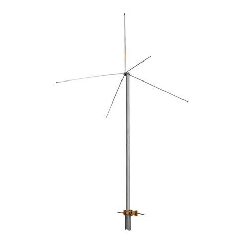
The DB224 is a heavy duty, light weight, high gain antenna.
It is suitable for mounting to the top or on the side of a tower.
Clamps for top mounting are supplied with the antenna; an
additional side mount kit (DB5001) must be ordered for side
mounting.
The antenna is a four stack collinear array designed to provide
high gain, broad bandwidth and minimum pattern distortion.
A binary cable harness is used to ensure equal inphase
power distribution to all radiating elements.
ELECTRICAL DESIGN
OPTIONAL RADIATION PATTERN
The DB224 can be used as an omnidirectional antenna
having a gain of 6 dBd or as an elliptical pattern antenna
having a maximum gain of 9 dBd. An omni pattern is
achieved when the four dipole elements are spaced evenly,
every 90° around the mast (Figures 1 and 2). An elliptical
pattern is obtained when all four dipole elements are positioned
in a line (collinear) along the mast. When top mounted, the
omni and elliptical models provide radiation patterns as shown
in Figure 3. When side mounted, the two models provide
significantly different radiation patterns (see SIDE MOUNTING
and Figure 4). The antenna can be changed in the field from
one pattern to the other using ordinary hand tools.
Figure 2. Top View Dipole Alignment
(continued on page 2)
Wear shoes with rubber soles and heels.
Wear protective clothingincluding a long-
sleeved shirt and rubber gloves.
Do not install near power lines. Power lines,
telephone lines, and guy wires look the same.
Assume any wire or line can electrocute you.
Do not install on a wet or windy day or
when lightning or thunder is in the area.
Do not use metal ladder.
Figure 1. Dipole Alignment
SAFETY NOTICE
The installation, maintenance, or removal of an antenna
requires qualified, experienced personnel. CommScope
installation instructions are written for such installation
personnel. Antenna systems should be inspected once a
year by qualified personnel to verify proper installation,
maintenance, and condition of equipment.
CommScope disclaims any liability or responsibility for the
results of improper or unsafe installation practices.
It is recommended that transmit power be turned off
when the field installation is performed. Follow all
applicable safety precautions as shown on this page.
Broad Band Gain Antenna
DB224
095008-000 Revision R, July 2016
Page 1 of 4
www.commscope.com
© 2016 CommScope, Inc. All rights reserved.
Visit our website at www.commscope.com or contact your local CommScope representative or BusinessPartner for more information.
All trademarks identified by ® or ™ are registered trademarks or trademarks, respectively, of CommScope, Inc. 095008-000 P (07/16)
(Continued from page 1)
TWO PIECE MAST
For ease of handling and to facilitate shipment, the mast is
made in two sections. Assembly of the sections is quite simple
and requires only the use of ordinary hand tools. The unique
center splice assures proper alignment.
LIGHTNING PROTECTION
The aluminum mast with a pointed cap provides a positive
low resistance discharge path to the tower or ground system,
thus affording superior protection against lightning damage.
All radiators are operated at DC ground to provide further
protection against lightning and static buildup.
DUAL ANTENNAS
Dual antenna models are available which include two inde-
pendent antennas on a common mast, each with a separate
feed line terminated at the bottom of the mast. One antenna
is isolated from the other by 30 dB. Model DB224S-( ) con-
sists of two omnidirectional antennas, each having a gain of
3 dBd.
SIDE MOUNTING
When the DB224-( ) and DB224E-( ) antennas are mounted
to the side of a tower the horizontal radiation pattern neces-
sarily becomes distorted. The patterns shown below indicate
the typical pattern shape of the antenna side mounted
on a tower with an 18" to 24" face using the DB5001 Side
Mount Kit.
The DB5001 Side Mount Kit positions the antenna approxi-
mately 18" from the tower and consists of an upper sway
brace, lower bracket (both galvanized) and the necessary
hardware for attaching the bracket to round tower members
up to 3" OD, or angular members up to 2" on a side. Other
size clamps can be supplied on special order.
Figure 3. Radiation Patterns for Top Mounted
DB224-( ) and DB224E-( ) Antennas.
Figure 4. Radiation Patterns
(continued on page 3)
095008-000
Page 2 of 4
www.commscope.com
© 2016 CommScope, Inc. All rights reserved.
Visit our website at www.commscope.com or contact your local CommScope representative or BusinessPartner for more information.
All trademarks identified by ® or ™ are registered trademarks or trademarks, respectively, of CommScope, Inc. 095008-000 P (07/16)
(Continued from page 2)
INSTALLATION PROCEDURE
After removing the antenna from the shipping box, in-
1.
spect it to be sure all parts are on hand and that there is
no physical damage.
2. Inspect the antenna feed assembly output connector to
determine that it mates with the end of your station trans-
mission line. Do not remove any connectors or cables
from the antenna feed assembly since they are all a
part of the antenna.
3. Verify that the frequency to which the antenna has been
tuned is the frequency on which your radio system is to
operate.
4. Slip the mast sections together and position the bands
as shown in Figure 5. Tighten the bands securely; the
recommended tightening torque is 45-60 in-lbs. Then,
join the connectors, making the connections snug, but
do not apply heavy force with pliers. Carefully wrap
Vapor-Wrap
®
around the connection to seal out moisture
problems. Secure the connectors to the mast with
several wraps of tape (see Figure 5).
5. Attach the furnished DB365 mounting clamps to the
bottom of the antenna mast at the designated locations.
Mount the antenna on the tower with the bottom dipole
above and facing away from the tower.
6. A check of the antenna VSWR as measured at the antenna
is recommended at this point. Note this measurement
carefully, and record it for future reference.
7. After checking the VSWR at the antenna, connect the
station transmission line to the antenna; make the con-
nection snug, but do not apply heavy force with pliers.
To avoid moisture problems, carefully wrap Vapor-Wrap
®
around the connection, smoothing it into the cracks and
over the outer jackets of the transmission line. Failure
to waterproof the cable connection can result in improper
operation of your antenna. Properly secure the feeder
cable and antenna transmission line to the tower in the
best position to avoid physical damage to the cable.
8. After the antenna and transmission line installation has
been completed, a careful check should be made to
ensure that:
• All mechanical connections have been securely made.
• The antenna is mounted on the proper leg of the tower
with sufficient physical clearance.
• All connections have been carefully wrapped with
Vapor-Wrap
®
to prevent moisture problems.
Figure 5. Joining the Mast Sections
095008-000
Page 3 of 4
www.commscope.com
© 2016 CommScope, Inc. All rights reserved.
Visit our website at www.commscope.com or contact your local CommScope representative or BusinessPartner for more information.
All trademarks identified by ® or ™ are registered trademarks or trademarks, respectively, of CommScope, Inc. 095008-000 P (07/16)
This page intentionally left blank.
095008-000
Page 4 of 4
www.commscope.com
© 2016 CommScope, Inc. All rights reserved.
Visit our website at www.commscope.com or contact your local CommScope representative or BusinessPartner for more information.
All trademarks identified by ® or ™ are registered trademarks or trademarks, respectively, of CommScope, Inc. 095008-000 P (07/16)

Other CommScope Antenna manuals

CommScope ValuLine VHLP Series User manual
CommScope

CommScope ValuLine VHLP Series User manual

CommScope CMAX-DM60-Series User manual
CommScope

CommScope CMAX-DM60-Series User manual

CommScope ValuLine VHLP3 Series User manual

CommScope

CommScope ValuLine VHLP3 Series User manual

CommScope CMAX-DM CPUSE Series User manual

CommScope

CommScope CMAX-DM CPUSE Series User manual

CommScope CMAX-O-CPUSEWV53 User manual

CommScope

CommScope CMAX-O-CPUSEWV53 User manual

CommScope CELLMAX-D-CPUSE User manual

CommScope

CommScope CELLMAX-D-CPUSE User manual

CommScope CMAX Series User manual

CommScope

CommScope CMAX Series User manual

CommScope CMAX-OUS1-UW-I53 User manual

CommScope

CommScope CMAX-OUS1-UW-I53 User manual

CommScope MC-MNT-3XV-TS1 User manual

CommScope

CommScope MC-MNT-3XV-TS1 User manual

CommScope CMAX-DM20 User manual

CommScope

CommScope CMAX-DM20 User manual

CommScope 5NPX1006F User manual

CommScope

CommScope 5NPX1006F User manual

CommScope Argus CVVPX User manual

CommScope

CommScope Argus CVVPX User manual

CommScope CMAX-DMF-43-UW-i53 User manual

CommScope

CommScope CMAX-DMF-43-UW-i53 User manual

CommScope ValuLine VHLP 3 Series User manual

CommScope

CommScope ValuLine VHLP 3 Series User manual

CommScope CMAX-DMF-43-UW-i53 User manual

CommScope

CommScope CMAX-DMF-43-UW-i53 User manual

CommScope CMAX Series User manual

CommScope

CommScope CMAX Series User manual

CommScope CMAX-D-43-UW-i53 User manual

CommScope

CommScope CMAX-D-43-UW-i53 User manual

CommScope ARGUS U Series User manual

CommScope

CommScope ARGUS U Series User manual

CommScope Cell-Max CMAX-O-TCPUSEWI53 User manual
CommScope

CommScope Cell-Max CMAX-O-TCPUSEWI53 User manual

CommScope CMAX-OMF-6-43-UWI53 User manual

CommScope

CommScope CMAX-OMF-6-43-UWI53 User manual

CommScope ARGUS User manual

CommScope

CommScope ARGUS User manual

CommScope CMAX-O Series User manual

CommScope

CommScope CMAX-O Series User manual

CommScope CMAX-DMF4-43-Wi53 User manual

CommScope

CommScope CMAX-DMF4-43-Wi53 User manual

CommScope CMAX-OMF3-43-UWI53 User manual

CommScope

CommScope CMAX-OMF3-43-UWI53 User manual

Popular Antenna manuals by other brands

COBHAM EXPLORER 6075LX User & installation manual

COBHAM

COBHAM EXPLORER 6075LX User & installation manual

THOMSON ANT1721 Operating	 instruction

THOMSON

THOMSON ANT1721 Operating instruction

Ultra Beam UB20 manual

Ultra Beam

Ultra Beam UB20 manual

Outbacker PERTHplus installation instructions

Outbacker

Outbacker PERTHplus installation instructions

RCA ANT1650F user guide

RCA

RCA ANT1650F user guide

PNI S60 user manual

PNI

PNI S60 user manual

Wilson Electronics 311230 installation guide

Wilson Electronics

Wilson Electronics 311230 installation guide

AmazonBasics B075ZQXB26 manual

AmazonBasics

AmazonBasics B075ZQXB26 manual

IKUSI FLASHD HDT530 quick start guide

IKUSI

IKUSI FLASHD HDT530 quick start guide

Diamond Antenna SG-M510 Assembly

Diamond Antenna

Diamond Antenna SG-M510 Assembly

Directive Systems & Engineering DSE3311LYRMK Assembly instructions

Directive Systems & Engineering

Directive Systems & Engineering DSE3311LYRMK Assembly instructions

Poynting PUCK-V1 user guide

Poynting

Poynting PUCK-V1 user guide

Intellian t80W Installation and operation user guide

Intellian

Intellian t80W Installation and operation user guide

D-Link ANT70-1800 - Dualband 2.4GHz & 5GHz Indoor/Outdoor... user guide

D-Link

D-Link ANT70-1800 - Dualband 2.4GHz & 5GHz Indoor/Outdoor... user guide

IFM Electronic ANT Series quick start guide

IFM Electronic

IFM Electronic ANT Series quick start guide

Cisco Aironet 2 dBi Diversity Omnidirectional Ceiling Mount Antenna... datasheet

Cisco

Cisco Aironet 2 dBi Diversity Omnidirectional Ceiling Mount Antenna... datasheet

DX Engineering Hexx XB-5 quick start guide

DX Engineering

DX Engineering Hexx XB-5 quick start guide

Televes Ellipse quick start guide

Televes

Televes Ellipse quick start guide

manuals.online logo
manuals.online logoBrands
  • About & Mission
  • Contact us
  • Privacy Policy
  • Terms and Conditions

Copyright 2025 Manuals.Online. All Rights Reserved.