manuals.online logo
Brands
  1. Home
  2. •
  3. Brands
  4. •
  5. CommScope
  6. •
  7. Enclosure
  8. •
  9. CommScope RFP User manual

CommScope RFP User manual

Other CommScope Enclosure manuals
CommScope Mini-OTE 200 Series User manual

CommScope

CommScope Mini-OTE 200 Series User manual

CommScope BUDI-M-FPS User manual

CommScope

CommScope BUDI-M-FPS User manual

CommScope Flex Frame Splice Cabinet User manual

CommScope

CommScope Flex Frame Splice Cabinet User manual

CommScope NovuX Fiber Optic System User manual

CommScope

CommScope NovuX Fiber Optic System User manual

CommScope ODF-SPLCAB-24 User manual

CommScope

CommScope ODF-SPLCAB-24 User manual
CommScope TENIO User manual

CommScope

CommScope TENIO User manual

CommScope AMP NETCONNECT 2U Multi-Fiber Push-On User manual

CommScope

CommScope AMP NETCONNECT 2U Multi-Fiber Push-On User manual

CommScope NOVUX Compact Closure 100 Series User manual

CommScope

CommScope NOVUX Compact Closure 100 Series User manual

CommScope OFDC-B8G User manual

CommScope

CommScope OFDC-B8G User manual

CommScope FOWB User manual

CommScope

CommScope FOWB User manual

CommScope FOSC-450A User manual

CommScope

CommScope FOSC-450A User manual
CommScope FOSC-ACC-B-TRAY-12-RBN User manual

CommScope

CommScope FOSC-ACC-B-TRAY-12-RBN User manual

CommScope FDH 3000 User manual

CommScope

CommScope FDH 3000 User manual

CommScope FTUO User manual

CommScope

CommScope FTUO User manual
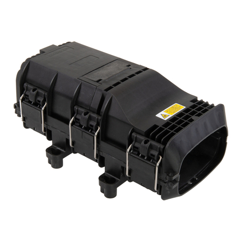
CommScope MDCC User manual

CommScope

CommScope MDCC User manual

CommScope CHD Series User manual

CommScope

CommScope CHD Series User manual

CommScope FOSC-500-AA User manual

CommScope

CommScope FOSC-500-AA User manual

CommScope NOVUX CC 100 User manual

CommScope

CommScope NOVUX CC 100 User manual

CommScope BUDI-M User manual

CommScope

CommScope BUDI-M User manual

CommScope BUDI-2S-SP User manual

CommScope

CommScope BUDI-2S-SP User manual

CommScope FOSC-450-BS User manual

CommScope

CommScope FOSC-450-BS User manual
CommScope FDH 3000 User manual

CommScope

CommScope FDH 3000 User manual
CommScope AEKT User manual

CommScope

CommScope AEKT User manual
CommScope Mini-OTE 300 Tap User manual

CommScope

CommScope Mini-OTE 300 Tap User manual

Popular Enclosure manuals by other brands

Antec Veris Fusion Remote Max Specification sheet

Antec

Antec Veris Fusion Remote Max Specification sheet

ENERMAX iVektor.Q ECA 3371 Series user manual

ENERMAX

ENERMAX iVektor.Q ECA 3371 Series user manual

Lindy 43095 user manual

Lindy

Lindy 43095 user manual

SICK C4000 Select operating instructions

SICK

SICK C4000 Select operating instructions

Geeek A60 PLUS installation guide

Geeek

Geeek A60 PLUS installation guide

OVE SYDNEY 48 installation manual

OVE

OVE SYDNEY 48 installation manual

SilentiumPC Armis AR5 Hardware installation

SilentiumPC

SilentiumPC Armis AR5 Hardware installation

Pulsar 17/TRP80/DSPR Assembly instructions

Pulsar

Pulsar 17/TRP80/DSPR Assembly instructions

MSI MPG SEKIRA 500X quick start guide

MSI

MSI MPG SEKIRA 500X quick start guide

Antec Dark fleet DF-10 user manual

Antec

Antec Dark fleet DF-10 user manual

Peavey DS 1502 Specifications

Peavey

Peavey DS 1502 Specifications

D-Link ShareCenter Pro DNS-1550-04 user manual

D-Link

D-Link ShareCenter Pro DNS-1550-04 user manual

Rosewill RX82-U(JBOD) user manual

Rosewill

Rosewill RX82-U(JBOD) user manual

QNAP SAS JBOD CLI 1.0 user guide

QNAP

QNAP SAS JBOD CLI 1.0 user guide

GAMDIAS Talos P1 Quick installation guide

GAMDIAS

GAMDIAS Talos P1 Quick installation guide

Auvs KR615 user manual

Auvs

Auvs KR615 user manual

Antec AR300 user manual

Antec

Antec AR300 user manual

FS FHD-FWME4 quick start guide

FS

FS FHD-FWME4 quick start guide

manuals.online logo
manuals.online logoBrands
  • About & Mission
  • Contact us
  • Privacy Policy
  • Terms and Conditions

Copyright 2025 Manuals.Online. All Rights Reserved.

1 Dimensions 2 Preparing RFP for installation onto the wall
•Within the appropriate location mount the wall mount bracket to the wall using two screws provided
3 Assemble Face Plate to support bracket
Align the face plate 90 degrees to the support bracket and push the assembly together .
Rapid Face Plate–RFP
Wall Mount Installation and Cable Routing Instructions
Infrared radiation is invisible and can seriously damage the retina of the eye. Do not look into the ends of any optical fibre. Do not
look directly into the optical adaptor. Exposure to invisible laser radiation may result. A protective cap or hood must be immediately
placed over any radiating adapter or optical fibre connector to avoid the potential of dangerous amounts of radiation exposure The
practice also prevents dirt particles from entering the connector and adapter
Issue 3 –16/08/13
Page 1of 2
PUSH THE FACE PLATE ONTO THE
SUPPORT BRACKET
4 UNSPOOL CABLE AND ROUTE TO EQUIPMENT
PULL FROM HAULING EYE
(MAXIMUM HAULING FORCE
SHOULD NOT EXCEED 7KG)
Using the hauling eye Gently pull the cable, make sure the RFP spins freely (DO NOT
EXCEED 7KG PULLING FORCE)
RFP WILL SPIN
DURING
INSTALLATION
WALL MOUNTING
BRACKET
POSITION THE FACE PLATE 90° TO
THE CAVITY SUPPORT BRACKET
115mm
52mm
75mm
ENSURE SURFACE MOUNT
BOX IS ORIENTATED
HORIZONTALLY
MARK AND SECURE TO
THE WALL USING THE
FIXINGS PROVIDED
NOTE RFP REMOVED FOR PICTURE CLARITY
SELECT APPROPRIATE PORT TO BE
UTILISED ON SUPPORT BRACKET
AND BREAKOUT PLASTIC COVER
7 Hauling eye removal
After the required cable is payed out, remove the
pulling eye as shown
6 Securing the face plate
Push the face plate into the support bracket
aligning the face plate with the support
bracket
8 Final Fixing and Closedown
Issue 3 –16/08/13
Page 2 of 2
RFP-1FII-WM
5 Managing the cable within the wall box
Secure the cable to the mounting bracket
CUT A SMALL PIECE
OF ADHESIVE FOAM
PROVIDED
Lift up the retention tab located
at the top of the connector
PULL THE BODY OF THE
CONNECTOR BACK TO RELEASE
THE DUST CAP
ATTACH FOAM TO CABLE
IN PREPARATION FOR
ANCHORING TO FACE
PLATE SECURE CABLE WITH
CABLE TIE PROVIDED VIEW FROM INSIDE WALL CAVITY
FEED CABLE INTO
FOAM SLOT AND
ANCHOR USING A
CABLE TIE
SECURE FACE PLATE TO
SUPPORT BRACKET USING 2
SCREWS PROVIDED
ASSEMBLE COVER TO
COMPLETE THE INSTALLATION
ENSURE CABLE IS LOCATED AT
THE TOP OF THE SPOOL