manuals.online logo
Brands
  1. Home
  2. •
  3. Brands
  4. •
  5. CommScope
  6. •
  7. Jack
  8. •
  9. CommScope AMP NETCONNECT User manual

CommScope AMP NETCONNECT User manual

1of 3
Instruction Sheet
408-10470
AMP NETCONNECT®Category 6A
Unshielded Twisted Pair (UTP)
AMP-Twist Modular Jacks
Figure 1
1. INTRODUCTION
This instruction sheet describesthe application of
Category 6A UTP AMP-Twist modular jacks.
NOTE
Dimensions in this instruction sheet are in metric units
[with U.S. customary units in brackets]. Figures are not
drawn to scale.
NOTE
i
Reasons for reissue of this instruction sheet are
provided in Section 5, REVISION SUMMARY.
2. DESCRIPTION (See Figure 1)
The modular jack consists of a front housing and back
housing. The back housing features a lacing cap and
identification label to aid in conductor arrangement.
The front housing features an interchangeable color
cap to color code the modular jack without having to
re-terminate the modular jack.
3. ASSEMBLY PROCEDURE
3.1.Cable Selection and Stripping
The jacksaccept four-pair twisted cable having solid
conductors sizes 24 through 22 and stranded
conductors size 24 AWG with a cable outer diameter
range of 5.0 through 9.0 mm [.197 through .354 in.].
Strip the cable to the dimension shown in Figure 2.
Figure 2
3.2. Terminating
1. Orient the cable conductors according to the wire
identification label on the lacing cap, then insert the
cable into the lacing capas shownin Figure 3.
2. Insert the cable until the jacket hits the stops as
shown in Figure 4.
3. Following the wire identification label, separate
the wire pairs by untwisting enough wire to lay
straight across the lacingcap and to the outside
edges.Refer to Figure 5.
Figure 3
Figure 4
Figure 5
4. Orient the lacing cap with the modular jack so
thatthe blue sideisaligned with the latch side as
indicated on the wire identification label. Refer to
Figure 6.
NOTE
Thelacingcap will notassembleto the modular jack if it
is oriented incorrectly.
Back
Housing
Front
Housing
Lacing
Cap
Color
Cap
Identification
Label
Note:Not to Scale
NOT
E
i
Dec. 2016 Rev C
©2016 CommScope, Inc.
All Rights Reserved
To obtain information on CommScope®products,
contact your local CommScope®account
representative, PartnerPRO™Network Partner
or visit our website at www.commscope.com
This product is covered by one or more U.S.
patents or their foreign equivalents. For patents, see
www.commscope.com/ProductPatent/ProductPatent.aspx
To obtain information on AMP NETCONNECT
®
products,
visit the CommScope®website at www.commscope.com
408-10470
2of 3
Rev C
Figure 6
5.
Pre-assemble the modular jack by snapping it onto
the lacingcap as shown in Figure 7. Thiswill secure
the lacing cap to the modular jack for termination.
Confirm that the arrows on either side of the
modular jack are aligned as shown in Figure 7.
Figure 7
6. Insert the pre-assembled modular jack into the
SL termination tool (refer to Instruction Sheet
408-8858). If the modular jack has a dust cover, the
dust cover must be opened before inserting the
modular jack into the tool. See Figure 8.
Figure 8
7. Squeeze the tool handle untilthe hookon the
bottom of the handle meets the top of the ram. The
wires will be cut automatically. See Figure 9.
8. Release the tool handle, and remove the modular
jack from the tool. The terminated modular jack
should appear as shown in Figure 10.
Figure 9
Figure 10
4. COLOR CAP CHANGE AND RE-TERMINATION
4.1. Changing Color Cap
The color cap of the modular jack can be changed as
follows:
1. Carefully insert a small flat screwdriver under the
color cap in the recessed area as shown in Figure 11.
Figure 11
Arrows Must Align
Modular Jack Without Dust Cover
Modular Jack With Dust Cover
Modular Jack Without Dust Cover
Modular Jack With Dust Cover
408-10470
3of 3
Rev C
2. Gently lift the color cap.
3. On the opposite side of the modular jack, lift the
color cap in the same manner to remove it.
4. Position the replacement color cap on the back
housing so that the top tab is oriented with the
corresponding cut-out in the color cap. See
Figure 12.
5. Rotate the color cap until the sides snap into
place.
Figure 12
4.2. Re-Terminating Modular Jack
1. Insert two small, flat head screwdrivers into the
channels in the back housing of the modular jack to
deflect the front housing side walls outward as
shown in Figure 13.
CAUTION
To avoid damage to the modular jack, do not pry the
housings apart when using the screwdrivers.
Figure 13
2. When the front housing side walls are fully
deflected, hold the front housing and the cable as
shown in Figure 14, and pull until the back housing
separates from the lacing cap and front housing.
See Figure 15.
3. Remove the cable, and terminate the modular
jack following the termination procedure.
Figure 14
Figure 15
5. REVISION SUMMARY
Revisions to this instruction sheet include:
•Rebranded to CommScope
!

Other CommScope Jack manuals

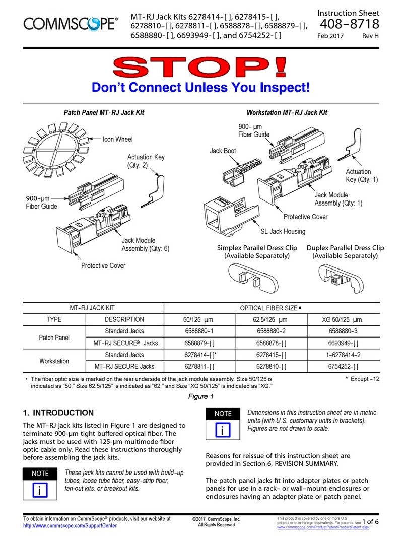
CommScope MT- RJ 6278414 Series User manual

CommScope

CommScope MT- RJ 6278414 Series User manual

Popular Jack manuals by other brands

Lippert Components JT's Strong Arm 191023 Installation and owner's manual

Lippert Components

Lippert Components JT's Strong Arm 191023 Installation and owner's manual

AirApp A Series Operating Instructions / Safety Instructions

AirApp

AirApp A Series Operating Instructions / Safety Instructions

Sealey AM20.V3 instructions

Sealey

Sealey AM20.V3 instructions

Sealey 1050CXLE.V3 quick start guide

Sealey

Sealey 1050CXLE.V3 quick start guide

Sealey RJA1550.V2 manual

Sealey

Sealey RJA1550.V2 manual

YATO YT-55600 manual

YATO

YATO YT-55600 manual

Cattini YAK 215/L Operating and maintenance manual

Cattini

Cattini YAK 215/L Operating and maintenance manual

Pro-Lift G2000 owner's manual

Pro-Lift

Pro-Lift G2000 owner's manual

Chicago Pneumatic CP9302 Instruction manual/safety instruction

Chicago Pneumatic

Chicago Pneumatic CP9302 Instruction manual/safety instruction

Clarke CTJ1250AC Operation & maintenance instructions

Clarke

Clarke CTJ1250AC Operation & maintenance instructions

K Tool International KTI63709 owner's manual

K Tool International

K Tool International KTI63709 owner's manual

Tronair 02-1032C0111 Operation & service manual

Tronair

Tronair 02-1032C0111 Operation & service manual

SGS TJH1.5 owner's manual

SGS

SGS TJH1.5 owner's manual

SATA 97816 user manual

SATA

SATA 97816 user manual

Sunex Tools 6622A owner's manual

Sunex Tools

Sunex Tools 6622A owner's manual

NEO TOOLS 11-712 instruction manual

NEO TOOLS

NEO TOOLS 11-712 instruction manual

Sealey 2500LE.V3 manual

Sealey

Sealey 2500LE.V3 manual

Tronair 02-1036C0111 Operation & service manual

Tronair

Tronair 02-1036C0111 Operation & service manual

manuals.online logo
manuals.online logoBrands
  • About & Mission
  • Contact us
  • Privacy Policy
  • Terms and Conditions

Copyright 2025 Manuals.Online. All Rights Reserved.