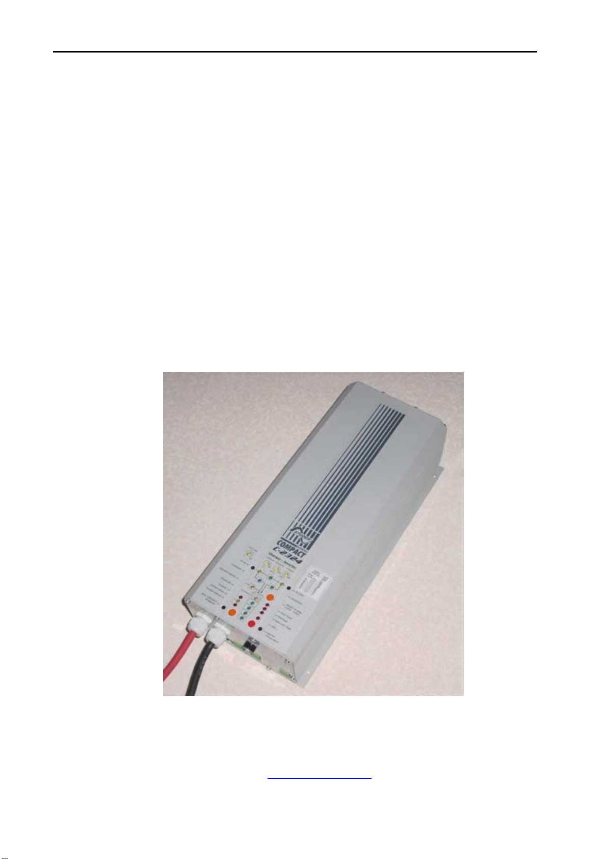
Studer Solartechnik Sinewave Inverter, Battery Charger
- 7 -
OPERATION of the COMPACT
The Inverter
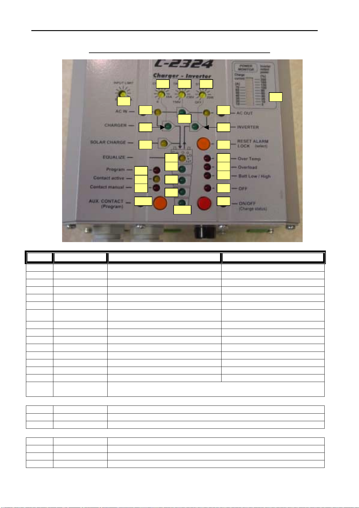
When operating in Inverter Mode LED 9* (Inverter) will illuminate. This indicates that 230Vac is being
delivered to the AC OUTPUT with the power being derived from the batteries. The inverter automatically
switches on if the AC INPUT is out of the preset limits. The power being taken from the inverter by the
AC load (consumer appliance) is displayed as a percentage of the maximum power of the unit on the
Power Monitor (25)*. The inverter has a 3-times full power surge capability for starting large motors
etc.
Standby Mode
When in Inverter Mode the COMPACT continually monitors the load on the AC OUT. If this load falls
below a presettable level, set by the ‘Standby’* knob, the Inverter will switch OFF to avoid taking
power unnecessarily from the batteries. This load can be adjusted between 1 to 20 Watts using the
‘Standby’* knob. The Inverter will then briefly switch on every second to check if the load has
changed. When in ‘Standby’ Mode LED 8* (AC OUT) will flash. Once the load is above the preset level
the inverter will automatically switch to normal operating mode.
To set the Standby mode to the correct level firstly switch off all AC appliances connected to the AC
OUTPUT. Turn the ‘Standby’* knob anti-clockwise until LED 8* is flashing. Connect the smallest load
that will be used, e.g. mobile phone charger, to the AC OUTPUT. Turn the ‘Standby’* knob clockwise
until LED 8* illuminates continuously. If Standby Mode is not required and the inverter is to operate
regardless of the load then turn the ‘Standby’* knob fully anti-clockwise to the OFF position.
Overload
The inverter is designed to operate continuously at its full rated power or for short periods above this
rated power. If the unit is operated for long periods above its maximum rating it will shut down
automatically. At this point the ‘Overload’ LED 11* will illuminate and the ‘OFF’ LED 13* will flash.
After 10 seconds the inverter will switch ON again automatically. If the inverter is overloaded 4 times
within a short period of time then it will no longer switch ON automatically and the ‘ON/OFF’ button
19* will need to be pushed to restart the unit.
Over Temperature
The COMPACT has an internal cooling fan that switches ON when the ambient inside the unit reaches a
certain level. If there is insufficient ventilation around the unit, or if the external ambient temperature
exceeds the maximum level, the COMPACT will shutdown due to over-temperature within the unit when
operated at high power. At this point the ‘Over Temp’ LED 10* will illuminate and the ‘OFF’ LED 13*
will flash. One minute before the unit switches OFF an audible alarm will sound. The unit will restart
automatically after cooling down.
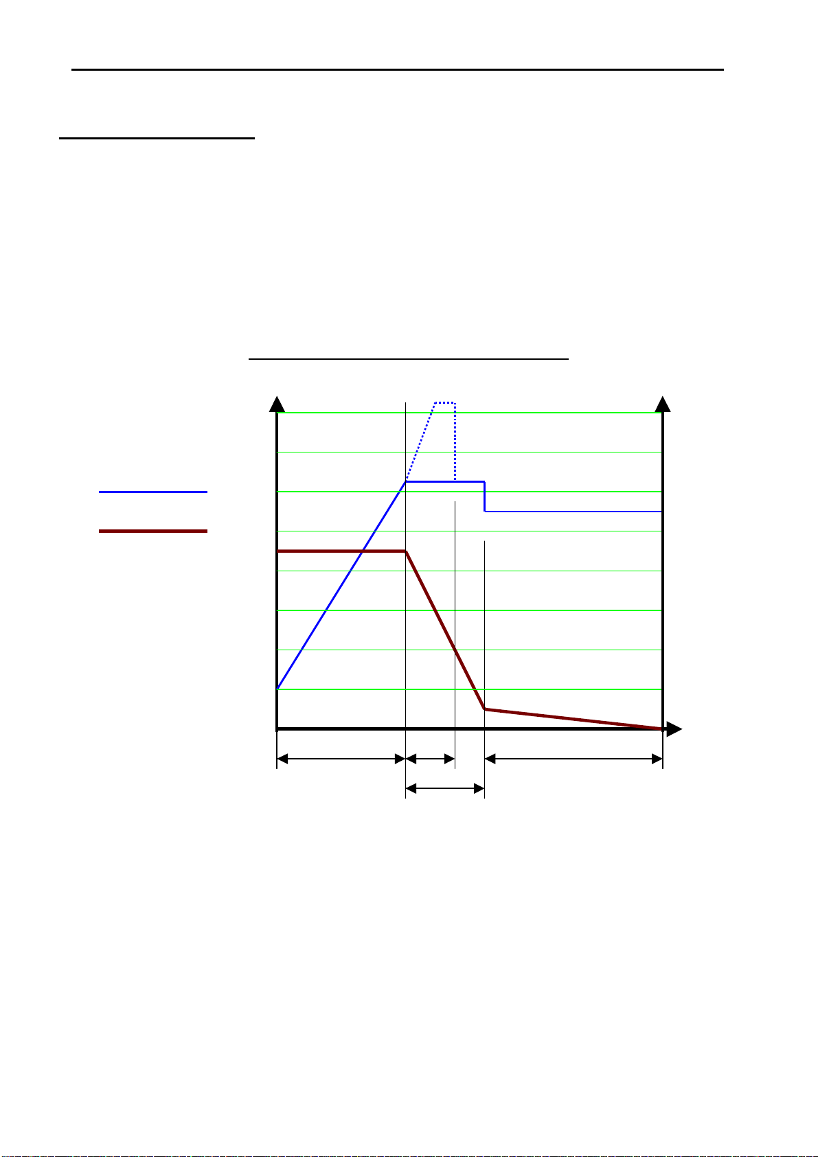
Battery Condition
Deep discharge leads to high reduction of capacity and early ageing of the batteries. When the battery
voltage drops too low (see below) the inverter will switch OFF automatically. At this point the ‘Batt
Low/High’ LED 12 will illuminate and the ‘OFF’ LED 13 will flash. One minute before the inverter
switches OFF an audible alarm will sound. The unit will automatically restart after the battery volts
increase above the minimum switch ON level (see below).
**Switch OFF level 12V unit 11.8V 24V unit 23.6V 48V unit 47.2V
**Switch ON level 12V unit 12.1V 24V unit 24.2V 48V unit 48.4V
*
Please refer to the ‘Display and Operating Panel’ photograph on page 6
**
These are the levels pre-programmed into the COMPACT and recommended by most battery
manufacturers. If required these values can be altered. See Programming.