COMPARATO NELLO SRL
2
Notices ___________________________________________________________________________
Technical features ________________________________________________________________________
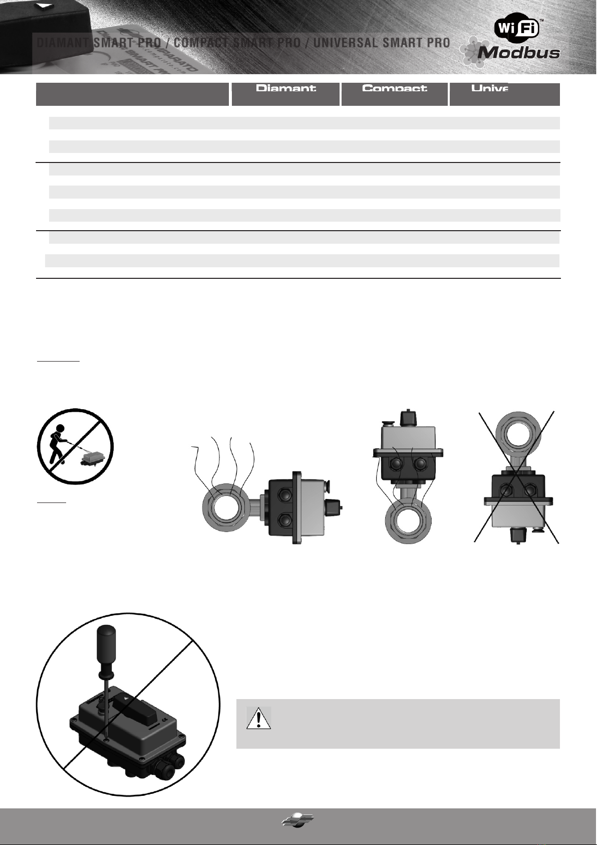
Installation ______________________________________________________________________________________________
Connection to the ball valve _______________________________________________________________________________________________
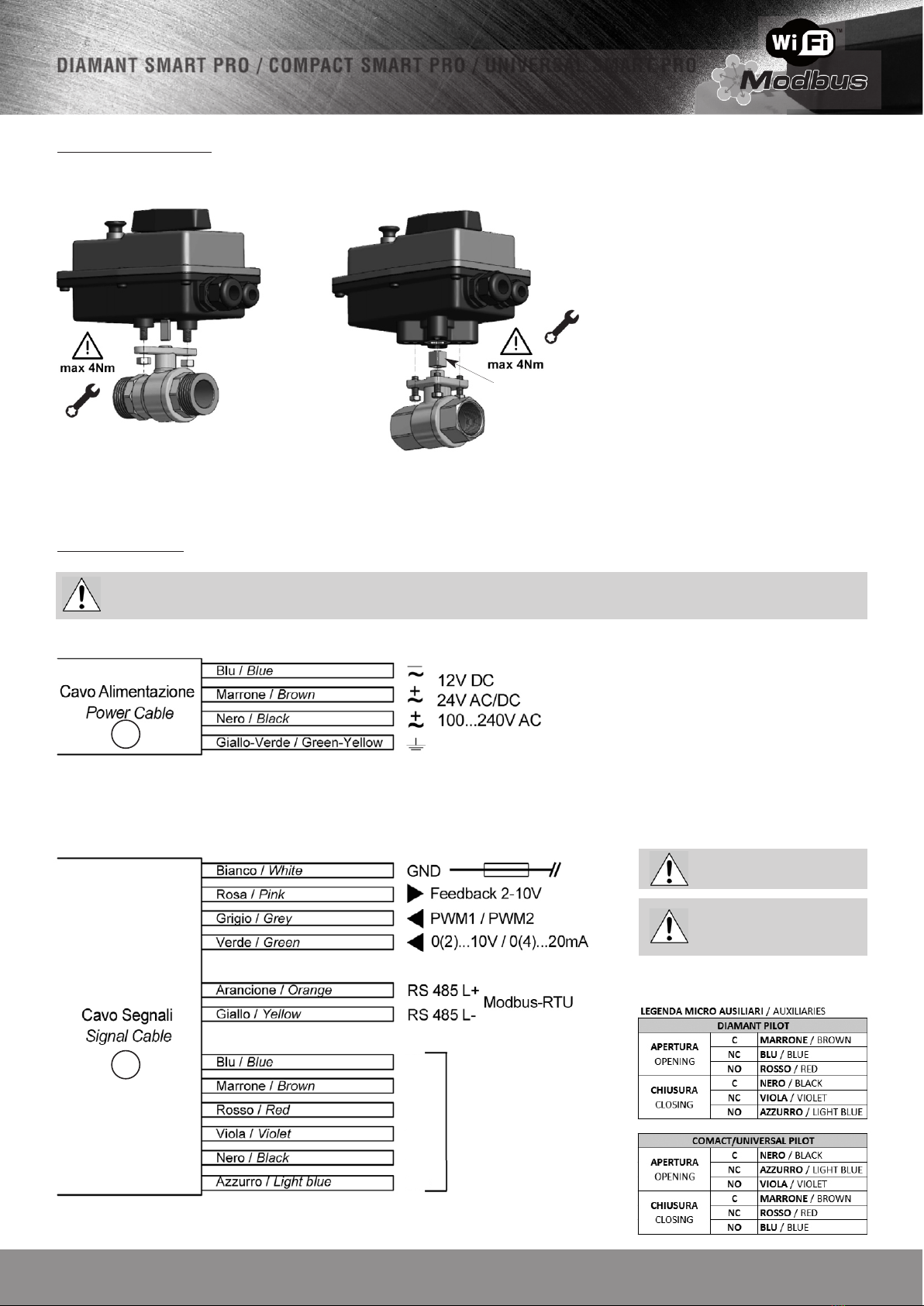
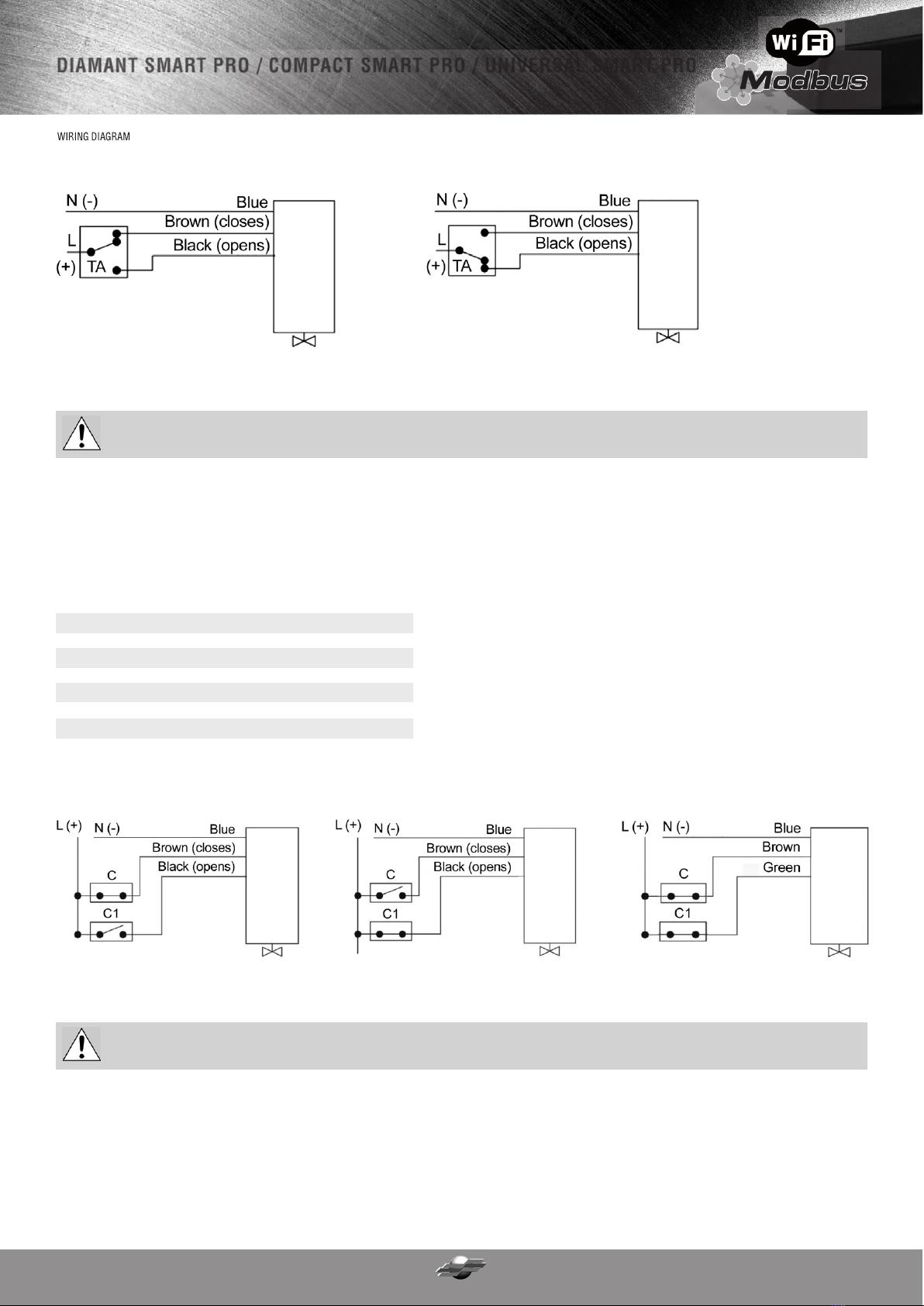
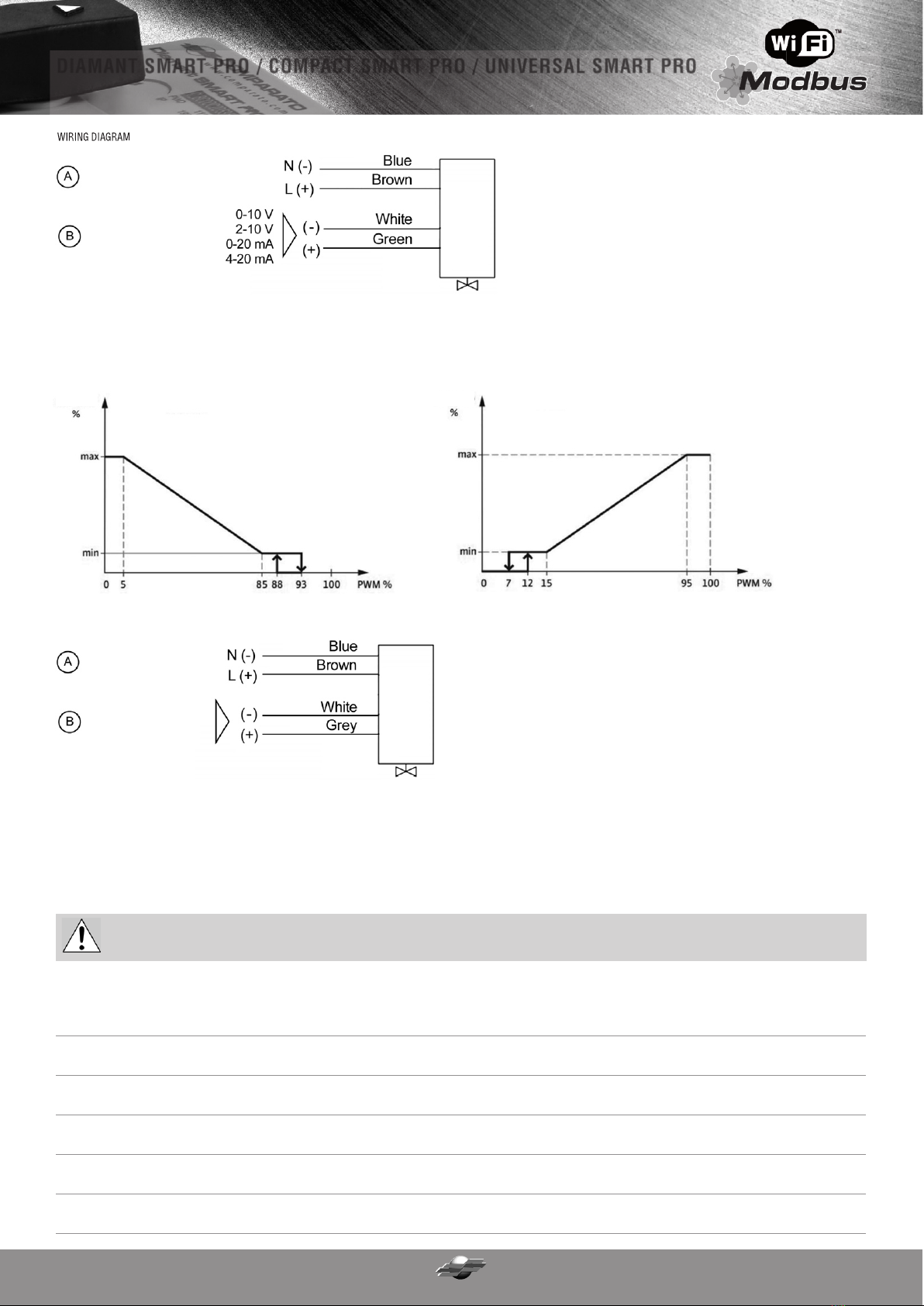
Electrical connections __________________________________________________________________________
Reference positions __________________________________________________________________________
Emergency manual opening __________________________________________________________________________
Auxiliary microswitch signals __________________________________________________________________________
Position feedback __________________________________________________________________________
Operation __________________________________________________________________________
Fail Safe (optional) __________________________________________________________________________
Motor anti-overheating (optional upon request) __________________________________________________________________________
Monitoring __________________________________________________________________________
Wi-Fi communication (optional) __________________________________________________________________________
Serial RS458 communication - Modbus (optional) __________________________________________________________________________
Operating anomalies __________________________________________________________________________
General warranty conditions __________________________________________________________________________
NOTICES
Read the warnings contained in the manual carefully, since they provide important information about safe installation, use and maintenance. Installation and maintenance shall be performed in accordance with the
relevant regulations and the manufacturer's instructions. In case of failure and/or malfunctioning of the appliance, do not attempt any repair or direct servicing. Always contact qualified personnel, as provided by
law. Only qualified technicians are allowed to carry out any repair operation. Failure to comply with the provisions listed above may compromise the safety of the appliance.
TECHNICAL FEATURES
TABLE OF CONTENTS
2
2
3
4
4
6
6
7
7
7
12
13
13
14
16
18
18
DANGER:
DANGER:
12Vdc • 24Vdc • 24V 50/60 Hz • 100...240V 50/60 Hz
10W 25W 25W
2W 3W 3W
3W 5W 5W
11Nm 22Nm 40Nm
Diamant
SMART PRO Compact
SMART PRO Universal
SMART PRO
Power supply
Maximum power consumption during operation
Power consumption during standby
Heating resistance power
Supply cable
Signal cable
Auxiliary micro output
Rated torque
Control type ON/FF
Proportional positioning signal
Position signal dead band
Position signal impedance
Positioning feedback
Maximum position feedback current
Positioning accuracy
Motor rotation direction
Manual override
Rotation angle
Angular positioning correction
Operating time ( 90°)
Maximum noise
Protection degree
Connection to the valve
Accumulator
Emergency position
Fail safe operating time ( 90°)
Minimum charging time
Maximum power consumption
4 x 0,5 mm^2 (AWG 20) - Length 1m
12 x 0,2 mm^2 (AWG 24) - Length 1m
max 30Vdc - 0,1 A
2-point • 3-point • 0°- 45° - 90° • 0°- 90° - 180°
0-10V • 2-10V • 0-20 mA • 4-20 mA • PWM1 • PWM2
Adjustable: 1% • 3% • 5%
100kΩ(0-10V / 2-10V) • 500kΩ(0-20 mA / 4-20 mA) • 133kΩ(PWM)
2-10Vdc
40 mA
+/- 5%
Reversible
Release lever and button
90° • 180°
With Modbus or Wi-Fi interface
DIAMANT SMART PRO / COMPACT SMART PRO / UNIVERSAL SMART PRO
ELECTRICAL DATA
ELECTRICAL DATA
FAIL SAFE
15s* • 30s • 60s • 120s 15s* • 30s • 60s • 120s 30s • 60s • 120s
45 dB (A) 60 dB (A)
Supercapacitors
Programmable opening / closing / intermediate
IP67
65 dB (A)
0,6 W 3 W 3 W
20s 26s 30s **
15 min (90°) • 60 min (180°) 9 min (90°) • 18 min (180°) 50 min (90°)
Comparato • ISO 5211 F03/F05 ISO 5211 F03/F05 ISO 5211 F05/F07
* time not available with 12Vdc power supply.
** for the 180° rotation angle fail safe operation, please contact our technical office.
Electrical hazard! The unit contains high-voltage equipment.
Scalding hazard! Even in normal operation conditions, the unit can reach very high temperatures which may cause scalds.