Comparato NELLO DIAMANT 2000 User manual


USE
Diamant 2000 / Diamant
PRO
motorised valve are specifically used for the inter-
ception and regulation of fluids in:
• zone heating systems
• systems using alternative energy
• industrial systems in general using hot and cold fluids
• automation systems in general
• glycol cooling systems
• chemical industry and pharmaceutical industry systems
The
Diamant 2000 / Diamant
PRO
series are the leading models of Comparato’s
range of products, for both industrial and residential purposes.
COMPARATO NELLO SRL
1
Diamant 2000
Diamant
PRO
NAME:
The following data are indicated on the housing of the actuator:
• Trademark and name of the manufacturing company: Hydrothermal systems
COMPARATO NELLO
s.r.l.
Viale della Libertà, 53 • Località Ferrania
17014 Cairo Montenotte (SV) • ITALY
• Models: DIAMANT 2000 / DIAMANT PR
• Production date: Year
• EC regulations compliance
• Supply voltage
• Type of connection
• Auxiliary micro switch, if any
• Wiring diagram (inside the cover)

P SITI N
T1 - T4
P SITI N
T4 - T3
P SITI N
T3 - T2
P SITI N
T2 - T1
T1
T2
T3
T4
P SITI N
L1 - L2
OP CL
OP CL
HORIZONTAL 3-WAY BALL VALVE:
Available version with “T BALL (3 holes) and “L BALL (2 holes).
HORIZONTAL 3-WAY versions are available with 2 different balls
and a total of 5hole positions.
BIDIRECTI NAL engine, 90° operation.
2
COMPARATO NELLO SRL
Diamant 2000
Diamant
PRO
INSTALLATION
CAUTION! FOR ALL DIAMANT 2000 / DIAMANT PRO ACTUATORS
nce installed, the actuator connection should not be at the bottom of the valve. When the valve
works with low-temperature fluids (potential frost formation on the valve stem) or with high-tempe-
rature fluids (danger of actuator overheating), it is advisable to install it in the correct position, as
shown in the picture.
2-WAY BALL VALVE:
The 2-WAY
Diamant 2000 / Diamant
PRO
have no constrained flow direction,
therefore their installation is not particularly difficult: in fact, the cut-off is made up of a ball with a
through hole. The actuator is supplied in the open position. The installation should be carried out as
shown in the picture.
POSITIONS LAYOUT AND BALL HOLES MOVEMENT
RECOMMENDED POSITION ALLOWED POSITION FORBIDDEN POSITION

Diamant 2000
Diamant
PRO
180° PERATI N
Hole reference A
3-WAY VERTICAL BALL VALVE WITH 2-HOLE BALL (DIVERTER)
The 2-HOLE ball version should be used when fluids must not come into contact
during the operation phase (deviation).
ne of the ball holes (B) is constantly pointed towards the common way of the
ball valve, while the other one (A) can be aligned to one of the opposed ways or
to the other, with a 180° rotation.
During the movement, there is no fluid mixing.
COMPARATO NELLO SRL
3
Hole reference B Hole reference B Hole reference B
Hole reference A Hole reference A
0°
0°
90° 180°
180°
CONTROL ROD, PLAN DETAIL
The ball valve is supplied in POSITION 1. Referring to the ball valve as shown in the picture, the com-
municating ways are the LEFT and the BOTTOM ones.
During the operation, the fluid flow is progressively cut off on the LEFT side; the flow remains inter-
rupted for a few seconds and then is progressively opened again, on the RIGHT side. The actuator
rotates 180° and the ball rotates counter clockwise.
Now the communicating ways are the RIGHT and the BOTTOM ones.
POSITION 1
Hole reference A Hole reference A
POSITION 2

Diamant 2000
Diamant
PRO
4
COMPARATO NELLO SRL
90° PERATI N
Hole reference A Hole reference A
Hole
reference C
Hole
reference C
Hole reference B
Hole reference A Hole reference C
Hole reference C Hole reference A
Hole reference B Hole reference B
Hole
reference C
Hole reference A
0°
0°
0°÷90° 90°
90°
3-WAY VERTICAL BALL VALVE WITH 3-HOLE BALL (MI ING)
The 3-HOLE ball version should be used when fluids must come into contact
during the operation phase (mixing).
ne of the ball holes (B) is constantly pointed towards the common way of the
ball valve, while the other two holes (A & C), placed at 90° to each other, allow
the full flow between one of the two opposed ways and the common (central)
one, or any intermediate mixing position.
The complete operating angle is 90°.
CONTROL ROD, PLAN DETAIL
The ball valve is supplied in POSITION 1. Referring to the ball valve as shown in the picture, the com-
municating ways are the LEFT and the BOTTOM ones. During the operation, the fluid flow is progres-
sively deviated from the LEFT way to the RIGHT way, without ever interrupting the flow. The actuator
rotates 90° and the ball rotates counter clockwise.
Now the communicating ways are the RIGHT and the BOTTOM ones.
POSITION 1 (opening) POSITION 2 (closing)

Diamant 2000
Diamant
PRO
COMPARATO NELLO SRL
5
TECHNICAL DATAS OF BALL VALVES
Nominal Differential Minimum Maximum Minimum Maximum
Type
2/3-WAY / By-pass 16 bar 16 bar -10°C +110°C
2-WAY IS 5211 40 bar 16 bar -10°C +110°C
3-WAY IS 5211 H RIZ.
Ø 1/4" - 3/4" 30 bar 16 bar -10°C +110°C
Ø 1" 16 bar 16 bar -10°C +110°C
3-WAY IS 5211 VERT.
Ø 1/2" 25 bar 16 bar -10°C +110°C
Ø 3/4" - 1" 16 bar 16 bar -10°C +110°C
2-WAY AISI 316 64 bar 16 bar -10°C +110°C
2-WAY PVC 16 bar 16 bar 0°C + 25°C
3-WAY PVC 10 bar 16 bar 0°C + 40°C
Pressures Temperatures Temperatures
Valve with spacer
-20°C +110°C
-20°C +160°C
-20°C +160°C
-20°C +160°C
-20°C +120°C
-20°C +120°C
-20°C +160°C
BY-PASS BALL VALVE
The BY-PASS type ball valve should be used in heating systems when the fluid has to be intercepted,
allowing a limited flow between outlet and return.
The ball has a through hole and it is faced; therefore, in the open position, the operation is similar
to that of a two-way ball valve. In the closing position, the faceting generates the BY-PASS, allowing
the communication between the intercepted way to the central one.
By-pass
faceting
CL SED VALVE
PEN VALVE
CONTROL ROD, PLAN DETAIL
By-pass
faceting reference By-pass
faceting reference
0° 90°
Opening Closing
ACTUATOR’S OPTIONALS
Diamant 2000 and Diamant PR actuators can be provided with emergency manual override on the
top (see picture 1) or lever on the spacer for insulation (the spacer is also available without lever for
manual override, see picture 2).

HOW TO INSTALL THE SPACER FOR INSULATION WITH LEVER FOR MANUAL OVERRIDE (2)
MANUAL OVERRIDE DIRECTION (1)
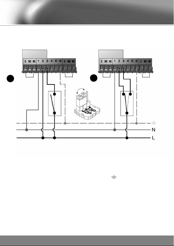
Push the button and rotate
the lever ANTI-CL CKWISE
Actuator with
90° rotation
Actuator with
180° rotation
ATTENTION
The valve can be manually operated only when
electrically disconnected or if the actuator is bro-
ken. If the valve is blocked, please follow below
instructions:
• disconnect the actuator
• remove the actuator
• try to move the ball using a screwdriver or a
wrench suitable for the valve rod.
We would recommend not to overstress the valve
to avoid damages to the body or to the actuator’s
connection. If the ball remains blocked, remove
and replace the valve.
CABLE GLANDS SIDE
Please proceed as per following instructions and be careful
to respect positioning of all components:
1.Place the actuator with cable glands oriented towards you
and put the spacer with the vertical connection piece on the
right side.
2. With the actuator in open position, fix the central rod
paying attention that the lever for the manual opening is
opposite to the cable glands.
3. Tighten the screws to fix the spacer between valve and
actuator.
4. Electrically connect the actuator and make it open and
close to test it works properly. Looking the actuator from
above, you will see the lever moving anticlockwise from
open to close position.
ATTENTION:
Not compliance with the provisions above may cause dange-
rous situations for operators and/or the system integrity..
Diamant 2000
Diamant
PRO
6
COMPARATO NELLO SRL

Diamant 2000
Diamant
PRO
COMPARATO NELLO SRL
7
ELECTRICAL CONNECTIONS
TECHNICAL FEATURES OF THE ACTUATOR
Before making the electrical connections the supply power must be properly disconnected by quali-
fied personnel, according to the diagram shown under the cover.
To make the connections, unscrew the screws and remove the housing cover in order to access the
terminal strip and the printed circuit board. Remove the side plug which closes the cable gland hou-
sing, screw the cable gland and proceed to the electrical connection. During the electrical connection,
tighten the cable in the cable gland and make sure it is properly placed (fig. 2-3), close the cover
tightening the screws; the seal must fit perfectly in its housing (fig. 1).
Tighten the screws with a manual screwdriver.
Note: any electrical connection which does not comply with the attached diagrams can seriously dama-
ge the equipment.
• Electric motor: bidirectional
• Power supply: 230V o 110V o 24V 50Hz (60Hz on demand)
• perating time ( 90°) : 35 sec. Torque 11 Nm • ( 180°) : 70 sec. Torque 11 Nm
( 90°): 12 sec. Torque 11 Nm • ( 180°) : 24 sec. Torque 11 Nm
( 90°): 4sec. Torque 5Nm • ( 180°) : 8sec. Torque 5Nm
• Maximum power consumption: from 4,8 VA (230V 50 Hz version)
from 5,1 VA (110V 50 Hz version)
from 5,2 VA (24V 50 Hz version)
• Class protection: IP 65 (DIAMANT 2000) / IP 67 (DIAMANT PR )
• Power output of the auxiliary micro: 1A, resistive
• perational room temperature: minimum -10°C maximum 50°C
FIG.3
FIG.2
FIG.1
SUITABLE
NOT SUITABLE

Diamant 2000
Diamant
PRO
8
COMPARATO NELLO SRL
The electrical systems must be planned taking into account the environment they will be installed
into. The IP class protection of electrical components indicates its level of protection against the
penetration of solids and liquids.
The actuators were designed to have an IP65 (Diamant 2000) and IP67 (Diamant PR )electrical pro-
tection (it is recommended to keep away from direct sunlight and to stick to the allowed temperature
range).
All the other equipments must be earthed.
Moreover, thermo-magnetic switches, fuses and circuit breakers must be installed upstream the actua-
tor, in order to ensure the compliance with the safety condition required by the existing laws.
ALL DIAMANT 2000 / DIAMANT PR M T RIZED VALVES ARE EQUIPPED WITH AN “ALL IN ONE”
SYSTEM, which allows to set the 2-POINT or 3-POINT electrical control with a jumper-type selector,
according to the user’s needs (as shown in the pictures below).
ELECTRICAL FEATURES:
CAUTION
In case of replacement, if the 3-POINT actuator version is earlier than the ALL-IN-ONE one, reverse
the connection on the terminal strip 2& 3.

Diamant 2000
Diamant
PRO
COMPARATO NELLO SRL
9
DIAMANT ELECTRICAL CONNECTIONS
The “a” figure shows the connections of the 2-POINT actuator. The fixed phase must be connected
to terminal 2; at the same time, the phase on terminal 3causes the valve to open, whereas cutting
the phase on the same terminal, it closes (automatic electrical closing).
The “b” figure shows the connections of the 3-POINT actuator. If the phase is present on terminal 2,
the valve connected to the actuator closes; instead, if the phase is on terminal 3, the valve opens
(no contemporaneous phase on terminal 2and 3is allowed).
Connect the neutral on terminal 1 both for 2-POINT and 3-POINT versions.
With the 2-POINT connection, it is possible to activate multiple actuators with the same control devi-
ce (thermostat, relay, etc.) With the 3-POINT connection, it is possible to activate only one actuator
with a control device and to make in-between settings in order to make a modulation, provided it is
used with a suitable control device.
2-POINT CONNECTION
usually electrically CL SED
3-POINT CONNECTION
M1 A X. MICRO SWITCH FREE IN OPEN POSITION
M2 A X. MICRO SWITCH FREE IN CLOSING POSITION
M1 M2
AB
D
E
E
CAPTION:
1- Neutral
2- Closing phase
3- pening phase
4- utlet opening phase
5- utlet closing phase
C- Common
NO - Normally open
NC - Normally closed
M1 - pening auxiliary micro
M2 - Closing auxiliary micro
A- Cutout-type control
B- Switch-type control
D- Closing
E- pening
F- Jumper
- Earth
F
M1 M2
b
a

Diamant 2000
Diamant
PRO
10
COMPARATO NELLO SRL
E AMPLES OF ELECTRICAL CONNECTIONS
CONNECTION OF AU ILIARY MICROS
M1(opening auxiliary micro) M2(closing auxiliary micro)
Control
contact
Control
contact Pump
M1 A X. MICRO SWITCH FREE IN OPEN POSITION
M2 A X. MICRO SWITCH FREE IN CLOSING POSITION
CONNECTION OF THE PUMP STOP WITH TWO OR MORE 2-POINT ACTUATORS
M1 A X. MICRO SWITCH FREE IN OPEN POSITION
M2 A X. MICRO SWITCH FREE IN CLOSING POSITION
CONNECTION OF THE PUMP STOP WITH TWO OR MORE 3-POINT ACTUATORS
Control
contact
Control
contact Pump
N N- PEN VALVE
PEN VALVE
N N-CL SED VALVE
CL SED VALVE

Diamant
PRO
COMPARATO NELLO SRL
11
ANTI-CONDENSING HEATER
The anti-condensing heater prevents the risk of condensation inside the actuator.
To activate the heating effect of the resistance, connect the two resistance wires using suitable
faston connectors.
The supply voltage must be equal to the one indicated on the tag.
The technical features are indicated on the adhesive tag.
Anti-condensing
Heater

Diamant 2000
Diamant
PRO
12
GENERAL WARRANTY CONDITIONSA
WARRANTY
The
Diamant 2000 / Diamant
PRO
motorised valves are covered by a 5-year war-
ranty (except
Diamant
PRO
with ISO 5211 connection, which is covered by a 3-year warranty),
from the date marked on the base of the actuator (year of production). For any returned good, users
should contact the Reseller they bought the items from.
The goods should be returned postage-free.
DURING THE WARRANTY PERIOD
During the warranty period,
COMPARATO NELLO
S.r.l. will repair or replace, free of char-
ge, any product or component, provided it turns out to have a manufacturing defect. Any repair or
replacement of the component or of the product itself does not extend the warranty period.
COMPARATO NELLO
S.r.l., reserves the right to replace the Product with an identical
one; if the product is out of production, it will be replaced with one with identical specifications,
provided that, according to the unquestionable opinion of
COMPARATO NELLO
S.r.l., the repair is not economically excusable.
WARRANTY E CLUSION PROVISION
Interventions and/or repairs and/or spare parts will not be covered by this Warranty if it turns out
that they are defective because of:
• tampering
• failure due to carelessness and/or unskilfulness during the installation (wrong, incomplete or
missing assembling/wiring/setting)
• electrostatic discharge, electric discharge conducted/induced because of lightning or other
phenomena not ascribable to the product, irradiated electromagnetic disturbances, intermittent
or discontinuous power supply.
• defects or damages caused by fall, breakage, liquid seepage
• repairs made by unauthorized people
• products with expired warranty
• systems made in a non-workmanlike manner
• any other damage not directly ascribable to
COMPARATO NELLO
S.r.l.
In order to provide an up-to-date service, Comparato Nello S.r.l. reserves the right to modify
technical data, drawings, graphs and photos of this instruction manual at any time, without prior notice.
COMPARATO NELLO SRL

Diamant 2000
Diamant
PRO
COMPARATO NELLO SRL
13

Diamant 2000
Diamant
PRO
14
COMPARATO NELLO SRL

HYDROTHERMAL SYSTEMS
COMPARATO NELLO SRL
OFFICE: IALE DELLA LIBERTÀ, 53 • LOCALITÀ FERRANIA
17014 CAIRO MONTENOTTE (S ) • ITALY
TEL. +39 019 510.371 • FAX +39 019 517.102
www.comparato.com [email protected]
1ISTRDIAMANT • SEVENTH EDITION, DECEMBER 2014
This manual suits for next models
10
Table of contents
Other Comparato Control Unit manuals
Popular Control Unit manuals by other brands

Taco
Taco ZVC404-EXP-4 instruction sheet

Dover
Dover Midland A-720 Series Installation, operation & maintenance manual

Phytec
Phytec phyCORE-MPC5200B tiny Hardware manual

Frequency Central
Frequency Central System X CV Mixer Build documentation

Bryant
Bryant Evolution SYSTXBB4ZC01 Installation and start-up instructions

ASCO Valves
ASCO Valves 8210 Series Installation & maintenance instructions