Compex SGX3224 User manual

“Quick Install Guide”
Compex
24 - Port All 10/100
Management Switch
SGX3224
SGX3224 PLUS
Version 1.1C
ReadyLINK

†
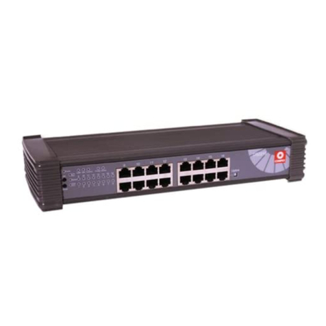
Figure 1: Front Panel View of SGX3224
‡
Figure 2: Front Panel View of SGX3224(Section #1)
ƒ
Figure 3: Front Panel View of SGX3224(Section #2)
Figure 4: Back Panel View of SGX3224
Console
100-250VAC
3.0A 47-63Hz
•
ˆ

ƒ
„‰
Figure 5: Front Panel View of SGX3224 PLUS
Figure 6: Front Panel View of SGX3224 PLUS(Section #1)
…
Figure 7: Front Panel View of SGX3224 PLUS (Section #2)
Figure 8: Back Panel View of SGX3224 PLUS
Š
Console
100-250VAC
3.0A 47-63Hz

Contents
≥≥ English Text
Diagrams Front Flap
Introduction Page 1
Key Features Page 1
Hub Features Page 2
SGX3224 Specification Page 5
1000Base-SX Gigabit Uplink
Specification (Factory Installed
Option)
Page 6
100Base-FX Fiber optic Uplink
module Specification Page 7
Installation of SGX3224 Page 7
Installation of 100Base-TX
Optional Module Page 8
Troubleshooting Page 8
Advance Management Functions
Setup Procedures Page 9
Login to Web Browser Interface Page 10
Setting up of Port Transmission
Mode Page 12
Viewing Basic Statistic Page 13
Port VLAN Setup Page 14
Save Configuration and Restore
Factory Default setting Page 15
≥≥ German Text Page 17
≥≥ Russian Text Page 33
≥≥ French Text Page 55
≥≥ Technical Support Last Page

English Compex 24 - Port All 10/100 Management Switch
(SGX3224, SGX3224 PLUS) 1
“Quick Install Guide”
Compex 24 - Port All 10/100 Management Switch
(SGX3224, SGX3224 PLUS)
Introduction
Compex SGX3224 is an all 10/100 24-port Management Ethernet Switch.
Compex SGX3224 PLUS has all the functions of SGX3224 plus one additional
1000Base-SX Gigabit Ethernet port for Uplink connection. All the 24 10/100
ports are on independent switching segment with full duplex capability, and this
provides up to 4.8 Gbps bandwidth for the 10/100 connections. Uplink switch is
provided on one of the ports so that you can use a normal straight through cable
for connecting two switches. SGX3224 PLUS with the gigabit connection
supports the Multi-mode fiber for 200m. All ports, including Gigabit port
(SGX3224 PLUS), support full duplex operation, which allows bandwidth to be
doubled for every port. Furthermore, port 1 is a shared port on which user can
insert a fiber optic module for 100Base-FX connection; after this 100Base-FX
fiber module is inserted, RJ-45 UTP port 1 will be disabled.
Key Features
The key features of the Compex 24-Port All 10/100 Management
Switch (SGX3224, SGX3224 PLUS) are as follows:
§Each port supports 10Base-T and 100Base-TX connection through
auto-negotiation.
§24 high-speed ports provide switching between 10Base-T Ethernet
segments and 100Base-TX Fast Ethernet segments in a single
integrated network.
§Store-and-forward switching scheme.
§Supports 10Base-T to 100Base-TX connectivity, allowing for
progressive migration.
§Support Full Duplex and Half Duplex for both 10Base-T and
100Base-TX connection at each port.
§Optional factory installed Gigabit Uplink connection supporting
200m 62.5/125um and 550m 50/125um multi-mode fiber optic
cable for 1000Base-SX(SGX3224 PLUS only).
§100Base-FX fiber optic uplink module supports 2000m
62.5/125um and 50/125um multi-mode fiber optic cable.
§N-way auto-negotiation.

2Compex 24 - Port All 10/100 Management Switch
(SGX3224, SGX3224 PLUS) English
§Buffer RAM size of 12Mbytes for SGX3224 PLUS only.
§4Mbytes buffer RAM for Gigabit Uplink factory installed option
(SGX3224 PLUS only).
§Support up to 12KMAC addresses.
§IEEE802.3x flow control for full duplex operation.
§Back pressure flow control for half duplex operation.
§SNMP manageable.
§MIB supported: MIB II, Bridge MIB, Proprietary MIB, RMON
MIBS.
§RMON capability: four RMON groups supported – Ethernet
Statistics, Alarm, History and Event group.
§Port VLAN function supported.
§Change of transmission mode supported (10Base-T half duplex,
10Base-T full duplex, 100Base-TX half duplex, 100Base-TX full
duplex or N-way Auto-negotiation) through any management
interface.
Hub Features (see diagrams on inner cover)
1POWER LED: ♦LED ON indicates hub is receiving power.
2100 LEDs ♦Link Status for 100Mbps connection for
Ports ‘P1’ to ‘P24’. LIGHTS UP when
connected to100Mbps segment.
3FD LED ♦Full Duplex LED: LIGHTS UP when
particular port is running at Full Duplex
mode.
4ACT/LINK
LEDs ♦Activity LED and Link Status for Ports ‘P1’
to ‘P24’. BLINKS indicate network activity
is present.
♦STEADY LIGHT indicates a good cable
connection to the SGX3224’s port.
5COL ♦
Indicate collision at the network segment of
the respective port.
624 RJ-45 Ports ♦RJ-45, 100Base-TX/10Base-T ports; Auto-
negotiation.
Configured as 24 UTP Ports or 23 UTP
ports plus 1 Uplink Port.
7Uplink Button
('P1') ♦Normal mode when button is pushed IN.
♦Uplink mode when button is released OUT.

English Compex 24 - Port All 10/100 Management Switch
(SGX3224, SGX3224 PLUS) 3
8Power Socket ♦Flexible power input (range 90VAC to
265VAC) meets every country requirement.
91000Base-SX
Port ♦Gigabit Uplink connection.
10 Link ♦Link Status for Ports ‘P1’ to ‘P24’.
♦STEADY LIGHT indicates a good cable
connection to the SGX3224’s port.
11 ACT ♦Port receives or transmits data activity.
12 RX ♦Port receives activity.
13 FULL ♦Port duplex : active-Full duplex, inactive-
half duplex.
14 Optional
Module ♦Optional slot for 100Base-FX Module for
future expansion.
♦10Base-T/100Base-TX N-Way Auto-Negotiation
In the SGX3224, all ports use the N-Way auto-negotiation mechanism
to detect the speed of the attached network adapter. This feature gives
users the freedom and convenience of connecting the switch to a
10Base-T or 100Base-TX network without doing any manual
configuration and setup.
♦10/100 Mbps Switching Hub
A cost-effective 100Mbps and 10Mbps switching function in single
unit. Divides a network into smaller shared groups, eliminating
unnecessary traffic, multiplying available bandwidth, and relieving
congestion on server paths.
♦10/100 Mbps Integration
24 high-speed ports permit Ethernet workgroups to communicate with
Fast Ethernet users in a single integrated network, and share servers
connected to the dedicated 100Mbps ports. Port expansion is easy by
connecting several switches and hubs together through uplink port.
♦Linking Up 10Base-T and 100Base-TX Technology

4Compex 24 - Port All 10/100 Management Switch
(SGX3224, SGX3224 PLUS) English
One-time migration from 10Base-T to 100Base-TX technology can be
very costly. The SGX3224 addresses this problem by allowing existing
10Base-T networks to communicate with 100Base-TX networks.
Performance does not degrade as each 10Base-T/100Base-TX segment
continues to operate at its own speed. Enterprise networks can thus be
progressively upgraded and older segments gradually phased out
without sacrificing interconnectivity or performance.
♦Half or Full Duplex Support
Users can opt for the Full Duplex mode to double the dedicated
bandwidth.
♦Management capability:
SGX3224 10/100 Management Ethernet Switch also gets SNMP,
RMON management capability. It allows you to manage the switch
through common management software. Furthermore, it supports four
groups of RMON MIB that will give you extensive management
capability. Web base management is also provided so that you do not
need to have expensive management software in order to manage your
SGX3224 switch. You can use any popular Web browser software to
browse the HTTP server inside SGX3224 switch and, from the Web
page; you can do any configuration and statistic inquiry on the switch.
SGX3224 also support Port VLAN function. It allows network
administrator to separate the network into a few segments by defining
which port belong to which VLAN segment. This can effectively control
boardcast and multi-cast packet flooding the network.
Through the management interface, user can also change the
transmission mode of all ports on SGX3224 switch. This means that
you can change the operating mode of any port to 10Base-T half duplex,
10Base-T full duplex, 100Base-TX half duplex, 100Base-TX full
duplex or N-way Auto-negotiation at any time. It also means that you
can change the transmission mode through the Web browser interface,
SNMP, console port or even Telnet interface.
SGX3224 Specification

English Compex 24 - Port All 10/100 Management Switch
(SGX3224, SGX3224 PLUS) 5
Industry Standards Complies with IEEE802.3 10Base-T,
IEEE802.3u 100Base-TX, IEEE802.3x
standards; FCC Class A; CE Mark; UL
Interface Twenty-four 10/100 Mbps ports; half/full
duplex modes.
Speed Selection Default Nway Auto-Negotiation for the all
10/100 Mbps ports. Selection of 10Base-T
half duplex, 10Base-T full duplex, 100Base-
TX half duplex, 100Base-TX full duplex
and N-way Auto-negotiation
LED Indicators Display System Power, Link, Speed (100
Mbps), full duplex mode and Port
(Transmit/Receive) activities.
Receive Buffer Size 12M bytes for SGX3224
Forwarding Method Store-and-Forward
Number of MAC Addresses
12K
Link Distance 10Base-T: supports up to 100 meters of
Category 3, 4 and 5 UTP cable. 100Base-
TX: supports up to 100 meters of Category 5
UTP Cable
Dynamic Address
Learning/Filtering Yes
Flow Control IEEE802.3x flow control for full duplex
Back pressure flow control for half duplex
Port VLAN supported Yes
Management supported SNMP (supported MIB: MIB II, Bridge
MIB, RMON MIBS 4 groups, Proprietary
MIB), Web base management, RS-232C
console and Telnet
Physical Dimensions 440mm x 340mm x 66mm (W x D x H)
19” Rack mount size
Power Supply Internal power supply is provided with
voltage ratings of 100VAC to 260VAC, 47-
63 Hz. Power consumption is 35W
maximum.

6Compex 24 - Port All 10/100 Management Switch
(SGX3224, SGX3224 PLUS) English
Environmental
Requirements Temperature
•Operating: 0 to 50 degrees centigrade
•Storage: -20 to 70 degrees centigrade
Humidity
•Operating: 10 to 80% RH
•Storage: 5 to 91% RH
1000Base-SX Gigabit Uplink Specification (Factory
Installed Option for SGX3224 PLUS only)
Industrial Standard IEEE802.3z 1000Base-SX Gigabit Ethernet
IEEE802.3x flow control
Interface Full duplex Gigabit Ethernet multi-mode
fiber optic SC connection
Cable supported 200m multi-mode 62.5/125um fiber optic
cable
550m multi-mode 50/125um fiber optic
cable
Packet size Minimum packet size 512bytes; maximum
packet size 1.5Kbytes
Connector Duplex SC connector
Laser Safety standard Class I
EMI standard FCC Class A
CE mark Class A
LED indicator Transmit, receive and link
Mode of switching Store-and-forward
Error packet filtering All kind of error packet (runt, CRC,
alignment error, undersize packet, etc.)
Buffer RAM size 4Mbytes
Environmental
Requirements Temperature
•Operating: 0 to 50 degrees centigrade
•Storage: -20 to 70 degrees centigrade
Humidity
•Operating: 10 to 80% RH
•Storage: 5 to 91% RH

English Compex 24 - Port All 10/100 Management Switch
(SGX3224, SGX3224 PLUS) 7
100Base-FX Fiber optic Uplink module Specification
Industrial Standard IEEE802.3u 100Base-FX
IEEE802.3x flow control
Interface Half/Full duplex 100Base-FX Ethernet
multi-mode fiber optic SC connection
Cable supported 2000m multi-mode 62.5/125um fiber optic
cable
2000m multi-mode 50/125um fiber optic
cable
Connector Duplex SC connector
Laser Safety standard Class I
EMI standard FCC Class A
CE mark Class A
LED indicator Transmit, receive and link
Environmental
Requirements Temperature
•Operating: 0 to 50 degrees centigrade
•Storage: -20 to 70 degrees centigrade
Humidity
•Operating: 10 to 80% RH
•Storage: 5 to 91% RH
Installation of SGX3224
SGX3224 can be installed as a desktop unit or mounted on a 19-inch rack. The
followings are the installation steps.
1. Unpack the unit.
2a. For desktop installation, choose a location close to an electric outlet
and the devices to be connected. Put the unit at a clean, smooth level
and sturdy place. Make sure there is enough clearance around the
switch Hub for the attachment of cables and power cord, as well as
adequate air circulation.
2b. For rack installation, screw on the rack-mounting bracket to the side of
the unit and mount the units onto the 19-inch rack firmly.
3. Plug the power cord into the back of the unit and power on the unit.
Check that the power LED indicator on the unit is lighted up.
4. The unit is now ready to operate.

8Compex 24 - Port All 10/100 Management Switch
(SGX3224, SGX3224 PLUS) English
Installation of 100Base-TX Optional Module
1. Power off your Switch hub. Remove the power cord (as a safety
precaution).
2. Unscrew and remove the Front Cover Plate.
3. Insert and slide in the fiber module that you want to install until the
module is fully inserted and engaged to the back plane socket of the
switch.
4. Replace the screws and the unit is ready for work.
5. Connect the power cord and power ON. The unit is now ready to
operate.
Troubleshooting
LED Indicators:
The Compex 24-Port All 10/100 Switch (SGX3224, SGX3224 PLUS) is
designed with LED indicators to display various operating status such as:
Power ON/OFF, Port Activity Status (Transmit/and Receive), Duplex status
and 10/100 connection Status which are found on the Front panel. The LEDs
function as useful troubleshooting aids for the SGX3224
LED indicators Description of Function
♦♦POWER LED
(POWER)Power LED (Green):
MAIN LED will LIGHT UP when the power supply is
ON. If Power LED does not light up, check that:
1. Plug/cord is properly inserted into the socket.
2. The ON/OFF switch is turned ON.
♦♦ACT/Link
LEDs
(ACTIVITY)
ACT LED (Green):
BLINKS when network activity is present.
STEADY LIGHT indicates a good cable link.
When Act/Link LEDs do not light up, check that:
1.Wire pairs connection at RJ-45 plug are correct.
2. RJ-45 plug is fully inserted until you hear a click
sound.
3. The PC is powered-up.

English Compex 24 - Port All 10/100 Management Switch
(SGX3224, SGX3224 PLUS) 9
♦♦FD LEDs
(FULL DUPLEX)Full Duplex LED (Green):
Lights up when port is running at Full Duplex.
When FD LEDs do not light up for Full Duplex mode,
check that:
1.The device is configured as Full Duplex mode.
Advance Management Functions Setup Procedures:
In this section, the procedure of setting up the following functions would be
discussed:
1. Transmission mode of each port;
2. Port VLAN set up;
3. Viewing of basic statistics;
4. Saving of current configuration;
5. Restoring default configuration;
Since all the above functions are being set up through management interface
(either Web Browser Interface or Command Line Interface), we need a PC with
TCP/IP protocol so that it can run a Web browser program like IE4 or Netscape
4. Furthermore, in order to communicate with SGX3224, you need to set up the
IP address of SGX3224 through the following means:
1. Default IP address
Just use the default IP address; default IP address is 192.168.168.99 with
subnet mask 255.255.255.0 and default gateway 192.168.168.1.
2. BootP Server
BootP server that can assign IP address, SGX3224 will automatically look
for a BootP server during power up and get a valid IP address. Consult your
BootP server document on how to set up IP address for SGX3224.
3. Command Line Interface
Using Command Line Interface to set up the IP address; in Command Line
Interface, there is a command “set ip address xxx.xxx.xxx.xxx
yyy.yyy.yyy.yyy” where x is the new IP address and y being the subnet
mask. The detail procedures are:
a) You need a PC with one free COM port (COM1 or COM2); this PC
must be running Windows95 or Windows98. Run the HyperTerminal

10 Compex 24 - Port All 10/100 Management Switch
(SGX3224, SGX3224 PLUS) English
program with “Direct to COMx” and date rate is 19200, 8-bit data bit,
no parity and 1 stop bit.
b) Connect the PC free COM port to SGX3224 RS232 connector at the
back of the case with the null modem cable provided.
c) Turn on SGX3224 and you will see message “System Ready” after a
short while (around 15 to 20 seconds).
d) Press “Enter” key on the PC and you will see message “Access
granted” message. If you have used the Command Line Interface or
Web Browser Interface before and you have set the SGX3224 with
login password, there will be a login prompt asking for password after
you press “Enter” key. Just key in the password and “Access granted”
message will appear.
e) Type “set ip address xxx.xxx.xxx.xxx” where x is desired IP address.
If you are not sure which IP address you should assign to SGX3224,
please consult your network administrator.
f) Type “set subnet mask yyy.yyy.yyy.yyy” where y is the desired subnet
mask of the IP address.
g) Type “set default gateway zzz.zzz.zzz.zzz where z is the default
gateway address.
Now the SGX3224 is ready to be browsed by the PC Web browse program.
Login to Web Browser Interface
1. Connect the PC and the SGX3224 into the same network; the easiest way is
connecting your PC to any port of the SGX3224 directly through a UTP
cable (Cat 5 for 100Base-TX and Cat 3, 4 or 5 for 10Base-T connection).
2. Power on the SGX3224 and wait for around 20 seconds.
3. Open your browser program (IE4 or Netscape 4). Browse the IP address of
the SGX3224 (default IP is 192.168.168.99 or the IP set up in previous
procedure). You will see the following screen comes out on the Web
browser program:

English Compex 24 - Port All 10/100 Management Switch
(SGX3224, SGX3224 PLUS) 11
4. Type in the password to log on. For default, there is no password so you
just press the “Log On!” button.
5. Now you have logged in with the Web Browser Interface and you will see
the following screen comes out:

12 Compex 24 - Port All 10/100 Management Switch
(SGX3224, SGX3224 PLUS) English
Setting up of Port Transmission Mode
1. Move your PC mouse’s cursor and point it to the port that you want to
change the transmission mode.
Click the port and the following dialog box will come out:
2. You can now change the transmission mode by clicking the small down
pointing arrow beside “Speed/Duplex” box. It will show you the
transmission modes that you can select for that port. Normally, it will look
like this:
For a 10/100 port, it will have the following selection “Auto”, “10Mbps HD
(half duplex)”, 10Mbps FD (full duplex)”, “100Mps HD (half duplex)”,
“100Mbps FD (full duplex).
3. You can also enable/disable this port by selecting at the “Port State” box.

English Compex 24 - Port All 10/100 Management Switch
(SGX3224, SGX3224 PLUS) 13
IMPORTANT: Please be very careful when you are changing the Transmission
mode or enable/disable port status, especially at the port of the SGX3224 that
your configuration PC is connected to. It is because, if you set any setting wrong,
the configuration PC will lose connection to the SGX3224. You will not be able
to continue configuration and you must switch to use Command Line Interface.
Viewing Basic Statistic
1. Click the corresponding port on the image (this is the same as step 1 in
“Setting up of Port Transmission Mode”).
2. Click the “Statistic” button and the corresponding port basic statistic will
be shown. It will look like this one:
It is a static display and you can update the screen data by pressing the
“Refresh” button.
3. You can press the “Back” button to return to previous port configuration
screen.

14 Compex 24 - Port All 10/100 Management Switch
(SGX3224, SGX3224 PLUS) English
Port VLAN Setup
1. Press the “Config VLAN” button on the left-hand-side of the screen.
Following screen on the bottom will come out:
2. You see the VLAN table of VLAN ID shown on the “VLAN ID” box.
3. You can select the corresponding VLAN table by clicking the down
pointing arrow at the “VLAN ID” box. Select the number from 1 to 16 and
then press the “Select” button; the corresponding port for this VLAN ID
will be shown.
4. In the VLAN table, there are total 25 check boxes – 1 check box for each
port. If there is a tick at the corresponding check box, it means that this
particular port belong to this VLAN group.
5. You can select or deselect any port by clicking the corresponding check box
by mouse – click the check box until a tick appear to select the port; or
click the check box until the tick disappear to deselect the port.
6. After you make the changes in one VLAN table, you have to press the
“Apply” button below to apply the change to that VLAN table.
7. You can now change another VLAN table by changing the “VLAN ID”
number and press the “Select” button.

English Compex 24 - Port All 10/100 Management Switch
(SGX3224, SGX3224 PLUS) 15
8. After you modify all the entries, you have to press the “Update VLAN”
button on the left-hand-side dialog box. Following screen will appear at the
bottom dialog box:
Press the “Yes” button if you are sure about all the VLAN table entries are
correct. The VLAN table will now be updated to the hardware and take
effect.
Save Configuration and Restore Factory Default setting
1. After you do all the changes, you must save the configuration so that next
time, you power down and up again or reboot the SGX3224, all the
configuration will be back working again.
2. Press the “Save or Reset Setting” button on the left-hand-side dialog box.
Following screen will appear at the bottom:
Press the “Save” button to save the configuration. On this same screen, you
can also reset the configuration to factory default setting by pressing the
“Clear and Reset” button.

16 Compex 24 - Port All 10/100 Management Switch
(SGX3224, SGX3224 PLUS) English
Disclaimer: Compex, Inc. provides this guide without warranty of any kind, either expressed or implied,
including but not limited to the implied warranties of merchantability and fitness for a particular purpose.
Compex, Inc. .may make improvements and/or changes to the product and/or specifications of the product
described in this guide, without prior notice. Compex, Inc will not be liable for any technical inaccuracies
or typographical errors found in this guide. Changes are periodically made to the information contained
herein and will be incorporated into later versions of the guide. The information contained is subject to
change without prior notice.
Trademark Information: Compex®,ReadyLINK®, and MicroHub®are registered trademarks of
Compex, Inc. All brand and product names are trademarks or registered trademarks of their respective
owners.
Notice: Copyright ©1998 by Compex, Inc. All rights reserved. Reproduction, adaptation, or translation
without prior permission of Compex, Inc.is prohibited, except as allowed under the copyright laws.
Manual Revision by Jean Tan
Manual Number: M-0241-V1.1C Version 1.1C, December 1999 Printed in Singapore
FCC NOTICE:
This device has been tested and found to comply with the limits for a Class A digital
device, pursuant to Part 15 of the FCC Rules. These limits are designed to provide reasonable protection
against harmful interference in a residential installation. This device generates, uses and can radiate radio
frequency energy and, if not installed and used in accordance with the instructions, may cause harmful
interference to radio communications. However, there is no guarantee that interference will not occur in a
particular installation. If this device does cause harmful interference to radio or television reception, the user
is encouraged to try to correct the interference by one or more of the following measures:
±±
±± Reorient or relocate the receiving antenna.
Connect the computer into an outlet on a
circuit different from that to which the
receiver is connected.
±±
±±
Increase the separation between the
computer and receiver.
Consult the dealer or an experienced
radio/TV technician for help.
Caution: Any changes or modifications not expressly approved by the grantee of this device could void the
user's authority to operate the equipment.
FCC Compliance Statement: This device complies with Part 15 of the FCC Rules. Operation is
subject to the following two conditions:
(1)
(2) This device may not cause harmful interference, and
This device must accept any interference received, including interference that may cause undesired
operation.
DECLARATION OF CONFORMITY: Compex, Inc. declares that the product:
Product Name: Compex 24-Port All 10/100 Management Switch
Model Number: SGX3224, SGX3224 PLUS conforms to the following Product Standards:
Radiated Emission Standards: EN55022A, FCC Part 15 Class A; Conducted Emission
Standards: EN60555Pt2 conducted emission; EN55022A conducted emission, FCC Part 15
Class A; Immunity Standards: IEC 801-2; IEC 801-3; IEC 801-4; Low Voltage Directive:
EN60950. Therefore, this product is in conformity with the following regional standards:
FCC Class A following the provisions of FCC Part 15 directive; CE Mark following the provisions
of the EC directive.
Manufacturer’s Name: Compex, Inc.
Address: 4051 E. La Palma, Unit A,
Anaheim, CA 92807, USA
European Contact:
ReadyLINK Networktechnology Gmbh,
Technical Support
Albert Einstein Straβe 34 / M21,
63322 Rödermark, Germany
[Fax: ++49 (0) 6074 – 90668]
Singapore, December 18th, 1999
_________________
Dr Jackson Lam
R & D Manager
This manual suits for next models
1
Table of contents
Other Compex Switch manuals

Compex
Compex PS2208A User manual

Compex
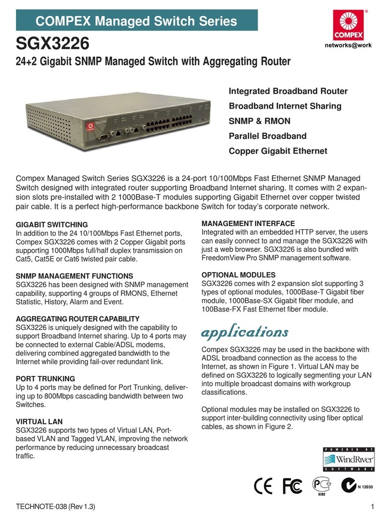
Compex SGX3226 User manual

Compex
Compex SAS2224 User manual

Compex
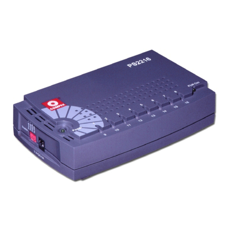
Compex PS2216 User manual

Compex
Compex SGX3226 User manual

Compex
Compex MicroHub TP1006C User manual
Compex
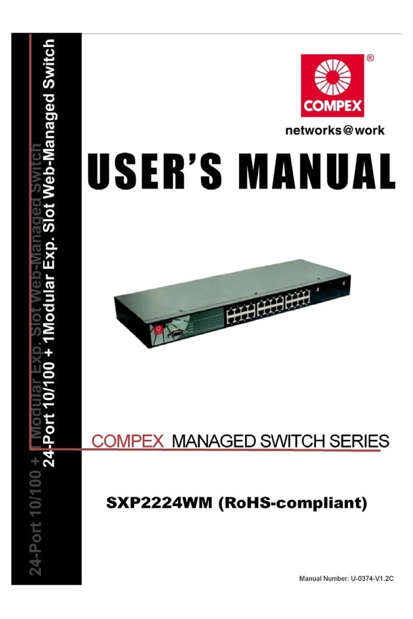
Compex SXP2224WM User manual
Compex
Compex readylink CGX3224 User manual

Compex
Compex Runner User manual

Compex
Compex readylink CGX3224 User manual