COMPU-FIRE 55560 User manual

024-55560
1
INSTALLATION INSTRUCTIONS
COMPU-FIRE® 3 PHASE CHARGING SYSTEMS
(Evo Big Twin Engines)
Part # 55560 Evo Big Twin with wet primary. Inc. vented rotor.
Part # 55570 Evo Big Twin w/ open primary. Inc. rotor w/o vents.
READ THESE INSTRUCTIONS COMPLETELY BEFORE BEGINNING
INSTALLATION!
NOTE: REFER TO THE FACTORY SHOP MANUAL ELECTRICAL SECTION FOR SAFETY
INSTRUCTIONS PRIOR TO PERFORMING ANY ELECTRICAL SYSTEM REPAIRS OR
MODIFICATIONS!
CAUTION! ALWAYS DISCONNECT THE BATTERY CABLES BEFORE PERFORMING ANY
ELECTRICAL SYSTEM REPAIRS OR MODIFICATIONS.THIS WILL PREVENT DAMAGE TO
THE ELECTRICAL SYSTEM OR COMPONENTS IN CASE OF AN ELECTRICAL ARC
CAUSED BY SHORTING THE BATTERY POWER TO GROUND.
WARNING! SEVERE DAMAGE TO THE ELECTRICAL SYSTEM OR PERSONAL INJURY
MAY OCCUR BY NOT FOLLOWING THE ABOVE SAFETY INSTRUCTIONS.
CAUTION! The installation of the Compu-Fire 3-Phase Charging System requires factory Harley
Davidson® service tools in the disassembly of the clutch and primary chain sprocket. If you are
not familiar with the disassembly of the primary drive assembly, or do not have the proper tools,
Compu-Fire recommends the installation be performed by a trained Harley Davidson®
technician.
1. Disconnect the cables at the battery. Remove the ground (-) cable first and then the
positive (+) cable.
2. Drain the oil in the primary chain case and remove the outer primary cover,
compensating sprocket, primary drive and clutch as described in the factory manual.
3. Remove the alternator rotor using Harley Davidson® puller part no. 95960-52B. Note
the location of the washers. Discard the washer on the inside of the rotor.
4. Remove the stator plug retainer and the four Torx head screws attaching the stator.
5. Remove the sprocket shaft seal and spacer following the factory service manual
instructions.

024-55560
2
6. Install a new sprocket shaft seal following instructions in the H-D service manual.
Install the Compu-Fire flanged seal spacer. NOTE: Lubricate the seal and the seal
surface of spacer with motor oil prior to installation.
7. Install the Compu-Fire 3 Phase stator using new fasteners (H-D Part no. 2720).
Torque the mounting screws to the specs in the service manual. NOTE: Make sure
the cable from the stator is routed so it does not pinch between the stator and
the case, and so that the rotor does not rub it. Install the stator plug retainer.
CAUTION! The Compu-Fire 3 Phase alternating rotor must only be used with the 3 Phase stator
supplied in the kit. Do not use the 3 Phase rotor with any other 40 amp wide stators. Do not use
the 3 Phase rotor as a replacement for Compu-Fire 40 amp charging systems part no. 55515,
55550, or 55555.
WARNING! The Compu-Fire 3 Phase rotor uses extremely strong magnets that may be
damaged if the rotor is placed near any metal parts, tools, or hardware in the work area.
WARNING! Special tools are required in the installation of the rotor. The Compu-Fire 3 Phase
rotor uses extremely strong magnets that may cause the installer to lose hold of the rotor during
installation. Severe injury may occur if the installer’s fingers become pinched between the rotor
and the engine case or the stator during installation. Use H-D tool P/N 41771 or Jim’s tool P/N
758-147 when installing the rotor.
8. Install the rotor on the crank shaft using H-D installation tool part no. 41771. NOTE:
The rotor will be vented in closed primary systems to allow additional cooling of the
stator. Open primary systems will use an unvented rotor. Refer to Figure 1.
COMPONENTS SUPPLIED IN THE COMPU-FIRE 3 PHASE SYSTEM
1. Large Flanged Seal Spacer
2. Alternating rotor (vented shown for wet primary systems)
3. Spacer washer (2.81 in. O.D. x .219 in. thick) except Softail/Dyna

024-55560
3
9. Re-install the primary drive assembly per factory service manual instructions.
10. Check the sprocket alignment per factory service manual instructions. Torque the
compensating nut to the engine manufacturer’s specifications. NOTE: Use Loctite
262 (red) on the threads of the compensating nut.
11. Re-install the primary cover using a new gasket and fill the primary case with the
correct amount of oil.
12. Attach the Compu-Fire 3 Phase Voltage Regulator to the frame. NOTE: The voltage
regulator must be mounted in an area with good air flow. Install the three wire
connector on the stator wires. NOTE: Stator wires have no polarity. Connect it to the
voltage regulator. Route the wires marked (+) and (-) to the battery. CAUTION! Use
the wire ties supplied to secure the wires to the frame. Make sure the wires cannot
come in contact with the exhaust system or become pinched between moving parts.
13. Connect the (+) wire from the voltage regulator to one side of the fuse holder. Do not
shorten the (+) wire or change the factory-crimped terminal. NOTE: If the cable is too
long, it must be coiled up and secured in the battery compartment. Do not shorten
the cable or change the terminal. Connect the other side of the fuse holder to the (+)
terminal of the battery. Connect the wire marked (-) to the (-) terminal of the battery.
Install the 40 amp fuse.
14. Reconnect the battery cables removed in step 1. Start the engine and allow it to
warm up to where it will idle. Verify the correct charging system output.
ORIGINAL EQUIPMENT COMPONENTS
4. Shaft extension
5. Compensating sprocket
6. Sliding cam
7. Compensating sprocket cover
8. Shim washer (varying thickness)
9. Compensating nut.

024-55560
4
TROUBLESHOOTING TIPS…
NOTE: The Compu-Fire Voltage Regulator uses high efficiency series type circuitry. The
electronic circuitry is different from O.E. and the trouble shooting procedure is different. Do not
use the test procedures found in the H-D factory shop manual, as the test will not be conclusive.
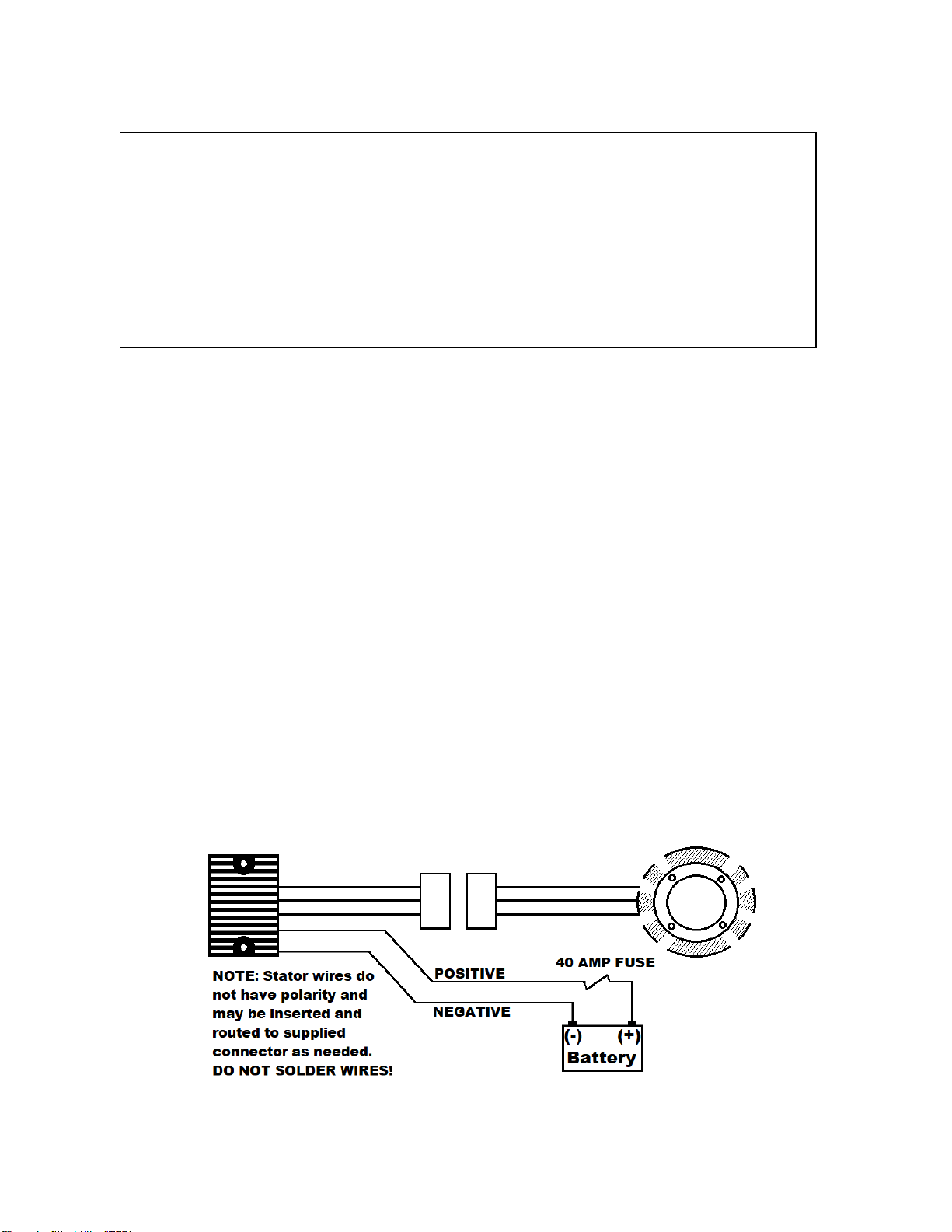
Stator
1. Has 3 Pins, each pin should have continuity to each other, but no pin should have continuity to
ground. (Imagine they are labeled A,B, and C. All combinations are AB, AC, and BC)
2. Each Phase (Ab, AC, & BC) should be putting out 14 volts AC, per 1,000 RPM.
(Check at 1,000 and 3,000 RPM)
3. If all this test out properly your installation of the stator was successful.
Regulator
1. With the ignition switch turned to the OFF position, measure the voltage across the battery.
The reading should be 12 to 13 volts DC. If there is no reading, the battery is either not
properly connected or the battery is dead.
2. Start the engine and raise the RPM to 1500. The voltage reading at the battery should
increase ½ to 1 volt to indicate the regulator is charging.
NOTE: Compu-Fire Products are manufactured and inspected under strict procedures specified
in the Compu-Fire Quality Assurance Program and are packaged and shipped in specially
designed boxes to insure against damage. Therefore, Compu-Fire will not accept any rotors
returned with chipped or broken magnets as the cause of this can only be due to careless
handling or improper installation techniques.
For technical assistance call 909/547-9058
PerTronix, LLC.
440 E. Arrow Hwy.
San Dimas, CA 91773
LIMITED WARRANTY
PerTronix, LLC. Warrants to the original Purchaser of its solid-state ignition system (product) that the module,
trigger rotor and wiring (components) shall be free from defects in material and workmanship for a period of (12)
months from the date of purchase.
If within the period of the foregoing warranty PerTronix finds, after inspection, that the product or any component
thereof is defective, PerTronix will, at its option, repair such products or component or replace them with identical
or similar parts PROVIDED that within such period Purchaser Promptly Notifies PerTronix, in writing, of such defects.
This manual suits for next models
1
Table of contents