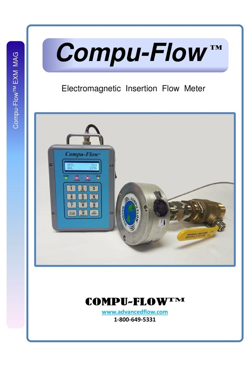
Compu-Flow C6 User manual

Operator’s Manual
Rev 1.6.1
Compu-Flow™ C6 Doppler Ultrasonic Flow Meter

DISCLAIMER AND LIMITATION OF LIABILITY
Compu - Flow™ Doppler Ultrasonic Flow Meter
COPYRIGHT
The information contained in this manual is subject to change without prior notice.
Compu-Flow™ makes no warranty of any kind whatsoever, either expressed or implied,
with respect to the information contained herein. Compu-Flow™ shall not be liable for
damages, of whatever kind, as a result of the reliance on or use of the information
contained herein.
INTERPRETING THE MANUAL
The following sections explain the document type conventions and the danger, warning,
and caution boxes that provide information about the specific levels of hazard
seriousness.
TYPE CONVENTIONS
Please note the following type conventions:
• Pin and signal names appear in capitalized italics (POWER_ON).
• New terms appear in italicized text.
• Unit labels (switches, indicators, and so on) appear in boldface text (ECHO).
• Commands (162) and command names (set point) appear in boldface, lowercase text.
CAUTION AND ATTENTION BOXES
This symbol represents important notes concerning potential harm to people, this unit, or
associated equipment. Compu-Flow includes this symbol in Warning, Caution, and Attention
boxes to identify specific levels of hazard seriousness.
iii
This manual and the information herein is the proprietary property of Compu-Flow™.
No Part of this manual may be reproduced or copied without the express written
permission. Any unauthorized use of this manual or its contents is strictly prohibited.
Copyright© January 2010. All rights reserved.


Compu-Flow™ Doppler Ultrasonic Flow Meter
Table of Contents
Chapter 1: Introduction and Theory of Operation
Introduction ................................................................................................................. 1-1
Features of the Compu-Flow™ Doppler Ultrasonic Flow Meter ................. ....1-1
Components of the Compu-Flow™ Doppler Ultrasonic Flow Meter System….1-2
Electronics Enclosure and Display Panel ........................................1-2
Transducers and Cabling ......................................... ……………….1-2
Theory of Operation ..................................................................................................... 1-2
Sonic Reflectors ........................................................................................ ..….1-3
Accuracy ...........................................................................................................1-3
Summary ................................................................................................. ….....1-3
Applications ............................................................................................... ………….....1-4
Chapter 2: Installation and Operation
Before Installing the Unit .............................................................................................. 2-1
Unpacking the Unit ........................................................................................ 2-1
Included Equipment ......................................................................... 2-1
Tools Required for Installation ..........................................................2-2
Pre-installation Procedures and Checks ....................................................... .2-2
Determining if Your Process/Installation is Right for a Doppler Flow Meter ..................2-3
Assessing Particles or Air Bubbles ................................................................. 2-4
Fluctuations in Flow Content ............................................................ 2-4
Process Changes ..............................................................................2-4
Assessing Pipe Material and Condition ..................................................... …..2-5
Assessing Flow Profile ................................................................................... .2-5
Straight Run Requirements ...............................................................2-5
Transducer Placement ......................................................................2-7
Compu-Flow™ Transit Time Ultrasonic Flow Meters ................................ …..2-9
Installation Procedures ................................................................................. …………..2-9
Mounting and Connecting the Transducers .................................................... 2-9
Mounting and Connecting Power to the Electronics Enclosure .....................2-13
Operation .............................................................................................................. ..….2-15
Display Panel ................................................................................................ 2-15
LEDs ........................................................................................... ....2-16
First Time Operation ..................................................................................... 2-17
If You Experience Unstable Readings .............................................2-20
Advanced Configuration Options ............................................................. …..2-20
Primary and Secondary Keyboard Functions …………………………………………… .2-21
Before Setting Advanced Parameters .............................................2-22
Setting Advanced Parameters .........................................................2-22
Normal Operation .................................................................................... .…2-25
Portable Battery Operation (Portable Units Only) .........................................2-25
v

Chapter 3: Troubleshooting and Customer Support
Troubleshooting the Unit .............................................................................................. 3-1
Flow Meter Troubleshooting Tables ............................................................... .3-2
Status of Unit Power .........................................................................3-2
Status of Echo LED: Off ....................................................................3-3
Status of Echo LED: Flashing ...........................................................3-5
Status of Flow Reading: High or Low ........................................... …3-6
Status of Flow Reading: Erratic .................................................... ....3-8
Additional Troubleshooting Information .............................................................3-9
Echo LED Light Considerations .........................................................3-9
Suspended Particle Test For Doppler Signals ............................... ..3-10
Compu-Flow™ Systems Support ..................................................................................4-15
Returning Units for Repair .............................................................................................3-12
Warranty ........................................................................................................... ……….3-12
Authorized Returns ......................................................................................... .3-13
Warranty Statement ................................................................................ ……..3-13
Chapter 4: Specifications and Reference Information
Performance Specifications ...........................................................................................4-1
Physical Specifications ..................................................................................................4-2
Functional Specifications .................................................................................. ……….4-3
Dimensional Drawings ................................................................................. …..…..…..4-6
Electronics Enclosure Dimensions ...................................................... ..………4-6
Clamp-On Transducer and Digitizer Dimensions ..............................................4-8
Reference Information ................................................................................................. .4-8
Standard Pipe Data .......................................................................................... 4-9
Velocity Conversion Tables .......................................................................... ..4-12
vi

• Wireless Signal option from Sensors and/or Receiver (sensor singular)
Chapter
1
Introduction and Theory of
Operation
INTRODUCTION
The Compu-Flow™ Doppler ultrasonic flow meter provides an accurate and easy-to-use
measuring system for high-solid fluid flow through pipes 0.50 inch to 999 inches
(inside diameter). The Doppler flow meter is well suited for flow measurement
applications such as sludges, slurries, aerated liquids, sewage, dredges, pulp, plastics,
and activated sludges. The Doppler flow meter features clamp-on transducers and a
rugged NEMA 4X enclosure, and is a long-term, maintenance-free solution for your
high-solid flow measurement requirements.
Features of the Compu-Flow™ Doppler Ultrasonic Flow Meter
The Doppler flow meter features:
• AC or DC operation, Isolated, Regulated, Module
• Smart LCD screen featuring high-resolution, 32 character, 2-line alphanumeric
providing rate and totalization simultaneously—in Metric and English units
• Splash proof NEMA 4X case protected from moister and caustic chemicals
• Easy configuration for set up and operation with on-screen prompting, quick
scrolling menus, display panel keypad, and color coded LEDs
• Non- invasive, Submersible, Clamp-on transducers
• RS232 via DB9 PORT 9600 Baud
• Separate High and Low Alarm outputs for Dry Contact Relay with LED status
• Optional signal cable lengths up to 5000 ft. No Tuning required.
• High accuracy even in turbulent flows
• Wide pipe diameter range 0.50 - 999 inches
• Maintenance-free modular construction simplifying field service
Introduction and Theory of Operation
1-1
• Data Logger 1 – 32 GB memory USB Flash Drive data transfer
• Batch Control, Isolated Output for Dry Contact Relay

Components of the Compu-Flow™ Doppler Ultrasonic
Flow Meter System
A typical Doppler flow meter system is comprised of an electronics enclosure, with a
display panel, and two clamp-on transducers.
ELECTRONICS ENCLOSURE AND DISPLAY PANEL
The display panel in the electronics enclosure features an easy-to-read LCD screen, a
keypad, and LEDs to interface with the flow meter. The Doppler flow meter can be
wall mounted for permanent installation or a portable option is also available.
TRANSDUCERS AND CABLING
The Doppler flow meter is configured with clamp-on transducers. When installed, the
sensors gather fluid flow data through a pipe and send this information to the system
electronics. The electronics then convert, transmit, and display the received data.
The clamp-on transducers allow you to install the Doppler flow meter without shutting down flow
and are ideal for smooth, clean pipe walls. The transducers are NEMA 6-rated and fully
submersible. Contact “Compu-Flow Systems Support” on page 4-15 for information on configuring
your meter for continuous submersion.
The standard cable length between the electronics enclosure and the transducers is 25
feet. Custom cable lengths up to 5000 feet are available. Wireless Sensor to Display where
applicable. See “Compu-Flow Systems Support” on page 4-15 for contact and ordering
information.
THEORY OF OPERATION
The Compu-Flow™ Doppler ultrasonic flow meter measures flow velocity by sensing
signals from reflective materials within a liquid and measuring the frequency shift due
to the motion of these reflective materials. The Doppler effect states that the received
frequency is a function of the transmitted frequency and the relative motion between
transmitter and the receiver.
The classic example of the Doppler effect is the train whistle increasing in pitch to the
listener at the station as the train approaches, then decreasing in pitch as the train
moves away from the station. To the person riding on the train, the pitch remains the
same. The increasing pitch is due to phase-front compression and the decreasing pitch
is due to phase-front expansion. The Doppler flow meter uses this effect to measure
the velocity of a liquid through a pipe wall.
1-2
Introduction and Theory of Operation

Compu-Flow™ Doppler Ultrasonic Flow Meter
Sonic Reflectors
The Doppler flow meter requires sonic reflectors in order to operate. These reflectors
may consist of particles or air bubbles within the flow to be measured. Your readings
may vary slightly with changes in concentration or size of these reflectors as well as
the pipe condition and size.
Note: Glycerin is the only known industrial liquid today that is not sonically
conductive.
The Doppler flow meter uses two similar transducers to sense flow in a pipe. These
transducers are mounted on the outside of a pipe. This configuration presents no
obstruction to flow, and will not cause associated pressure drops.
Accuracy
The Doppler flow meter output signal is linear (as opposed to square root), which
means that accuracy is not a function of flow rate. Within certain application limits,
the meter is ideal because it is not affected by changes of pressure within the process
nor by changes of viscosity, temperature, specific gravity, sound velocity, or electrical
conductivity.
Summary
The Doppler flow meter is a non-intrusive flow meter system which operates by
sensing the frequency shifts of signals reflected from particles, air bubbles, or density
differences within a liquid, producing a linear signal proportional to the flow of the
liquid within the pipe.
• No pipe section is required to install the meter.
• The meter is not affected by changes in temperature, viscosity, specific gravity, or
the speed of sound within the liquid.
• The liquid does not have to be electronically conductive.
• A minimum particle concentration of 35 ppm @ 40 micron of suspended solids or
air bubbles is required.
• The reflector must have at least a 0.2% density difference than the liquid medium.
• For accurate volumetric measurement the pipe must be full at all times.
• The transducers are normally coupled to the outer pipe wall with greaser, sonic gel or epoxy.
• In order to obtain accurate measurements adequate upstream and downstream
pipe runs are required. Recommended straight-run requirements from any
disturbance of flow are 10 diameters upstream and 20 diameters downstream.
Introduction and Theory of Operation
1-3

APPLICATIONS
Some of the materials the Compu-Flow™ Doppler ultrasonic flow meter is well-suited
for measuring include:
•
•
•
•
•
•
•
•
•
•
•
•
•
•
•
•
•
•
•
•
Ag water
Abrasives
Asphalts
Concrete
Dredge flows
Drilling mud
Large contaminates
Extremely viscous substances
Grout
Hazardous wastes
Municipal sludges and wastes
Paper pulp
Rendering products
Reservoirs
Rivers and streams
Runoffs
Sludges
Slurries
Suspended solids
Most all liquids containing suspended particles or air bubbles
1-4
Introduction and Theory of Operation

Chapter
2
Installation and Operation
BEFORE INSTALLING THE UNIT
Before installing your Compu-Flow™ Doppler ultrasonic flow meter,
follow the steps listed below:
1. See “Unpacking the Unit” on page 2-1.
2. Make sure you have performed the --“Pre-installation Procedures and Checks” on
page 2-2.
3. Determine if your process/installation is compatible with the requirements of
Doppler flow meter. See --“Determining if Your Process/Installation is Right for a
Doppler Flow Meter” on page 2-3).
4. Proceed to “Installation Procedures” on page 2-9.
Unpacking the Unit
Unpack and inspect the unit carefully, looking for obvious physical damage. If no
damage is apparent, locate and save all documentation and then continue with the
following procedures.
If you see signs of shipping damage, contact your supplier for product support.
(see “Compu-Flow Systems Support” on page 4-15 for contact information). Save the
shipping container for submitting necessary claims to the carrier.
INCLUDED EQUIPMENT
Table 2-1 lists the standard items that ship with Compu-Flow™ Doppler Ultrasonic
Flow Meter systems.
Installation and Operation
2-1

• Tape measure to measure pipe size
Table 2-1. Items shipped with the flow meter system
Dedicated unit (C6D model)
• Electronics enclosure
• Two transducers and a 25´ cable std.
* 100/240VAC/12VDC@300mA Reg Supp.
• Sensor Strap Kit
• Sonic coupling gel
• User manual
Portable unit (C6P model)
• Electronics enclosure
• Two transducers and a 25´ cable std.
• Sensor Strap Kit
• Sonic coupling gel
• User manual
• 12 V 1.0 AH battery nominal
• Smart 100/240VAC battery charger
• Auxiliary transport handle
•Padded Field transport case
TOOLS REQUIRED FOR INSTALLATION
• Sandpaper to clean the pipe surface to bare pipe
Custom lengths up to 5000’ (min 25’ adder)
Pre-installation Procedures and Checks
Before you install your Doppler flow meter, there is a pre-install check you should
perform to ensure that this is the appropriate meter to use for your application. If you
encounter any difficulties during the pre-installation procedures, see “Determining if
Your Process/Installation is Right for a Doppler Flow Meter” on page 2-3 before
proceeding with the installation process.
To Perform the Doppler flow meter Pre-installation Check:
1. Mount the transducers side by side between 7 o’clock and 10 o’clock on the pipe
(see “Mounting and Connecting the Transducers” on page 2-9 for more
information).
2. If not already connected, connect the transducers to the electronics enclosure (see
“Mounting and Connecting the Transducers” on page 2-9).
3. Connect AC or DC power to the flow meter (see “Mounting and Connecting
Power to the Electronics Enclosure” on page 2-13).
4. Turn on the power using the switch on the display panel.
5. After the electronics enclosure powers up and the front display panel lights up,
press soft key 1 to select FPS (feet per second).
6. Estimate your expected flow rate and compare it to the reading in feet per second
on the display panel.
2-2
Installation and Operation

Compu-Flow™ Doppler Ultrasonic Flow Meter
If the reading on the display appears to be accurate, continue to the next step.
If you do not see a flow reading on the LCD screen at all, or if the flow reading
is much lower or higher than expected, try repositioning the transducers. If this
does not help, see “Determining if Your Process/Installation is Right for a
Doppler Flow Meter” on page 2-3 and consult “Troubleshooting the Unit” on
page 3-1.
7. Observe the yellow Echo LED on the display panel.
If the Echo LED is on steady, and the flow reading appears to be accurate, your
Doppler flow meter is ready for operation. See “Normal Operation” on
page 2-25 to configure the flow meter for operation with your system.
If the Echo LED is flashing or not illuminated, see “Determining if Your
Process/Installation is Right for a Doppler Flow Meter” on page 2-3 and
consult “Troubleshooting the Unit” on page 3-1.
DETERMINING IF YOUR PROCESS OR
INSTALLATION IS RIGHT FOR A DOPPLER
FLOW METER
Accurate operation of a Doppler flow meter depends upon your application and
installation site. Doppler flow meters offer many advantages over other flow meter
models when flows are viscous, turbulence is minimal, and piping materials are
appropriate. When conditions are adverse to Compu-Flow™ Doppler ultrasonic flow
meter operation, the Compu-Flow™ Transit Time flow meter may offer an excellent
alternative. Contact “Compu-Flow Systems Support” on page 4-15” for more
information about this transit time meter.
To determine which flow meter is appropriate for your process and specific
installation, consider the following:
• The presence of reflective particles in the flow
• The pipe material and condition of pipe housing the flow
• The flow profile, meaning that you are able to provide acceptable straight run
requirements to ensure more accurate readings
The following sections discuss these considerations.
Installation and Operation
2-3

Assessing Particles or Air Bubbles
The ultrasonic beam from the transducer is transmitted through the pipe wall into the
liquid. The particles, air bubbles suspended in the liquid, have to be large enough to
act as reflectors to return the signal back to the transducer so that a measurement may
be taken. It is important to understand that the ultrasonic beam from the Doppler flow
meter does not penetrate air very well. A few bubbles will not affect flow meter
performance, but too many bubbles may cause the meter to malfunction. See
“Suspended Particle Test For Doppler Signals” on page 3-10 for information on how
to assess the particulate content of your flow.
Note: At a frequency of roughly 650 kHz, the minimum particle which can be sensed
is 40 microns @ 35 parts per million (ppm) and at least 0.2% density difference
from the liquid.
Attention:
The flow to be measured must always have a sufficient number of sonic
reflectors of ample size in order to provide reflection of the transmitted
sound. If the reflectors do not have sufficient density difference they
will neither rise nor fall in the solution but remain suspended. The
specific gravity will also affect the ability of a particle to reflect sound.
A good example of a reflector is a sand particle or an air bubble. A poor
example is algae or onion skins.
FLUCTUATIONS IN FLOW CONTENT
Wide fluctuations in flow suspended solids content can only be handled by an instrument
capable of monitoring such a wide fluctuation in liquid characteristics. Extreme cases may
require the use of both a transit time flow meter as well as a Doppler flow meter. For example,
river water may require a meter which is capable of measuring both clean and dirty liquids.
Depending on conditions, the river may vary considerably in suspended solid content. In this
situation contact your rep and ask about the Compu-Flow™ Hybrid System.
PROCESS CHANGES
Changes in the process may cause the meter to cease proper operation. For example, a
Doppler meter had been operating satisfactorily for a long time in a certain
installation, and then suddenly it stopped functioning. The problem was eventually
traced to a particle filter that had recently been placed before the transducers,
effectively eliminating the reflectors from the stream.
Process changes in the other direction are also possible. The meter responds to
bubbles up to a point, but if the liquid starts to foam there may be too many air
bubbles to allow the ultrasonic beam to adequately penetrate the flow stream. This
may cause the Doppler flow meter to produce erroneous flow readings. Similarly, a
sludge may become too dense to allow proper penetration.
2-4
Installation and Operation

Compu-Flow™ Doppler Ultrasonic Flow Meter
Assessing Pipe Material and Condition
Doppler flow meter performance is best maximized by using piping that is sonically
conductive. The Doppler flow meter assumes that the path by which the ultrasonic
beam enters the pipe and returns to the transducer is ultrasonically homogenous,
which means that you must use your flow meter with pipes with non-porous smooth
pipe walls. Concrete-lined pipes, old or crystallized cast iron pipes, hand-wrapped
fiberglass pipe, and old piping with air inclusions do not exhibit the required
homogeneity. Avoid using the Doppler flow meter for flow measurement on these
pipes unless proper operation is proven by the manufacturer through demonstration.
Contact “Compu-Flow Systems Support” on page 4-15 for more information on an
alternate meter if your application is not suitable for the Doppler flow meter.
Note: No clamp-on meter will operate properly if the liner is not solidly attached to
the pipe wall because of the probability of an air gap.
Pipe Vibration
Moderate pipe vibration does not usually adversely affect the Doppler flow meter,
since the vibration of the piping is at a significantly lower frequency than the
ultrasonic beam used to measure flow. However, in situations where the transducer
signal strength is low because of fluid, piping, or other environmental factors,
measurement accuracy may be further decreased by pipe vibration. In these situations
your display panel may register flow when there is none due to the vibration. If you
can not bracket the pipe to reduce vibration, you may be able to rectify the problem by
relocating the transducer to a pipe location with less vibration.
Assessing Flow Profile
STRAIGHT RUN REQUIREMENTS
As with other flow meters such as vortex or magnetic flow meters, the Doppler flow
meter needs a well-developed flow profile to ensure accurate flow measurement. To
assure a well-developed profile, choose a measurement point on a long run of pipe—
well away from elbows, valves, pumps, flanges, and other possible sources of
turbulence.
The ideal placement of the Doppler flow meter is with 20 diameters of straight run
upstream and 10 diameters of straight run downstream between the transducers and
any disturbance of the flow. Most typical flow meter applications use 10 diameters of
straight run upstream and 5 diameters downstream from any disturbance of the flow.
Installation and Operation
2-5

meter is not performing ideally. A point to remember is that turbulence is a non-linear
function of flow, so turbulence can create reflected signals. Interpret readings near
turbulent flows with caution.
Sources of turbulence are elbows, flanges, valves, orifices, wedges, pumps, pipe
openings, and pipe irregularities (rust, corrosion, and buildup). Try to avoid vertical
pipe runs (especially downhill pipe runs).
Table 2-2. Transducer distance from turbulence and reading accuracy
Accuracy is dependant on flow profile, and is related to the percentage of sound
reflectors and their size variation and distribution.
Figure 2-1 provides straight run examples.
2-6
Installation and Operation
Upstream
Downstream
%Accuracy
20 diameters
10 diameters
±1% to 3% of full scale
10 diameters
5 diameters
±3% to 5% of full scale
5 diameters
2 diameters
±5% to 10% of full scale
However, when the measured fluid is too clean to provide the proper number of
reflective particles, one may position the transducer near the pump or source of
turbulence in such a manner as to obtain stable readings in a continuous flow full pipe
situation. Using a transit time meter may be another viable option if the Doppler flow

Compu-Flow™ Doppler Ultrasonic Flow Meter
D = Nominal pipe diameter
Figure 2-1. Straight run examples
TRANSDUCER PLACEMENT
You should always avoid measuring liquids in vertical downward flows with any flow
meter. In the case of Doppler flow meters, vertical downward flows cause erroneous
readings by introducing air bubbles. Excessive air bubbles attenuate the measurement
signal by hampering penetration of the ultrasonic beam into the fluid. Bubbles will
tend to rise against the flow, and since the Doppler flow meter is capable of totalizing
in both directions, this will cause erroneous flow measurements as the meter factors in
the backward flow of the bubbles. Additionally, in vertical flows it may be difficult to
keep the pipe full, allowing pockets of air into the pipe. This will drastically reduce
the transducer’s ability to penetrate the flow and produce a readable signal.
Installation and Operation
2-7

When the Doppler transducers are mounted on a horizontal pipe, care should be taken
to mount them in the 7 o’clock to 10 o’clock positions (with the top of the pipe—the
side furthest from the Earth—corresponding to the 12 o’clock position). If the
transducer is mounted on the bottom of the pipe, settling particles may attenuate the
signals by introducing an additional sonic barrier. Also, air may agglomerate at the top
of the pipe. Since the ultrasonic frequencies used will not penetrate air efficiently, the
signal will be heavily attenuated so that the meter will not be able to render accurate
results.
Horizontal Pipe Mounting
The recommended placement of the Doppler transducers is a horizontal section of
piping. Figure 2-2 provides horizontal mounting examples.
Transducers
Figure 2-2. Horizontal pipe mounting examples
Vertical Pipe Mounting
Measuring flow at a vertical pipe run is not recommended. If measuring flow in a
vertical run can not be avoided, we recommend you measure at a point where the
direction of flow through the pipe is upwards to help ensure the pipe will remain full
at all times (Figure 2-3). However, measuring flow even with an upward vertical pipe
run will not address all the problems associated with this configuration.
Transducers
Figure 2-3. Vertical pipe mounting examples
2-8
Installation and Operation

Compu-Flow™ Doppler Ultrasonic Flow Meter
Compu-Flow™ Transit Time Ultrasonic Flow Meters
In the event the flow to be measured does not contain the minimum required particle
size and/or parts per million count, and the transducer will not read, you may want to
consider the Compu-Flow™ Transit Time ultrasonic flow meter for your application.
Contact your Compu-Flow™ sales representative with your application questions.
See “Compu-Flow Systems Support” on page 4-15” for contact information.
INSTALLATION PROCEDURES
After you have performed the pre-install check and determined that the Doppler flow
meter will work for your application, follow these steps to install your meter.
To Install the Compu-Flow™ Doppler Ultrasonic Flow Meter:
1. Mount and connect the transducers
2. Mount and connect power to the electronics enclosure (see page 2-13)
3. Turn on power to the electronics enclosure using the motherboard rear panel switch on the
(front panel for portable) and follow display panel for meter set up (see “Operation” on page
2-15 for more information on configuring your meter for operation)
Mounting and Connecting the Transducers
The clamp-on transducers are NEMA 6-rated and fully submersible.
(For continuous submersion secure sensors to pipe with approved epoxy.)
To Mount the Clamp-On Transducers to the Pipe:
1. Ensure the pipe surface is clean. Use sandpaper to remove all paint and scale from
the pipe surface if necessary.
2. Apply sonic gel to the transducer lenses. For best results in most weather
conditions and heat, use Dow Corning® High Vacuum Grease or the supplied
Novagard® grease G661™.
Attention:
Always apply sonic gel to the transducer lenses before placing on the pipe
The sonic gel must be used to transmit the energy from the transducer crystals
through the pipe wall and into the flow to be measured.
Installation and Operation
2-9

5. Small pipes below 2” function poorly with side by side mounting.
Pipes 2”-1” diameter – mount sensors 90° apart
Pipes below 1” diameter – mount sensors 180° apart

Note: Do not connect bare shield wire to black (common / ground)
Compu-Flow™ Doppler Ultrasonic Flow Meter
Figure 2-5. Clamp-on transducers secured with a bungee and chain
To Connect the Transducers to the Electronics Enclosure:
1. Ensure AC or battery (DC) input power is turned off.
2. Connect the transducer cable to the electronics enclosure by routing the cable
through the appropriate opening (see “Bottom view of the electronics enclosure”
on page 4-7 for location of cable access openings). Use a Nema 4Xcable gland and a
cable
backing nut to securely fasten the trasnducer cable to the electronics enclosure.
3. Connect the transducer wires to the processor board as shown in Figure 2-6 on
page 2-12 for correct placement. The transducer 4-wire connection is as follows:
White = Digital signal output (0 V to 12 V pulse train)
Green = Echo good logic signal (when used)
Red = 12 VDC at 100 mA nominal power in
Black = Ground / Common
Installation and Operation
2-11
Other manuals for C6
1
Table of contents
Other Compu-Flow Measuring Instrument manuals
Popular Measuring Instrument manuals by other brands

BEHA
BEHA Unitest CHB 4 instruction manual

Xylem
Xylem Bellingham+Stanley OPTi quick start guide

AquaLabo
AquaLabo PONSEL Supratec S200TUr owner's manual

Mirion Technologies
Mirion Technologies CheckPoint:Laundry RTM750 user manual

TA Instruments
TA Instruments AR 2000 Operator's manual

Kamstrup
Kamstrup MULTICAL 801 Installation and user guide