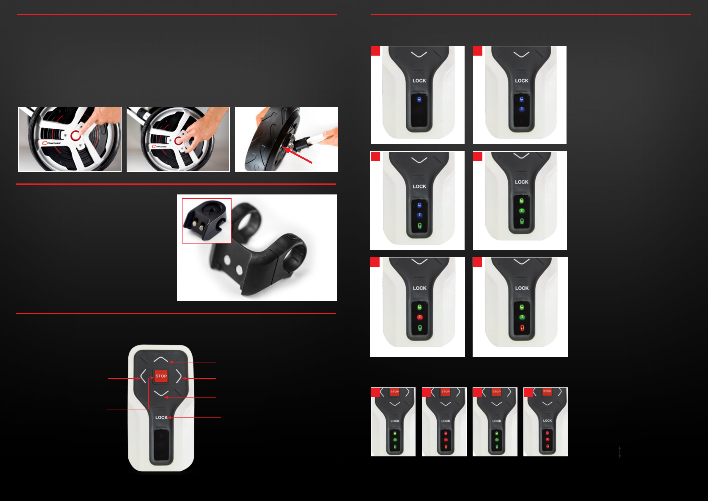
5.1 Position your buggy in a safe manner then remove the original
buggy wheels.
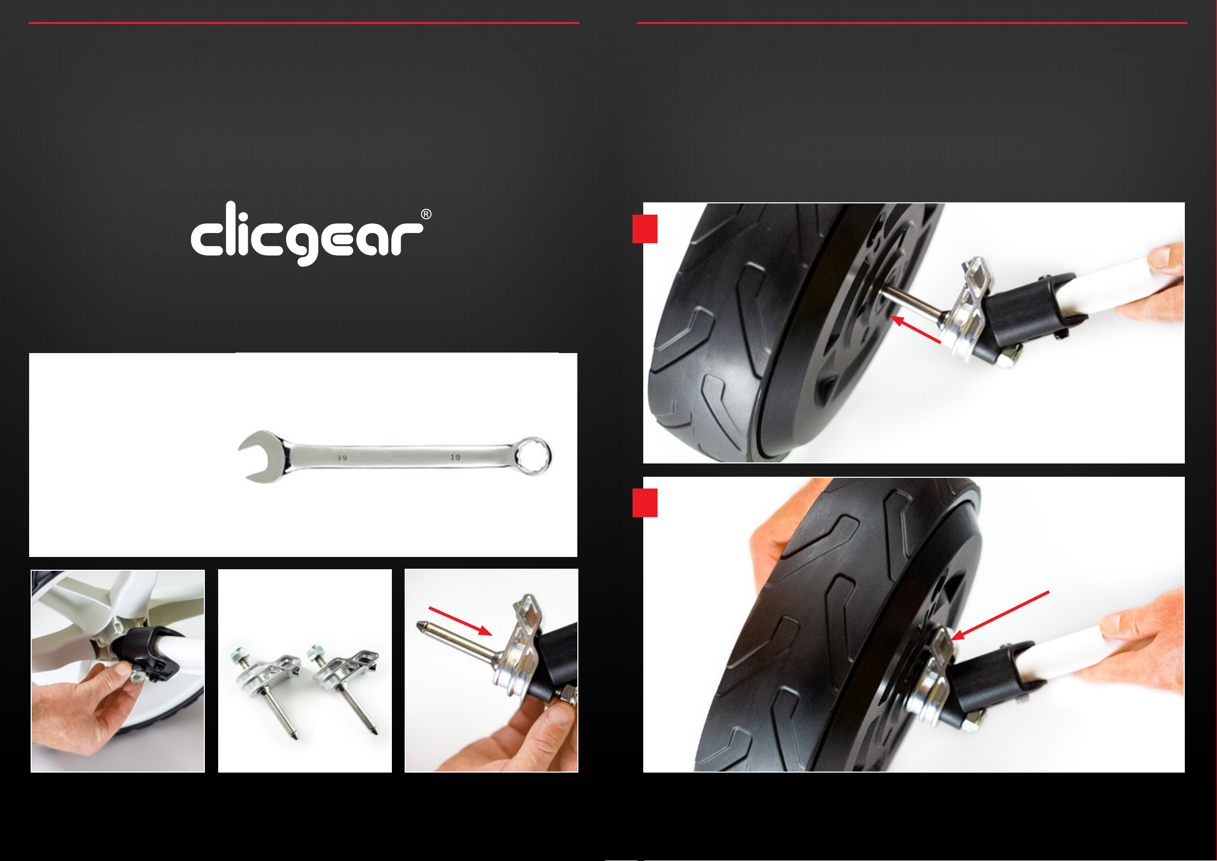
5.2 Locate the 2 small metal Smart Wheel Axles – Left and Right are
the same and fit on either side.
5.3 Connect both Smart Wheels axles to your existing push buggy
where you removed the original buggy wheels (as indicated
below).
Please ensure each firmly click into place, then pull on the axles
to test that they are secure.
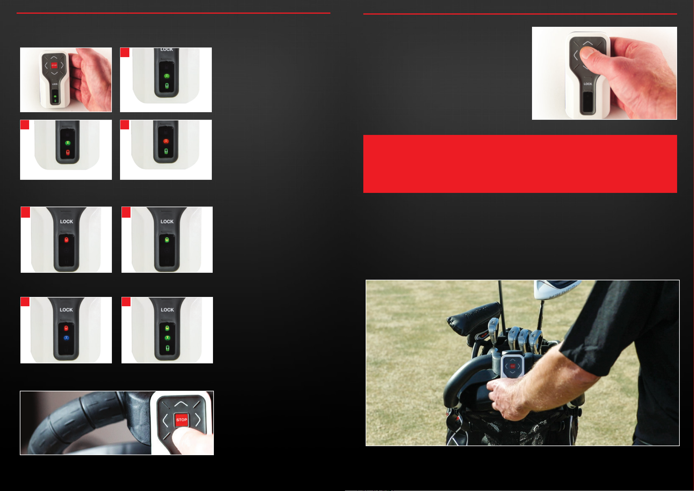
5.4 The Smart Wheels are labelled Left and Right.
Left and Right of the buggy is determined by standing behind
the buggy holding the handle as you would during play.
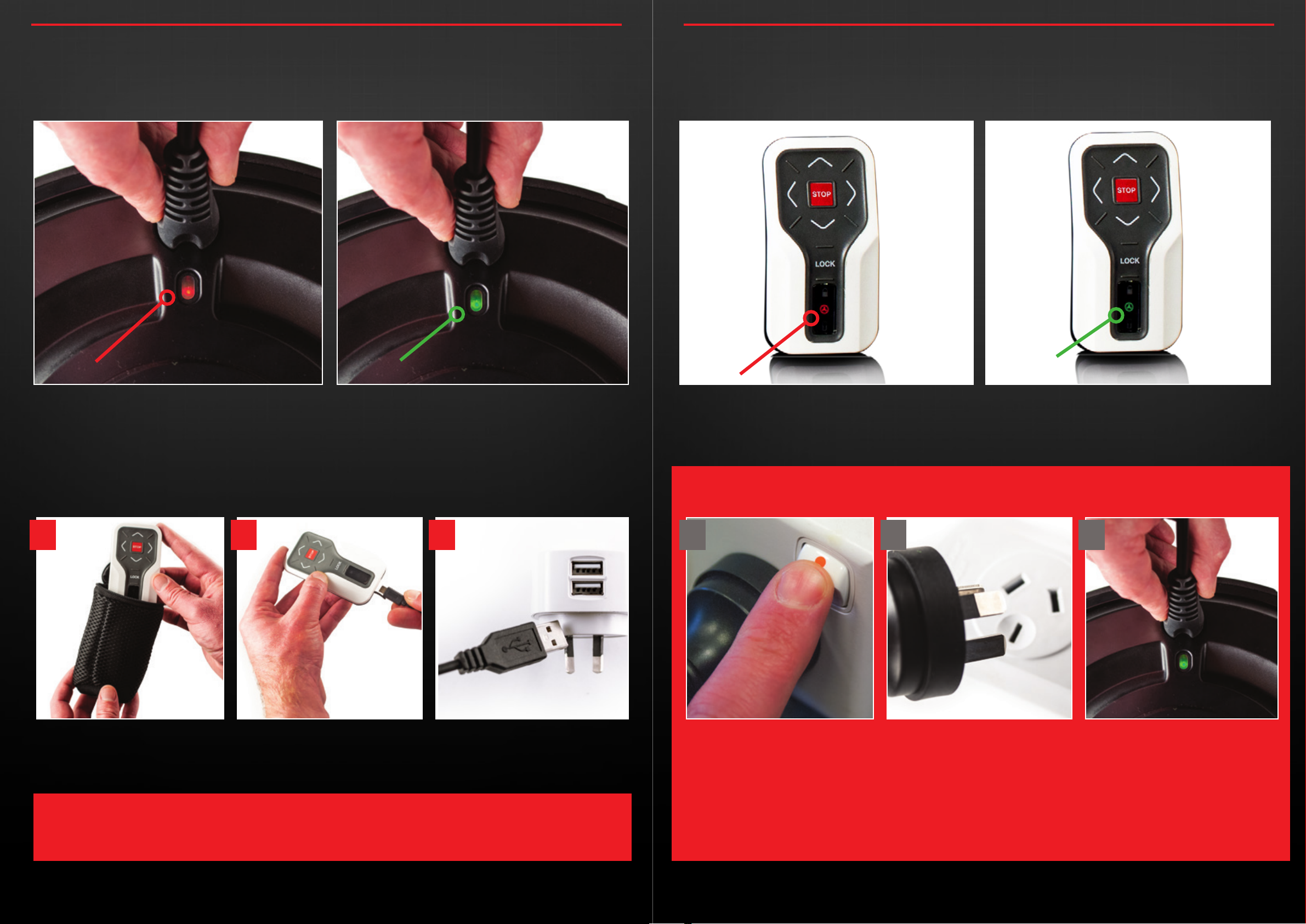
Now pick up one wheel and guide it onto the Axle already
connected to your buggy. To avoid excess dirt clogging the
charging socket it is recomended to position the charging
socket at the highest point from the ground as you slide the
wheel into positon. Press the red button on the outside of the
wheel as you guide it onto the axle. Release the red button
when the wheel is in position.
5.5 To ensure each Smart Wheels is securely locked in place you
may need to slightly rotate (up to ¼ turn) so the raised point
on outside of the axle neatly slots into the corresponding
indentation on the hub of the wheel.
This ensures the central hub of each Smart Wheel locks in place
and does not free-wheel.
Once both wheels are connected in the same manner they will
be able to drive the buggy.
5.0 CONNECTING THE SMART WHEELS TO OTHER MODELS
1 2
SECURELY LOCKED IN POSITION
4.0 CONNECTING THE SMART WHEELS TO YOUR CBM3 BUGGY
As an owner of the Concourse CBM3 Push Buggy you will not need to fit different axles (as opposed to other push buggy models).
The Smart Wheels will connect directly to the CBM3 axle, however, you do require locking pins to secure the central hub of the
Smart Wheels so the outer drives your buggy.
Before installing the CBM3 axle locking pins, please ensure you position your buggy in a safe and stable manner then remove the
two large free spinning wheels.
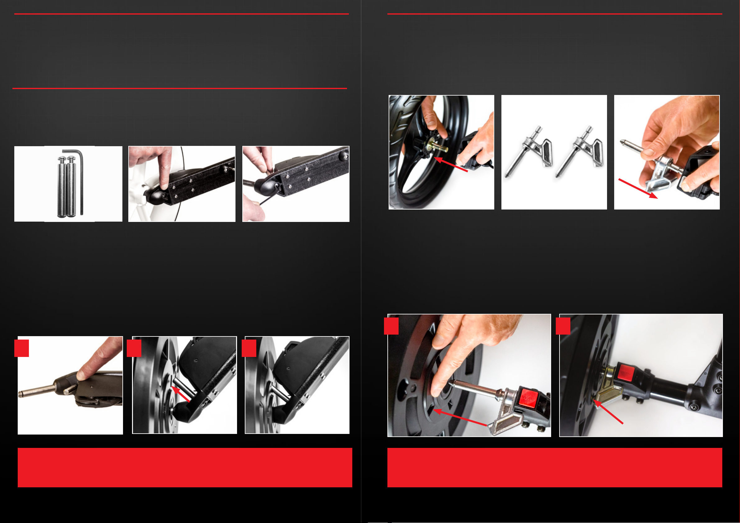
4.1 Enclosed you will find two locking pins and a 3mm allen key
as shown below.
4.2 You will notice a hole [also shown below] to thread the
locking pin screw through using the allen key.
4.3 Remove the original buggy wheels. Hold the locking pin,
then using the allen key thread the locking pin screw on
smoothly until it’s secure and tight. Repeat this process with
the opposite side of the CBM3 buggy.
4.4 The Smart Wheels are labelled Left and Right.
Left and Right of the buggy is determined by standing behind
the buggy holding the handle as you would during play.
Now pick up one wheel and guide it onto the Axle already
connected to your buggy. To avoid excess dirt clogging the
charging socket it is recomended to position the charging
socket at the highest point from the ground as you slide the
wheel into positon. Press the red button on the outside of the
wheel as you guide it onto the axle. Release the red button
when the wheel is in position.
4.5 To ensure each Smart Wheels is securely locked in place you
may need to slightly rotate (up to ¼ turn) so the raised point
on outside of the axle neatly slots into the corresponding
indentation on the hub of the wheel.
This ensures the central hub of each Smart Wheel locks in place
and does not free-wheel.
Once both wheels are connected in the same manner they will
be able to drive the buggy.
1 2
LOCKED IN POSITION
3
concoursegolf.com concoursegolf.com
10 11
User Instruction Manual | Version 6.0 User Instruction Manual | Version 6.0
CAUTION:
• PLEASE ALWAYS ENSURE WHEN ATTACHING OR REMOVING WHEELS FROM YOUR BUGGY IT IS SECURELY
SUPPORTED/HELD-UP, TO AVOID RISK OF INJURY OR EQUIPMENT DAMAGE.
PLEASE NOTE:
THE LOCKING PINS WILL SUIT EITHER SIDE OF THE BUGGY.