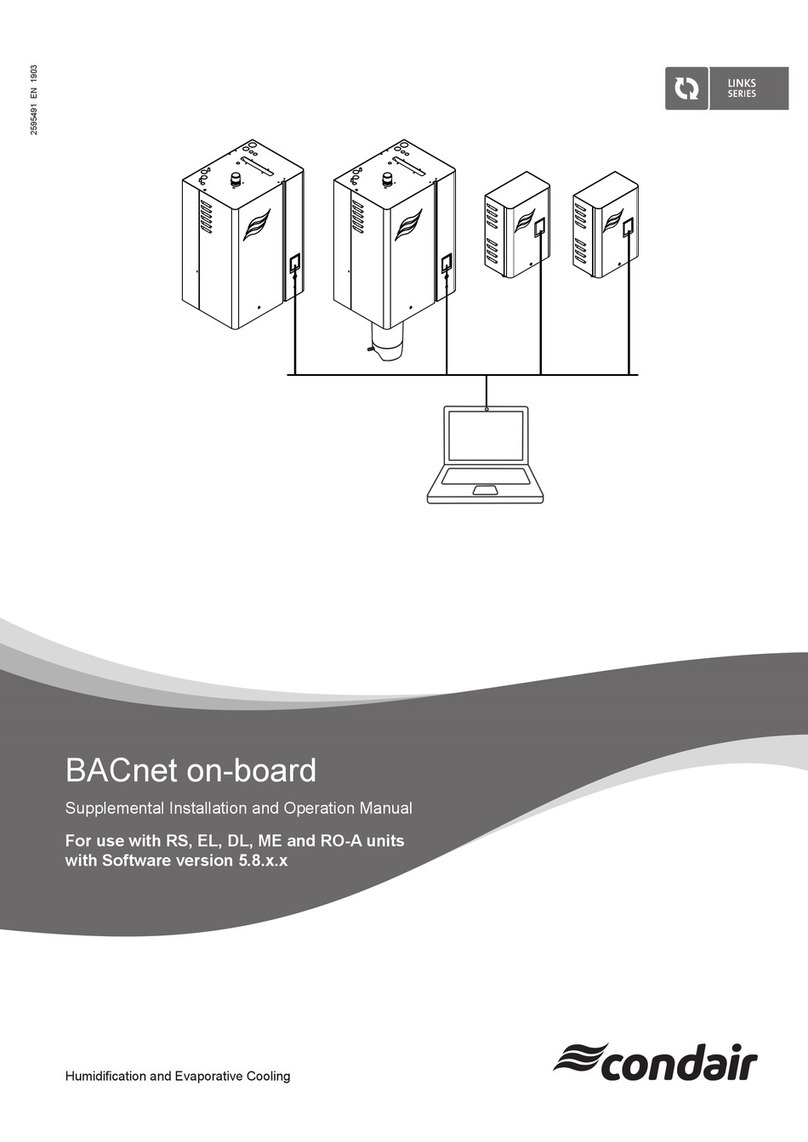
Condair Links Series User manual

2603582-0 EN 2112
Humidication and Evaporative Cooling
BACnet on-board
BACnet
Addendum manual for installation and operation
for use with DL II

Thank you for choosing Condair
Installation date (MM/DD/YYYY):
Commissioning date (MM/DD/YYYY):
Site:
Model:
Serial number:
Proprietary Notice
This document and the information disclosed herein are proprietary data of Condair Group AG. Neither this docu-
ment, nor the information contained herein shall be reproduced, used, or disclosed to others without the written
authorization of Condair Group AG, except to the extent required for installation or maintenance of recipient's
equipment.
Liability Notice
Condair Group AG does not accept any liability due to incorrect installation or operation of the equipment or due
to the use of parts/components/equipment that are not authorized by Condair Group AG.
Copyright Notice
© Condair Group AG, All rights reserved.
Technical modications reserved

3Contents
Contents
1 Introduction 4
1.1 Notes on this addendum manual 4
1.2 Functions overview 5
2 For your safety 6
3 Network integration via BACnet on-board 8
3.1 Notes for the planning engineer 8
3.1.1 Overview 8
3.1.2 Principle network diagrams 9
3.1.2.1 Principle BACnet network 9
3.2 Wiring 11
3.3 Conguration 12
3.3.1 Setup network parameters (or IP parameters) 12
13
3.3.2 Setup BACnet interface parameters 14
3.3.2.1 BACnet IP settings 14
3.3.2.2 BACnet MS/TP Einstellungen (Master oder Slave) 16
3.3.3 Signal settings and monitoring of bus communication 17
3.3.3.1 Setup control settings 17
3.3.3.2 Monitoring of bus communication 18
4 Communication tables 19
4.1 DL - BACnet on-board 19
4.2 Operating trouble list 22
5 Appendix 24
5.1 Object abbreviations 24
5.2 Declaration of Conformity for the implementation of BACnet protocols (PICS) 25
6 Ordering form 27

4Introduction
1 Introduction
1.1 Notes on this addendum manual
Condair devices equipped with an Integrated Controller can be connected via the corresponding interface
on the Integrated Controller (BACnet on-board) to a BACnet IP network or a BACnet MS/TP network.
This manual describes how to install and congure BACnet on-board (see Section 3) to connect Condair
devices with Integrated Controller to a building management system.
This addendum manual is intended for use by engineers and properly trained technical personnel. Please
read this manual thoroughly before working on the Integrated Controller.
If you have questions after reading this documentation, please contact your Condair representative.
They will be glad to assist you.
Symbols used in this manual
CAUTION!
The catchword "CAUTION" used in conjunction with the caution symbol in the circle designates notes
in this manual that, if neglected, may cause damage and/or malfunction of the unit or other mate-
rial assets.
WARNING!
The catchword "WARNING" used in conjunction with the general caution symbol designates safety
and danger notes in this manual that, if neglected, may cause injury to persons.
DANGER!
The catchword "DANGER" used in conjunction with the general caution symbol designates safety and
danger notes in this manual that, if neglected, may lead to severe injury or even death of persons.
Safekeeping
Please safeguard this addendum manual in a safe place, where it can be immediately accessed. If the
equipment changes hands, the documentation must be passed on to the new operator.
If the documentation gets mislaid, please contact your Condair representative for replacement.
Language versions
This addendum manual is available in various languages. Please contact your Condair representative
for information.

5Introduction
1.2 Functions overview
The following table gives you an overview of the supported protocols and functions.
BACnet on-board
Integrated controller
BACnet IP yes
BACnet MS/TP Master Mode yes
BACnet MS/TP Slave Mode yes
BTL certied yes
BACnet Service COV (Change of Value) yes
Please refer to the BACnet Protocol Implementation Conformance Statement (PICS, see Section 5.2)
and the objects tables (see Section 4) for detailed information.

6For your safety
2 For your safety
General
Every person working with the Condair Integrated Controller must have read and understood this ad-
dendum manual, and the installation manual and operation manual of the Condair Integrated Controller,
before carrying out any work.
Knowing and understanding the contents of the manuals is a basic requirement for protecting the person-
nel against any kind of danger, to prevent faulty operation, and to operate the unit safely and correctly.
All icons, signs and markings applied to the unit must be observed and kept in readable state.
Qualication of personnel
All work described in this addendum manual may only be carried out by specialists who are well
trained and adequately qualied and are authorised by the customer.
For safety and warranty reasons any action beyond the scope of this manual must be carried out only
by qualied personnel authorised by the manufacturer.
It is assumed that all persons working with the Condair Integrated Controller are familiar and comply
with the appropriate local regulations on work safety and the prevention of accidents.
Intended use
The BACnet on-board interfaces Condair Integrated Controller are intended exclusively for connecting
the Condair Integrated Controller to a BACnet based network. Any other type of application, without the
written consent of the manufacturer, is considered as not conforming with the intended purpose and
may lead to the Condair Integrated Controller becoming dangerous.
Operation of the equipment in the intended manner requires that all the information contained in this
addendum manual as well as in the installation manual and operation manual of the Condair
Integrated Controller are observed.
Danger that may arise from the Condair Integrated Controller
DANGER!
Risk of electric shock!
The control unit where the Integrated Controller is located is mains powered. Live parts may
be exposed when the control unit is open. Touching live parts may cause severe injury or
danger to life.
Prevention: Before commencing any work disconnect the corresponding Condair device from the
mains supply via the electrical isolator in the mains supply line, and secure electrical isolator in "Off"
position against inadvertent switching on.

7For your safety
Safety reporting
All persons working with the Condair Integrated Controller are obliged to report any alterations to the
system that may affect safety to the owner without delay and to secure such systems against ac-
cidental power-up.
Prohibited modications to the unit
No modications must be undertaken on the Condair Integrated Controller without the express writ-
ten consent of the manufacturer.
For the replacement of defective components use exclusively original accessories and spare parts
available from your Condair representative.

8Network integration via BACnet on-board
3 Network integration via BACnet on-board
3.1 Notes for the planning engineer
3.1.1 Overview
The BACnet on-board functionality of the Integrated Controllers allows to connect Condair devices via
the RJ45 Ethernet interface to a BACnet IP network or via the RS485 interface to a BACnet MS/TP
network without further options.
The following protocol options are available as standard:
Interface on the Integrated
Controller Protocol Description
RJ45 Ethernet port BACnet IP BACnet IP
RS485 interface BACnet MS/TP BACnet MS/TP Master or Slave Mode
Please refer to the BACnet object tables in Section 4 for detailed information regarding the available
read out and settings functions.

9Network integration via BACnet on-board
3.1.2 Principle network diagrams
3.1.2.1 Principle BACnet network
The principle diagram below shows the connection of the Condair Integrated Controller to a BACnet IP
network.
Principle BACnet IP network
Fig. 1: Principle BACnet IP network
3V
CR2032
JP8
X2
X1 X4 X5
X3
JP6
Ethernet (BACnet IP)
CAT6A cable (or higher) with
RJ45 termination
Integrated Controller
(back view)
RJ45
Important: When laying the network
cabling, make sure there is sufcient
distance to other cables, especially if
they are connected to the mains!

10 Network integration via BACnet on-board
Principle BACnet MS/TP network
The diagram below shows the connection of a Condair Integrated Controller to a BACnet MS/TP network.
The diagram also shows an application an application encountered in practice: BACnet MS/TP com-
municates with the higher-level BACnet IP via a router.
Fig. 2: Principle BACnet MS/TP network
3V
CR2032
JP8
X2
X1 X4 X5
X3
JP6
JP8
GND + –
GND
+
–
Ethernet (BACnet IP)
RS485 Network (BACnet MS/TP)
Shielded twisted-pair cable:
– 120 Ohm impedance
– Terminate shield at one end only
Integrated Controller
(back view)
RS485
BACnet MS/TP to BACnet IP
Router
Important: When laying the network
cabling, make sure there is sufcient dis-
tance to other cables, especially if they are
connected to the mains!

11Network integration via BACnet on-board
3.2 Wiring
1. Lead the network cable through a cable gland or the rectangular cable lead-through into the control
unit.
2. Connect network cable according to the following wiring diagrams to the corresponding interface
connector on the Integrated Controller.
BACnet IP BACnet MS/TP
3V
CR2032
JP8
X2
X1 X4 X5
X3
JP6
JP6
JP8
3V
CR2032
JP8
X2
X1 X4 X5
X3
JP6
JP8
GND + –
GND
+
–
JP6
JP8
Important: all devices must be connected to
each other via GND
Jumper settings:
Jumper JP6 and JP8 do not have any effect for
BACnet IP communication.
Jumper settings:
–Jumper JP6 must be set on the rst and
the last Integrated Controller in the network
(serves as terminating resistor at the start
and end of the network). Jumper JP6 set =
terminating resistor active.
– Jumper JP8 must be removed for the com-
munication via the RS485 interface X3.

12 Network integration via BACnet on-board
3.3 Conguration
After network wiring connections have been completed, the Condair Integrated Controller needs to be
setup to operate and communicate through BACnet IP or BACnet MS/TP with the building management
system. This setup includes the settings in the "Network" and the "Controls" submenu of the Integrated
Controller.
3.3.1 Setup network parameters (or IP parameters)
The network settings (or IP parameters) are required for communication via the integrated Ethernet
interface (RJ45).
Select "IP Settings" (Path: "Menu > Password: 8808 > Network > IP Settings"). The IP setting para-
meters appear.
01.09.2021DL
18:04
Home
Next Maintenance
1685 hr
Demand
Standby
0%
IP Settings
IoT Settings
Modbus Settings
BACnet Settings
01.09.2021DL
18:04
Network
01.09.2021DL
18:04
1001
Password
1 2 3
4 5 6
7 8 9
0
****
Network
01.09.2021DL
18:04
Menu
Maintenance
Features
Controls
01.09.2021DL
18:04
DHCP Mode
IP Address
Subnet Mask
Default Gateway
Secondary DNS
Host Name
Primary DNS
MAC Address
Primary DNS
DHCP
192.168.168.243
255.255.255.000
192.168.168.101
000.000.000.000
IC_2600000
192.168.168.001
FE:ED:AF:FE:BE:EF
000.000.000.000
IP Settings
– DHCP Mode: With this setting you determine whether the IP Address,
the Subnet Mask, the Standard Gateway as well as the Primary and Sec-
ondary DNS address should be assigned as xed values or dynamically
assigned via a DHCP server.
Note: If no address can be assigned via a DHCP server when "DHCP
Mode" is set to "DHCP", an APIPA (Automatic Private IP Addressing)
is automatically assigned. This is in the range from 169.254.1.0 to
169.254.254.255. The subnet mask is set to 255.255.0.0 and the standard
gateway remains 0.0.0.0.
Factory setting: DHCP
Options: DHCP (dynamic assignment)
Fixed (xed assignment)
– IP Address: This eld shows the actual IP address of the device assigned
manually or assigned by a DHCP server.
If the parameter "DHCP Mode" is set to "Fixed", the IP address of the
device can be set via this eld. If the parameter "DHCP Mode" is set to
"DHCP", the IP address of the device is assigned by a DHCP server.
– Subnet Mask: This eld shows the actual subnet mask of the IP network
assigned manually or assigned by a DHCP server.
If the parameter "DHCP Mode" is set to "Fixed", the subnet mask can be
set via this eld. If the parameter "DHCP Mode" is set to "DHCP", the
subnet mask is assigned by a DHCP server.

13Network integration via BACnet on-board
– Default Gateway: This eld shows the actual IP address of the default
gateway assigned manually or assigned by a DHCP server.
If the parameter "DHCP Mode" is set to "Fixed", the IP address of the
default gateway can be set via this eld. If the parameter "DHCP Mode"
is set to "DHCP", the IP address of the default gateway is assigned by a
DHCP server.
– Primary DNS: This eld shows the actual IP address of the primary domain
name server (DNS) assigned manually or assigned by a DHCP server.
If the parameter "DHCP Mode" is set to "Fixed", the IP address of the
primary domain name server can be set via this eld. If the parameter
"DHCP Mode" is set to "DHCP", the IP address of the primary domain
name server is assigned by a DHCP server.
– Secondary DNS: This eld shows the actual IP address of the secondary
domain name server (DNS) assigned manually or assigned by a DHCP
server.
If the parameter "DHCP Mode" is set to "Fixed", the IP address of the
secondary domain name server can be set via this eld. If the parameter
"DHCP Mode" is set to "DHCP", the IP address of the secondary domain
name server is assigned by a DHCP server.
– MAC Address: Factory set MAC Address (Media Access Control) of the
device. Not modiable.
– Host Name: Host Name of the device automatically generated by the
control. Format: "IC_"+"Serial number of the device". Not modiable.

14 Network integration via BACnet on-board
3.3.2 Setup BACnet interface parameters
Select "BACnet Settings" (Path: "Menu > Password: 8808 > Network > BACnet Settings"). The
BACnet setting parameters appear.
01.09.2021DL
18:04
Home
Next Maintenance
1685 h
Demand
Standby
0%
IP Settings
IoT Settings
Modbus Settings
BACnet Settings
01.09.2021DL
18:04
Network
01.09.2021DL
18:04
1001
Password
1 2 3
4 5 6
7 8 9
0
****
Network
01.09.2021DL
18:04
Menu
Maintenance
Features
Controls
3.3.2.1 BACnet IP settings
The following settings are required for BACnet communication via the integrated RJ45 interface.
01.09.2021DL
18:04
BACnet Protocol
Device Name
Device Description
Device Location
BACnet IP Port
BBMD IP Port
Node ID
Foreign Device
BBMD Re-Register Time
Node ID
BBMD IP Address
BACnet/IP
Condair Controller
Humidier
Technical room System 1
47808
47808
1001
On
10
1001
192.168.186.244
BACnet Settings
– BACnet Protocol: Set the "BACnet Protocol" parameter to "BACnet/IP"
to activate BACnet IP communication via the integrated RJ45 interface.
After changing this setting, the control automatically carries out a restart.
Factory setting: Off
Options: Off, MS/TP Master, MS/TP Slave or
BACnet/IP
– Device Name: With this setting you determine the name of the device for
the communication via the integrated BACnet interface.
Note: The name assigned here is also assigned to the object name of
the device object.
– Device Description: with this setting you determine a short description
of the device.
Note: The device description assigned here is also assigned to the property
"Description" in the device object.
– Device Location: With this setting you determine the designation of the
device location.
Note: The location assigned is also assigned to the property "Location"
in the device object.
– Node ID: With this setting you assign a node ID to the device for the
communication over the BACnet IP protocol. This ID must be unique in
the network.
Factory setting: 1001
Setting range: 1 - 4194303
– BACnet IP Port: With this setting you assign a IP port number for the
device. The default port for BACnet IP is 47808.
Factory setting: 47808
Setting range: 1 - 65535

15Network integration via BACnet on-board
– Foreign Device: With this setting, you determine whether the device logs
in to an external BACnet IP Broadcast Management Device (BBMD) ("On")
so that it can receive broadcast messages (messages to all participants)
on the IP network or not ("Off ").
Note: In an IP network, routers generally block broadcast messages
(messages to all participants) to reduce trafc. This prevents a BACnet
IP device from being detected via the "Who-is" service, or to answer via
the "I-Am" service. In order for the BACnet IP broadcast messages to
be forwarded to other network segments anyway, a BBMD (BACnet IP
Broadcast Management Device) is required. These devices integrated into
the IP network forward BACnet IP broadcast messages to other network
segments. Only one BBMD may be integrated per network segment.
Factory setting: Off
Options: Off or On
– BBMD IP Address: With this setting, you specify the IP address of the
external BBMD to which the device should log on.
– BBMD IP Port: With this setting you assign an IP port number to the
external BBMD.
Factory setting: 47808
Setting range: 1 - 65535
– BBMD Re-Register Time: With this setting you determine how long a
device remains registered with an external BBMD (BACnet IP Broadcast
Management Device) before a new registration is required.
Factory setting: 10
Setting range: 5 - 65535

16 Network integration via BACnet on-board
3.3.2.2 BACnet MS/TP Einstellungen (Master oder Slave)
The following settings are required for BACnet MS/TP Master or Slave communication via the integrated
RS485 interface.
01.09.2021DL
18:04
BACnet Protocol
Baud Rate
Device Name
Device Description
Node ID
Device Location
BACnet MS/TP MAC
Device Location
MS/TP Master
9600
Condair Controller
Humidier
1001
Technical room System 1
127
Technical room System 1
BACnet Settings
– BACnet Protocol: Set the "BACnet Protocol" parameter either to "MS/
TP Master" if the device is to act as the Master or to "MS/TP Salve" if
the device is to act as a Slave. After changing this setting, the control
automatically carries out a restart.
Factory setting: Off
Options: Off, MS/TP Master, MS/TP Slave or
BACnet/IP
– Baud Rate: With this setting you set the Baudrate for the data transfer..
Factory setting: 9600
Options: 9600, 19200, 38400, 57600, 76800, 115200
– Device Name: With this setting you determine the name of the device for
the communication via the integrated BACnet interface.
Note: The name assigned here is also assigned to the object name of
the device object.
– Device Description: With this setting you determine a short description
of the device.
Note: The device description assigned here is also assigned to the property
"Description" in the device object.
– Device Location: with this setting you determine the designation of the
device location.
Note: The location assigned is also assigned to the property "Location"
in the device object.
– Node ID: with this setting you assign a node ID to the device for the com-
munication over the BACnet MS/TP protocol. This ID must be unique in
the network.
Factory setting: 1001
Setting range: 1 - 4194303
– BACnet MS/TP MAC: with this setting you assign a MS/TP MAC address
for the device. This address must be unique in the network.
Factory setting: 127
Setting range: 0 - 127 (for Master)
0 - 254 (for Slave)

17Network integration via BACnet on-board
3.3.3 Signal settings and monitoring of bus communication
3.3.3.1 Setup control settings
By default the Condair Integrated Controller is congured to operate on a hardwired analog control signal
from an external humidity controller or a humidity sensor (if internal P or PI controller is used) connected
to the driver board inside the control unit.
Note: If you want the Condair Integrated Controller to be controlled via a hardwired analog control signal
set "Source" to "Analog" and set the other control settings as required (see "Operation Manual" of the
corresponding device for details).
If you want to control the Condair Integrated Controller via one of the integrated BACnet on-board inter-
faces the "Signal Settings" must be adjusted as follows.
Select "Signal Settings" (Path: "Menu > Password: 8808 > Controls > Signal Settings"). The setting
parameters for the signal transmission appear.
01.09.2021DL
18:04
Home
Next Maintenance
1685 h
Demand
Standby
0%
Signal Settings
01.09.2021DL
18:04
Controls
01.09.2021DL
18:04
1001
Password
1 2 3
4 5 6
7 8 9
0
****
Network
01.09.2021DL
18:04
Menu
Maintenance
Features
Controls
01.09.2021DL
18:04
Source
Control Mode
Signal Timeout
BACnet
Demand
300 s
1001
Signal Settings
– Source: Set "Source" parameter to "BACnet".
Factory setting: Analog
Options: Analog,Modbus,BACnet or IoT
– Control Mode: Set the "Control Mode" parameter to "Demand" (demand
signal from an external controller) or to "RH P" or "RH PI" (humidity signal
from an external humidity sensor).
Factory setting: Demand
Options: On/Off, Demand, RH P or RH PI
– Signal Timeout: With this setting you determine the timeout period for
the signal transmission. If communication with the BACnet system fails
for longer than the set time, warning "W35 - Signal Timeout" is triggered
and the Condair DL is stopped.
Factory setting: 300 s
Setting range: 1 ... 300 s
Important: If the demand or control signal via BACnet is used, no second, hard-wired demand or control
signal may be connected to the driver board!
Further information on the control settings can be found in the operating instructions for the correspond-
ing device.

18 Network integration via BACnet on-board
3.3.3.2 Monitoring of bus communication
The monitoring of the bus communication described below only takes place if the "Source" parameter
in the "Signal Settings" submenu is not set to "Analog" (siehe Section 3.3.3.1).
As soon as the control signal (demand or humidity signal) is transmitted via the BACnet IP or BACnet
MS/TP bus system, communication via the bus system is also monitored.
The control signal must be periodically updated within the time set in "Signal Timeout".
If the control signal is not updated within the set time, warning "W35 - Signal Timeout" will be triggered
and the humidication will be stopped until the device receives an updated value.
This monitoring is intended to prevent the humidier from humidifying with the last transmitted value in
the event of a bus failure.

19Communication tables
4 Communication tables
4.1 DL - BACnet on-board
Object Name Description Range Object-Type Object-ID Read (R)
Write (W)
Condair Controller Humidier –– DEV 1001 ––
Network Port IPv4 Network-Port for BACnet
IPv4 Communication –– Network Port 1R/W
Device Status Actual device status
1 = Initializing
2 = Diagnostic
3 = Stopped
4 = Flushing
5 = Standby
6 = Flushed
7 = Humidifying
8 = Ready
9 = Refreshing
10 = Air Pressure Cleaning
11 = Filling
12 = Conductivity Flush
13 = Switched Off
14 = Remote Off
15 = Regenerating
16 = Temperature Flush
17 = Ceramic Wash Over
MI 5154 R
Error Status Maintenance and error
status
1 = No Info
2 = Warning
3 = Activation Code
4 = Out of Commissioning
5 = Rell Disinfection
6 = Maintenance
7 = Error
8 = Replace Ag Cartridge
9 = Disinfection
MI 5155 R
DL Type Condair DL device
assembly conguration
1 = Humidier
2 = Humidier + FC
3 = Humidier + FC - Off
MI 5089 R
ErrorWarning Code Code of the latest pend-
ing error or warning 3) 0 = no Error AI 10020 R
Operating Hours Total hours of operation
since commissioning 0 - 1'200'000 h AI 10044 R
Next Maintenance Due date of next mainte-
nance in operating hours 0 - 10000 h AI 10060 R
Humidity Control Actual humidity or
demand 0 - 100 % AI 15068 R
Max. Hum. Capacity Maximum possible
spray water output 2)
2 - 1000 kg/h
4 - 2573 lb/hr AI 15172 R
Actual Hum. Capacity Actual spray water
output 2)
0 - 1000 kg/h
0 - 2573 lb/hr AI 15174 R
Remain. Ag-Ion
Capacity
Remaining Ag-Ion
capacity 0 - 58.4 Ah AI 15154 R
Target Ag-Ion Current Target Ag-Ion current 0 - 29.2 mA AI 15179 R
PS4 Inlet Pressure Inlet pressure PS4 2) 0 - 10.0 bar
0 - 145.0 psi AI 15170 R
PS5 Nozzle Pressure Nozzle pressure PS5 2) 0 - 10.0 bar
0 - 145.0 psi AI 15171 R
Water Temperature Inlet water
temperature 1) 2) °C or °F AI 15169 R
Water Conductivity Inlet water conductivity µS/cm AI 15168 R

20 Communication tables
Object Name Description Range Object-Type Object-ID Read (R)
Write (W)
Pump Current Pump current 0 - 5.0 A AI 15148 R
Ag-Ion Current Ag-Ion current mA AI 15027 R
Object Name Description Range Object-Type Object-ID Read (R)
Write (W)
Setpoint Humidity setpoint 0 - 95 % AV 15050 R/W
P-Band Proportional band 6 - 65 % AV 15051 R/W
I-Time Integral time 1 - 60 min AV 15052 R/W
Capacity Limitation Limitation of the maxi-
mum possible output 20 - 100 % AV 15058 R/W
Flushing Remote ush
Read:
100 = Off
0-100 = Progress ushing
in %
Write:
0 = Stop ushing
1 = Start ushing
AV 30506 R/W
Ceramic Wash Over Remote ceramic
wash over
Read:
100 = Off
0-100 = Progress ceramic
wash over in %
Write:
0 = Stop ceramic
wash over
1 = Start ceramic
wash over
AV 30507 R/W
Rh or Demand Actual humidity or
demand via BACnet
0 - 100 %
Relinquish Default = 0 AO 15059 R/W
Other manuals for Links Series
4
This manual suits for next models
1
Table of contents
Other Condair Controllers manuals
Popular Controllers manuals by other brands

Inficon
Inficon Protec P3000 Translation of the original operating manual

Intec Controls
Intec Controls PolyGard 2 DC6 user manual

Ultraflex
Ultraflex UCS FORCE user manual

HERSILL
HERSILL OXYMO P15 Directions for use

Mitsubishi Electric
Mitsubishi Electric RD62P2E Application User's Manual

Samson
Samson 3274 Mounting and operating instructions