Condux TESMEC PT1150 User manual

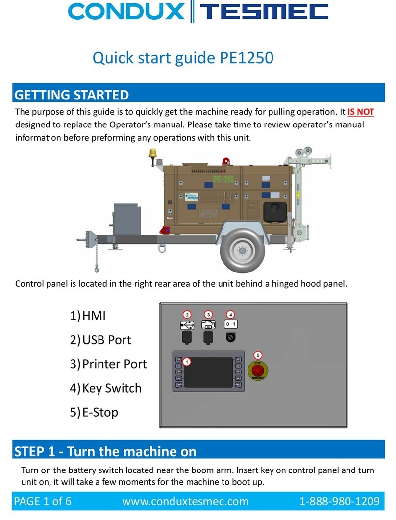
PT1150/PT1250/PT1252 Quick start guide
Tensioning operations
GETTING STARTED
The purpose of this guide is to quickly get the machine ready for pulling operation. It IS NOT designed to replace the
Operator’s manual. Please take time to review operator’s manual information before preforming any operations
with this unit.
Control panel is located in the left rear area of the unit behind a small access door.
Insert key and turn unit on, it will take a few moments for the machine to boot up.
PAGE 1 of 8 www.conduxtesmec.com 1-888-980-1209

Once the loading process is nished a check mark will appear in the lower right corner of the screen press the lower
right button to continue.
The next screen shown will only appear if scheduled maintenance is due.
If the screen above appears one of the maintenance timers has been tripped and the unit is due for scheduled mainte-
nance. This does not mean the unit needs to be removed from service, but it does need to be addressed by your
maintenance department at your earliest convenience. The screen can be cleared by pressing the lower right button.
This is the main operating screen, now that you are here you can start the engine by pressing the engine Start/Stop
Button. If operating in colder climates, the unit should be warmed up before use. Make sure the arrows matches the
ones in the RED boxes above, this indicates machine is being used as a tensioner. If you need to change it press the
button indicated in GREEN.
PAGE 2 of 8 www.conduxtesmec.com 1-888-980-1209

REEVING and ANCHORING
Reeving: For the working load of this machine under most circumstances 4 complete wraps are all that will be
needed. Additional wraps can be added if slipping problems occur. The units come with 135 feet of quality rated
rope when new to assist in loading bull wheels. Rope path is shown in RED in above images.
Anchoring: The GREEN lines drawn above show optimum anchoring angles to the ground. Proper anchoring
consists of anchors that will support 150% of the maximum working load required for the work being performed.
PAGE 3 of 8 www.conduxtesmec.com 1-888-980-1209

AUX EQUIPMENT MENU / SETTING JACK and STABILIZERS
With the machine correctly positioned and proper anchors established. You will want to deploy the stabilizer legs
and front hydraulic plow.
Press the button circled in RED above, this will bring you to the AUX equipment menu on the next page.
If the screen doesn’t appear to be the same as the one above, press the button highlighted in GREEN until it does.
The front plow can be operated by using the buttons highlighted in RED.
1. Lower front hydraulic plow, to take all weight o the trailer equipped transport jack. This jack needs to be fully
retracted, it was not designed to take the loads induced by pulling operations. This jack is for use in storage and
trailer connection purposes only.
2. Lower the tongue of the machine toward the ground. Final machine setup should be as close to level side to side
that can be achieved, and the machine level to tongue down angle.
3. With tongue lowered extend rear stabilizers.
4. Extend front plow to load rear stabilizer, the front plow is not designed to take the tires of the trailer completely
o the ground. It will relieve pressure before this occurs, It is normal.
5. Return to main screen by pressing the button marked above in ORANGE.
PAGE 4 of 8 www.conduxtesmec.com 1-888-980-1209

LINKING RADIO CONTROLLER AND FUNCTIONS
Now you are ready to acvate the radio control transmier, the indicator circled above indicates the radio is currently
not connected. To connect follow the steps below:
Turn on remote by rotang the switch shown above clockwise. Aer a few seconds the display will look similar to the
picture above. Verify you have a charged baery (lower le baery indicator) the green light in the upper right corner
will be blinking rapidly at this point. Make sure the joyscks is in the center posion and the E-Stop is released.
On the boom of the remote press and hold the green buon to link the remote to the machine. Once the remote is
linked the green indicator on the remote will blink less frequently and the yellow radio indicator on the control panel
screen will change from yellow to green.
PAGE 5 of 8 www.conduxtesmec.com 1-888-980-1209

REMOTE CONTROL, CONTROLLER SCREENS & SCREEN INDICATORS
Now the machine should be ready to operate, there are many more options and menus to access in the control panel.
Important information concerning safe operation and specications are listed in the Manual.
*** Sync switches mentioned above are for multiple machine operation. It is not covered in this quick start guide,
consult manual for more information.
PAGE 6 of 8 www.conduxtesmec.com 1-888-980-1209

AUX EQUIPMENT — REEL WINDER/REEL STAND
These ports at the rear of the unit are for connecting your reel winder/reel stand. Note that all Condux Tesmec reel winders
and reel stands operate between a pressure ranges of 450 psi to 2000 psi. Some important things must be done to avoid
dangerous or troublesome issues when using aux equipment.
1) Turn o the engine before trying to connect equipment to these ports. For less down time the Stop/Start Button can
be used to shut the engine o. Hold the button until engine stops and release, this will save time vs turning the key
o. If key is turned o the machine it will need to reboot and remote connection process reestablished.
2) Turn RW pressure settings down to zero and restart, the unit will only send pressure to the reel winder if the joystick
is moved out of the center position or is manually called on via the AUX equipment menu or the button on the
remote.
3) Refer to the Aux equipment information pertaining to your setup and follow how to prep for operation.
ROPE / CONDUCTOR CLAMP
The Rope/Conductor clamps main purpose is to hold the rope or conductor in the bull wheels while changing reels out
behind the machine, a secondary safety is also recommended.
The clamp can be operated from the switch on the remote control or via the AUX equipment menu.
There are a few things that are important to take note of when setting up the unit.
1) Rubber pad that holds rope or conductor is in good condition.
2) The clamp is positioned to clamp the last wrap on the bull wheel (reposition if needed).
3) Rope or conductor coming from the reel winder or reel stand and passing through the guide roller assembly on the
top of the unit.
PAGE 7 of 8 www.conduxtesmec.com 1-888-980-1209

ATTENTION:
This guide is designed to be used for quick reference and machine setup. Please take time to review the
complete manual for this machine before operating. The machine has many other options and menus not
covered by this guide.
You can download a manual pdf at any time for free by entering the machine serial number or trailer VIN number at:
https://conduxtesmec.com/manuals/
BASICS OF PULLING OPERATIONS
PAGE 8 of 8 www.conduxtesmec.com 1-888-980-1209
SETTING THE MAXIMUM PULL FORCE
Setting maximum pull force will limit the maximum allowable force the machine will apply to the pulling rope. When
set the unit will not pull with anymore force than programmed. If the machine reaches this level all motion will stop.
This knob on the controller is used to adjust the maximum pull force setting.
RECOVERING or PAYING OUT ROPE and/or CONDUCTOR
It is important not to make abrupt control inputs or direction changes. Slippage of the rope on the bull wheels may
occur, ease into the pull and gently increase speeds in either direction. When paying out rope, the rope will need to
have some tension on it to avoid slipping on the bull wheels. Damage will occur to the sectors if wire rope is allowed
to slip on the bull wheels.
NORMAL and LOW RANGE OPERATIONS
When using the unit as a puller described in this quick start guide there is no reason to use low range. If the display is
showing values less than the rated range of the machine it may be necessary to change settings REFER TO THE OPER-
ATORS MANUAL. NEVER CHANGE THE TRANSMISSION SETTING WITHOUT CLAMPING OFF THE CONDUCTOR
OR ROPE!!! Very dangerous conditions can occur if this process is handled incorrectly.
This manual suits for next models
2
Table of contents
Other Condux Industrial Equipment manuals

Condux
Condux 08097100 Instruction Manual

Condux
Condux CableGlider LW Instruction Manual

Condux
Condux 819 D.Drill Swivels User manual

Condux
Condux APS75 Instruction Manual

Condux
Condux Fiber Optic Cable Puller Trailer Instruction Manual

Condux
Condux TESMEC URW24 User manual

Condux
Condux TESMEC PE1250 User manual

Condux
Condux CableGlider Instruction Manual