manuals.online logo
Brands
  1. Home
  2. •
  3. Brands
  4. •
  5. Connoisseur Models
  6. •
  7. Toy
  8. •
  9. Connoisseur Models GWR HYDRA Diagram G19 User manual

Connoisseur Models GWR HYDRA Diagram G19 User manual

PROTOTYPE. The Great Western Railways designation HYDRA, covered a range
of low floored wagons designed to carry road vehicles such as horse drawn
carriages and motor cars and lorries.
They were designed with a gently sloping floor so that a vehicle could be driven
onto the wagon from an end loading dock and then sit within the well of the wagon.
This enabled tall road vehicles to remain within the loading gauge. They were brake
fitted and classified as ‘brown’ vehicles and were intended to be marshalled in
passenger trains.
The Hydra’s to diagram G19 were built in 1908 and ran into BR days. They carried
running numbers 42279-42288.
KIT. This is a very straightforward kit. Some push out rivet detail, a few parts
requiring simple folding and a selection of small detail parts make this an interesting
project.
Wheels are required to complete, 3’7”, Mansell Disc (Slater's Catalogue Number
7124). Available From Slater's Plastikard, Temple Rd, Matlock Bath, Matlock,
Derbyshire, DE4 3PG, Telephone 01629 583993.
Connoisseur Models, 33 Grampian Road, Penfields, Stourbridge,
DY8 4UE, Telephone 01384 371418
GWR HYDRA Diagram G19
Fitted Wagon for Carrying Road Vehicles
-0 Gauge -
GENERAL INSTRUCTIONS
Please read this section carefully, especially if this is your first etched brass kit. Many modellers
fight shy of working in this medium, but the basic skills are relatively easy to acquire. Once you’ve
learned how to form and solder brass, you’ll find all kinds of modelling possibilities will open up for
you.
Assembling an etched kit involves exactly the same skills that a scratchbuilder uses – the only
difference is that the cutting out of the parts is already done for you. Some filing and trimming will,
however, be necessary from time to time. Where this is the case, I have highlighted it in the
instructions.
The main skill to master is soldering and I would recommend a Weller 40 Watt soldering iron.
This has a 6mm diameter, removable copper bit. The bit is shaped like a screwdriver and has a
bright coating of solder (tinned). This combination of iron and bit shape is ideal for running fillet
joints and has a good reserve of heat, that is necessary for soldering small parts on to large
components. Note the shape and condition of a new bit, as this won’t last long and will need
restoring back to this condition.
It is important to keep the bit clean and in good condition as you work. Get a soldering iron stand
containing a damp sponge; old oxidized solder is wiped off on this before picking up fresh solder
for each joint. If you haven’t made a joint for some time you may find that a hard black crust has
formed on the bit. Remove this with a brass wire brush (suede brush) and then feed some
multicore solder onto each side of the bit to restore a bright surface (referred to as wetting or
tinning the bit). After about 8 hours use you will find the bit is in poor condition, with holes and a
ragged edge. File the bit back to its original shape using a hand bastard file and then polish the
surfaces on emery cloth. Coat the bit with Fluxite Soldering Paste (traditionally used by plumbers)
and this will prevent the bare copper oxidizing as the iron heats up. Then feed multicore solder
onto the bit to form a generous coating and leave to bubble away for a couple of minutes before
wiping excess off to give a bit almost as good as new.
A smaller Antex 25 Watt iron with a 3.2mm screwdriver bit is very useful for small assemblies and
detail work such as handrails, but will have insufficient heat reserve for main assembly work. The
Antex has a plated iron bit, after a little use with 145° solder a grey oxide appears on the bit that
will prevent you from picking up the solder. Touch the bit to some multicore solder and it will flash
over the bit, wetting it so that you can continue picking up 145° solder. I have found no problems
with mixing the two solders in this way.
I use 145° solder for virtually all assembly work. I prefer it in wire form but it is also produced in
stick form by Carrs. I find that its lower working temperature helps to give a quick clean joint.
Limiting the build up of heat in components, which may cause distortion. I find that I can hold parts
together with my finger ends and make a joint before heat reaches my fingers or other etched
parts drop off.
I use 60/40, tin/lead, fluxed multicore electrical solder (melting point about 190°) mainly to keep
the iron bits in good condition. As it gives a slightly stronger joint than 145° I sometimes use it for
small spot joints on handrail wire, lamp brackets etc, but still use extra liquid flux.
For all brass and nickel silver work I use Carrs green label liquid flux. You will soon get the feel
for how much to use but more problems are caused by too little flux than too much.
Before soldering components together, thoroughly clean both surfaces along the join line with a
glass fibre burnishing brush. Using your tweezers or a knife blade etc, hold the parts together in
the correct position and, with an old paintbrush, run some flux along the area to be joined. Still
keeping the parts correctly aligned, pick up a small quantity of solder on the tip of your iron and
carry it to the joint (unlike electrical soldering, when you feed solder into the joint). Hold the iron
against the joint just long enough for the solder to flash between the parts. Don’t let go of the parts
until the solder has cooled – this takes from five to ten seconds. To run a fillet of solder along a
joint, wait until the solder flashes between the parts and then pull the molten solder along
Page 2
the joint with the iron tip. Don’t load the iron tip with a lot of extra solder, but work the joint in 1”
lengths, bringing in small quantities of solder. Brass is a very forgiving material and if you get
something out of alignment, use heat from the iron to desolder the joint before starting again. For
complicated assemblies, it is a good idea to only tack solder parts together. You can then make
adjustments by desoldering until you are happy with the location of parts and then solder solid.
When you need to laminate two or more layers of brass together, align the parts and carefully
clamp them together, either in the vice or by holding them with miniature crocodile clips. Run flux
around the edges, and then go around with the soldering iron. Clean up thoroughly afterwards.
To fit small parts and overlays on to a larger assembly, such as strapping to a wagon side, when
you need to prevent finely detailed areas such as planking becoming clogged up with solder. Tin
the back of the small component first, then hold in place on the model and apply flux. Carefully
wipe the tip of your iron on a sponge to remove any solder from it (dry iron), and then touch it
against the parts to be joined. After a few seconds you’ll see molten solder bubbling from the
edges. Remove the iron, still holding the parts in place, and allow the joint to cool. An alternative is
to use solder paint (I would recommend Carrs 188 solder paste). As the name suggests, this is a
flux and solder in one. Simply apply a thin coat of solder paint to the back of the component
instead of tinning. Still apply a small amount of liquid flux before you solder the part into place.
Any surplus solder should be removed using a craft knife, I find No 10 curved scalpel blades
ideal, then burnish clean with a glass fibre brush. With practice, you’ll learn how to use the
minimum amount of solder to do the job. Flux is corrosive so, after each soldering session, give
your model a good scrub with washing up liquid or Jif. After a day or two, any remaining flux
residues will show as a green film, which should be washed away.
To cut parts from the fret, use a sharp Stanley knife on a piece of hardboard or a pointed scalpel
blade on a block of softwood. Remove tags and burrs with a fine file.
Three-dimensional parts are formed by folding. On an etched brass kit, the fold lines are normally
half-etched on the inside of the fold. You’ll be able to fold most parts using smooth-jawed pliers.
For longer parts folding bars are desirable.
Other useful tools include a bench vice, a good pair of tweezers, a set of Swiss files (get a full set
of cheap ones and then buy quality replacements for the three that you use the most), a pin vice
with a selection of drills from 0.5mm to 2.1mm plus a few larger sizes that you use regularly
(2.6mm for axle bearings etc), some square-nosed pliers and some very pointed-nosed ones,
preferably with smooth jaws. Buy cheap tools first and duplicate the most used ones with quality.
Try to complete all high-temperature soldering before attaching any of the cast whitemetal parts.
These can be attached with two-part epoxy resin such as Devcon or Araldite Rapid. Ensure the
surfaces to be glued are clean and free of grease.
Abetter alternative is to solder your white metal castings using Carrs 70 degree low melt solder
and Carrs red label white metal flux. The iron should be run at a much lower heat so that you do
not melt the castings. I have a domestic light dimmer switch and plug socket fixed to a piece of
wood, wired up with a lead and 3 amp mains plug to the input side of the dimmer switch and the
output of the dimmer switch into the plug socket (remember to continue the earth). Plug your 40
Watt iron (25 Watt iron won’t work) with a clean and freshly tinned bit into this and experiment with
adjusting the switch until you find the range of temperature at which the solder melts, but a scrap
casting does not. Note as the iron is running at a lower voltage it will take longer to heat up, so
when you think the adjustment is correct do check a few minutes later on another scrap casting to
see that it doesn't melt. Then scribe a mark on the switch knob to indicate this position.
When attaching white metal fittings to brass the surface of the brass must be tinned with 145°
solder, to allow the solder to grip. The surface of the casting at the joint should be burnished
bright. The casting can then be soldered into place with 70° solder and fillets of solder run into any
gaps with no risk of melting the casting.
Page 3
GWR HYDRA Diagram G19
The Hydra’s to diagram G19 were built in 1908 and ran into BR
days. They carried running numbers 42279-42288.
Livery, All over GWR passenger stock brown (Railmatch enamel
spray No 1602). Axle boxes and springs, brake gear and wheels,
buffer heads, black. Planked floor, dirty wood. White end to brake
lever. Lettering, yellow (ochre). Transfers for lettering are available
from, Historical Model Railway Society, Brian Webb (volunteer
sales officer), 8 Gilpin Green, Harpenden, Herts AL5 5NR.
Send SAE for list and order form or they are stocked by some
specialist retailers. These are Pressfix type and you will require
sheet 11 GWR goods vehicle insignia.
For BR period technically the brown paintwork should become bauxite
on fitted wagons but looking at photos (black & white) it looks as if in
reality the only livery change was to prefix the number with a W.
There is a nice selection of 1/43 scale diecast road vehicles available
that would make suitable loads and Andy Duncan, 34 Waters Road,
Salisbury, Wilts, SP1 3NX, Tel 01722 321041, produces a range of kits
for horse drawn vehicles.
For more information and photographs of the prototype wagon I would
recommend, GWR Goods Wagons, Atkins Beard & Tourret, Tourret
Publishing, ISBN 0-905878-07-8. Get it from your local library via their
book order system. The G19 Hydra is featured on pages 162-164.
Casting Identification and Parts Check List
1 X 6” length of 0.9mm brass wire (for brake cross shaft). 1 X 6” of spring steel Wire (for buffer springing, may be tarnished).
4 X Buffer
Heads/Shanks
4 X Buffer
Retaining
Collars
4 X Buffers
4 X Axle Boxes
2 X Screw
Coupling Centres
2 X Vacuum
Brake Pipes
When I made the centrifugal mould to produce a full set of castings for this wagon (one mould two spins) I took a bakers dozen
approach to the number of sub masters I placed in the mould. So you should find extra castings to guard against accidents &
mishaps but the quantities listed are the minimum required for the wagon.
Page 4
GWR Hydra
Main Assembly
Brakegear Assembly
Page 5
Page 6
GWR HYDRA Suggested Assembly Order
1. Solder together the two sections of floor, parts 1. The kit was originally designed to fit on to
spare brass on a loco kit and this is why it is in effect two sets of identical components. Place the
two floor halves face down (plank detail) on to a flat surface and push one side up against the edge
of a steel rule to ensure that they are aligned properly. Then solder the overlap joint, spot solder
each side first and then run a fillet of solder down the joint. If you are generous with the flux this
should help to pull the solder into the joint and underneath the overlap. Then offer each side of the
floor to the steel rule and if necessary dress off with a flat file any slight high spots so that each side
is completely straight.
Fold up the floor, use a side frame as a guide to form these folds at the correct angles. First fold
the bottom lip of the buffer beam 90°. I clamped the lip in my vice with the fold line just above the top
of the jaws and placing a steel rule at the back, pulled forward and down to form the fold. The rest of
the folds I made with the help of two square cornered blocks of softwood (off cuts of 2” X 1” etc).
2
5 16
3
9 6
12
7
1
15
10 13114 14
8
8
Screw Coupling
GWR HYDRA
Etched Parts
Identification
Place the floor face down on top of one block, with the buffer beam top fold line level with the edge
of the block. Place the second block on to the floor, again with its edge level with the fold line. Then
pressing down on to the wooden blocks with my thumbs, I pulled the buffer beam upwards with my
fingers to form a 90° fold. Any slight distortion can be corrected with gentle finger and thumb
pressure. The first fold for the well is made at the fifth plank joint from the ends. Again clamp the
floor between the wooden blocks. Then lay a steel rule with its edge level with the other side of the
plank line, on to the part of the floor that requires folding. Press down on the rule with your finger
ends to form the fold (use a side frame to determine the angle) the steel rule will help to transfer
your finger pressure evenly, to give a sharp fold at the plank line without rippling the adjacent
planks. The second fold for the bottom of the well is made in the same way but the fold line is on the
underside of the floor.
2. Fold over and solder the axle box keeper plates on the sideframes, parts 2. Emboss the eight
bolt heads on the rivet detail overlay, part 3, and then fit to the side frames. The bolt heads are
designed to be embossed using a scriber, with the point rounded off slightly on an oilstone. Place
the part face down onto a block of softwood and press firmly down into the half etched hole. This
may slightly distort the overlay, so once all the bolt heads are embossed, gently correct this by
bending back with finger and thumb pressure.
I soldered the rivet detail overlay to the side frame by holding it in place with miniature crocodile
clips (make sure that the slots are aligned and clear). Then using plenty of flux and placing the iron
bit flat on to the edge of the two parts I ran a fillet of solder along the edge. You should find that the
flux pulls the solder down between the two parts laminating them together, work about 1” at a time
and work along the bottom edge first and then the top edge. Then dress the two edges with a flat file
and clean off any solder on the front face of the side frame with knife blade and fibre brush. Then fit
the spring stops, parts 4, into the slots in the side frame.
Fit the side frames to the floor, there are etched dotted lines on the floor and etched grooves in the
buffer beams to help with their positioning. I found that I had to slightly dress the ends of the side
frames with a flat file to get a snug fit at the buffer beam bottom lip. Tack solder only, the side
frames to the floor of the well. Now fit the wheels, there should be enough flexibility in the side
frames to enable you to spring the wheel sets with bearings fitted on the axle ends into place. Check
that the side frames are square to the floor and then solder solid by running a good fillet of solder
along the inside edge. Try to run 1” fillets of solder at any one time, working from the centre towards
each buffer beam. Alternate between each side frame to prevent the build up of heat that may cause
distortion. Keep checking as you go to ensure that the side frames are still square to the floor. The
wheel sets will be flopping about between the side frames and we will sort this out later.
Page 7
3. Fit the curb rails, parts 5. Dress off the tags on the bottom edge but leave the top edge
attached to the smaller components and fix down to a block of softwood with drawing pins. Then
solder the floor into the half etched groove on the curb rail. Cut through the tags with a sharp,
pointed scalpel blade to release the curb rail. It is easier to solder the large formed up floor squarely
on to the fixed thin strip of curb rail rather than trying to solder a separate curb rail onto the edge of
the floor. Solder between the inside of the curb rail and the plank ends of the floor. Use plenty of flux
and a small amount of solder and hopefully the solder will run along the joint without clogging up the
plank detail. Again work the joint about 1” at a time, from the centre outwards, to avoid a build up of
heat. Repeat for the other curb rail.
Check by eye that the body is not twisted (twist square if it is). Centre each wheel set by pressing
the ends of the bearings onto the axle ends with finger and thumb and then quickly spot solder the
bearings into the side frames. If you have wenches fingers that are unable to withstand a little heat,
you may cut two squares of card from the material that the kit was packed on and use these
between your finger ends and the bearings to prevent burning yourself (I included some packing
washers but found it easier not to use them). Place the wagon onto a flat surface and check that it
sits on all four wheels without rocking. If not, you can adjust the height of any wheel by re-soldering
its bearing as you apply gentle pressure with the end of a flat file.
4. Fit the triangular bracing plates, parts 6. These are a bit fiddly but it is worth taking your time to
get them on clean and square. I fitted the four plates along the rivet detail overlay by holding them
with a miniature crocodile clip (the trick with small components is to attach a big handle to them, self
locking tweezers are also useful) and trying to keep the plate as square as possible pass the tab
through the slot in the side frame and spot solder at the back. You can then twist the plate slightly
with long-nosed pliers to get it exactly square before soldering solid to the underside of the floor.
Then applying plenty of flux, I touch the iron with a small amount of solder on the bit to the tab
previously spot soldered at the back of the side frame. The solder should flash around the tab and
be drawn through to the front face filling any gaps. You may have to dress the end of the bracing
plate with a flat file to get it to sit flat on the floor between curb rail and side frame and the tab and
notch to get it to fit flat against the rivet detail overlay. Have a dry run with each plate before
soldering into place.
The two bracing plates above the axles are a little trickier as you cannot get in to tack solder them
at the back. I found that I could hold them in place with a knifepoint and spot solder the tip to the
edge of the curb rail. I then fitted the rivet detail strips, parts 7. I tin the backs of these before
removing them from the fret, and then clean off the tags. Holding them in place with a knifepoint I
apply plenty of flux and then touch the edge with a dry iron until molten solder appears around all
the sides. Hopefully the solder has also flashed along the bracing plate soldering it solid to the side
frame. Then remake the bracing plate to floor joint. Clean off excess solder around all the bracing
plates with a knife blade and fibre brush. As you will see, the trick with small components is to tack
solder them into place first and then adjust them square with long-nosed pliers before soldering
solid.
5. Fit the end loading plates, parts 8, into the half etched rebates in the floor. I held them in place
with a knifepoint and applied plenty of flux and then soldered the back edge to the floor. The flux
should draw the solder down in to the etched rebate and slightly underneath the plate. I then
soldered the underside of the plate to the top of the buffer beam. Again using plenty of flux so that
the solder is drawn underneath the plate.
Fit the end loading plate supports, parts 9. These are designed to be folded up and fitted in to slots
in the buffer beam. The problem is that I have made the slots slightly too close together but if you
make the folds really tight they will just fit. Fold up as tight as you can and then holding the centre in
the jaws of a pair of long-nosed pliers place between your vice jaws. Slowly tighten the vice, the
pliers should prevent the top buckling and the triangular sides should be forced inwards closing up
the half etched fold lines. Straighten up the triangular sides and hopefully the support will now fit into
the slots. Solder the top to the loading plate and then if necessary, square up the triangular sides
with long-nosed pliers before soldering them to the buffer beam. Be generous with flux and solder
so that the slots are filled.
6. Fit coupling plates, parts 10, to the buffer beam. I tin the backs of the plates and then hold
them in place on the buffer beam with a knifepoint (narrow side to top, widest to bottom) ensuring
that the coupling slots are aligned. Using plenty of flux and only a little solder on the iron tip, I touch
the edge of the plate until molten solder appears around the edges.
Fold up the lamp brackets, parts 11. Then holding the top of the bracket with tweezers apply a
generous blob of flux and then touch the side of the lamp bracket with the tip of the soldering iron
coated with 60/40 electrical solder. The flux should draw the solder off the iron tip into the fold lines
to reinforce them. Then fit the lamp bracket to the buffer beam, locating its end into the slot.
7. Fit the brake lever brackets (V hangers) parts 12, behind the side frames and at one end only.
A little filing of the front leg of the ‘V’ will be necessary to allow it to fit slightly under the buffer beam
lip. There are etched grooves on the inside face of the side frame and these must still be clear after
fitting the bracket (brass rod and brake levers will be fitted later).
Page 8
Solder the brake blocks, parts 13, to the brake hangers, parts 14. Then fold the bottom of the brake
hanger 90°. Holding the brake block with a crocodile clip, position it so that it is just clear of the
wheel tread and solder the bottom of the hanger to the floor. There are etched grooves on the inside
face of the side frames that the bottom of the brake hanger will fit into. These will help to position the
bottom of the hangers correctly.
Make up the screw coupling (there is also a pair of simple hooks on the main fret if
you prefer these). Solder together both halves of each coupling hook. Using round-
nosed pliers form the four links in to ‘U’ shapes, dress the tops of two links so that
they will pivot freely in the hole in the coupling hook. Pass one of these links
through the hole in the coupling hook and then spring the ends over the pegs of the
cast coupling centre, then fit the second link. Pass the coupling hook shank through
the slot in the buffer beam and retain it with a length of spring wire that will also
spring the buffers. Polish the centre of this wire with emery cloth first so that you
can solder it to the coupling hook shank once you are happy that the buffers spring
freely. I find that I get the best joint onto spring wire using fluxite paste
and 60/40 electrical solder.
8. The buffers are a standard casting designed to be sprung and they work well on conventional
wagons. With the Hydra having deep, close together side frames, there is very little clearance and
the buffers are better fitted as solid. File a flat on to one side of the backs of the buffer bodies (to
form a D shape) so that they will fit centrally in the D shaped buffer beam holes. Then drill out
2.1mm the buffer bodies to take the cast head/shank. I hold the drill bit in a pin vice (chuck) and grip
the buffer body between finger and thumb. Use a little spot of spit on the end of the drill (some more
technical people have a block of furniture polisher’s beeswax that they smear on the drill end). This
will help to prevent the drill wandering in the white metal and breaking through the side of the buffer.
Drill through the body from each end so that the hole breaks through in the middle. Pass shank
through body and low melt solder together at the back. Tin the buffer beams with 145° solder and fit
the buffers using low melt solder. You will only be able to solder at the bottom so polish bright the
back of the buffer body and use plenty of flux to help the solder flow underneath.
This said it is possible to make the buffers
sprung. Prepare the bodies as before, then snip
off some of the narrow end of the shank to leave
just over 1mm from the step and after passing
the shank through the body, low melt solder a
retaining collar on to the shank. Make sure that
this is a good joint and that the solder flows all
around the collar. File a flat on to the collar (you
will need to file down to the shank at the brake
lever end) so that it will clear the side frame.
Offer the buffer in to place to check that it will depress without jamming on the side
frame. When you are happy with clearances solder the buffers into the buffer beam.
Retaining collar
Solder
Spring steel wire
Buffer Assembly & Springing
9. Fit the brake yokes, parts 15, by springing between the brake
blocks and spot soldering with 60/40 solder at each end. Pass a length
of 0.9mm brass rod through the holes in the brake lever brackets, Solder
into place and then cut each end so that they project 2mm from each bracket. Using long-nosed
pliers, fold up the brake levers, parts 16. Folding the ends around to form a handle with the circular
shield behind. Solder the levers to the projecting ends of the brass rod.
10. Fit the cast axle boxes/springs to the side frames, locating over the bearings. I soldered them
into place with low melt but they could also be glued on with araldite. Fit the cast vacuum pipe to the
buffer beam just to the left of the coupling hook. This casting is a very difficult shape to mould and
the master buried itself in the mould. To release it and subsequent castings I had to make heavy
knife cuts so that the mould would flex to release the casting. This tends to cause some casting
flash that will require cutting and filing away. That should now be the metalwork construction
completed.
Form up and
File Top Link
To Swing
Freely
Cast
Centre
Page 9
11. Painting is a vast subject that cannot be covered fully here. The important thing with a metal
model is to get a good base coat of primer. Hopefully you have been cleaning up and washing the
model at the end of each modelling session, but it will still need thoroughly cleaning before painting.
I give my models a good scrub with a stiff-bristled paint brush in a sink full of hot (as hot as your
hands can bear) water and cheap washing up liquid (the expensive stuff that’s kind to your hands
has an oil in it that will stop the paint keying to the metal). If you know somebody who works in
catering and can scrounge you some industrial-strength liquid, this is better still. Then rinse the
model a couple of times in clean warm water and place in a dust-free box to dry.
I use car aerosol primer and Halfords grey primer is one of the best. For the best results you want
to spray at room temperature (25°C) on a dry (avoid cold, damp or humid) day. I find it helps to
warm the model to about 30°C (put it in the airing cupboard overnight) and I warm up the paint tin by
putting it onto a radiator (about 40°C, but use your common sense as I don’t want anybody blowing
themselves up). I find it best to prime the model in two light coats, about 15 minutes apart and then
leave for 48 hours to harden off (in the airing cupboard in a dust-free box).
I brush-paint my models with Humbrol enamel. For years I just stirred it up and painted straight
from the tin but I was never completely happy with the results. Recently two things have transformed
my painting. The first was a copy of Martyn Welch’s book, The Art of Weathering, Wild Swan
Publications, ISBN 1 874103 11 9. His basic techniques are very useful and almost foolproof.
Martyn’s method of creating worn and weathered planking for wagon floors by blending brown and
grey paints to form a base. Then dry brushing darker shades to represent the wood grain, is
particularly effective on this type of wagon. The second thing is to mix the paint in the tin and then
transfer it to a palette (a sheet of clean plasticard) with blobs of lighter and darker shades of paint
surrounding the main colour. Then work the paint with the brush on the palette, slightly varying the
tones of the paint. This seems to totally change the texture of the paint and the way it goes on and
covers on the model.
I hope that you have found these instructions and description of my building techniques helpful.
Hopefully they have pointed you in the right direction but please remember that no two people build
a model in exactly the same way. The key is to experiment as you build more models and develop a
set of techniques that suit you. I am always happy to help with advice particularly when I am at a
show with my sales stand.
Can You Help Me?
If you have enjoyed building this kit and have been satisfied with the quality, I would be most
grateful if you could recommend it to your friends and fellow modellers. Although my kits are not
perfect, I try to put a lot of time and effort into producing them. If I can get extra sales of a kit through
customer’s personal recommendation and I find that word of mouth is the best form of advertising.
This will help me to put extra time and money into developing the next kit. Hopefully this will give me
more satisfied customer to recommend my kits to their friends.
If you are not happy with this kit then please tell me. Hopefully I will then be able to help and sort
out any problem.
Page 10
Page 11

Other Connoisseur Models Toy manuals

Connoisseur Models LNER Class G5 0-4-4 Tank User manual

Connoisseur Models

Connoisseur Models LNER Class G5 0-4-4 Tank User manual

Connoisseur Models train User manual

Connoisseur Models

Connoisseur Models train User manual

Connoisseur Models Six Wheeled All Third Coach User manual

Connoisseur Models

Connoisseur Models Six Wheeled All Third Coach User manual

Connoisseur Models LNER Class Y7 User manual

Connoisseur Models

Connoisseur Models LNER Class Y7 User manual

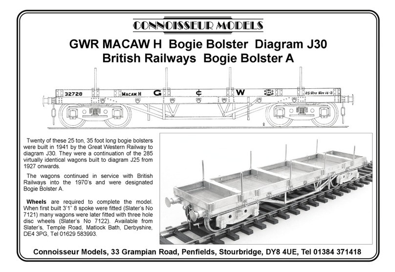
Connoisseur Models GWR MACAW H User manual

Connoisseur Models

Connoisseur Models GWR MACAW H User manual

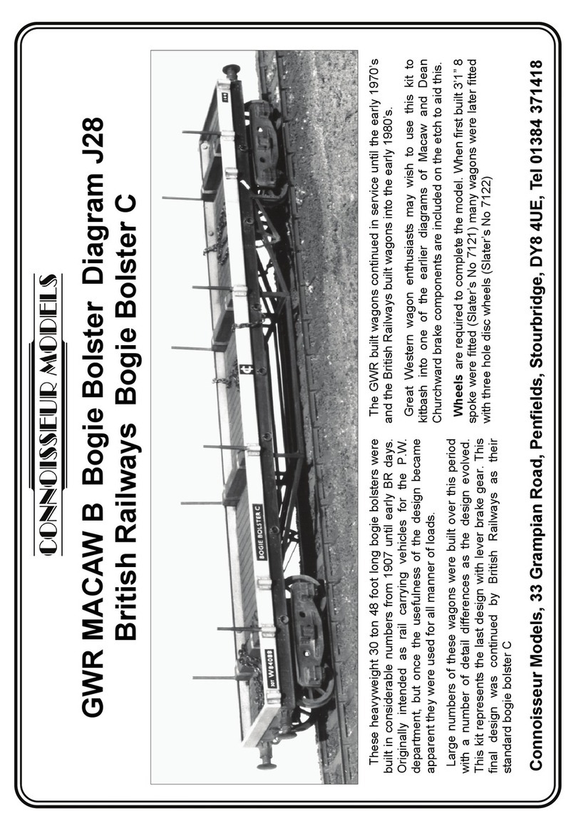
Connoisseur Models GWR MACAW B Bogie Bolster Diagram J28British Railways Bogie Bolster... User manual

Connoisseur Models

Connoisseur Models GWR MACAW B Bogie Bolster Diagram J28British Railways Bogie Bolster... User manual

Connoisseur Models GWR Loriot M User manual

Connoisseur Models

Connoisseur Models GWR Loriot M User manual

Connoisseur Models LNER Toad E User manual

Connoisseur Models

Connoisseur Models LNER Toad E User manual

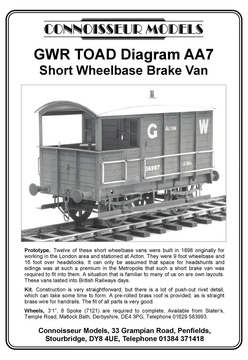
Connoisseur Models GWR TOAD Diagram AA7 User manual

Connoisseur Models

Connoisseur Models GWR TOAD Diagram AA7 User manual

Popular Toy manuals by other brands

Fisher-Price Imaginext H5341 instruction sheet

Fisher-Price

Fisher-Price Imaginext H5341 instruction sheet

marklin 26545 instruction manual

marklin

marklin 26545 instruction manual

Black Horse Model PIPER CUB NC 76510 Instruction manual book

Black Horse Model

Black Horse Model PIPER CUB NC 76510 Instruction manual book

marklin 78070 user manual

marklin

marklin 78070 user manual

VTech Baby Baby Beats Monkey Drum user manual

VTech Baby

VTech Baby Baby Beats Monkey Drum user manual

Bengtson Company Mister Mulligan instructions

Bengtson Company

Bengtson Company Mister Mulligan instructions

Fisher-Price Power Wheels CBG61 owner's manual

Fisher-Price

Fisher-Price Power Wheels CBG61 owner's manual

Mattel M8490 instructions

Mattel

Mattel M8490 instructions

LEGO Education 45816 Assembly instructions

LEGO

LEGO Education 45816 Assembly instructions

Eduard M1133 MEV Assembly and quick start guide

Eduard

Eduard M1133 MEV Assembly and quick start guide

REVELL '68 DODGE CHARGER R/T 3'N 1 user guide

REVELL

REVELL '68 DODGE CHARGER R/T 3'N 1 user guide

ROBBE BLUE ARROW XL 490 operating instructions

ROBBE

ROBBE BLUE ARROW XL 490 operating instructions

Fleischmann 9475 Operating	 instruction

Fleischmann

Fleischmann 9475 Operating instruction

Eduard MiG-21F-13 accessories quick start guide

Eduard

Eduard MiG-21F-13 accessories quick start guide

Frenchman River Model Works 86 manual

Frenchman River Model Works

Frenchman River Model Works 86 manual

Alien Aircraft Corp P-51D Mustang Assembly instructions

Alien Aircraft Corp

Alien Aircraft Corp P-51D Mustang Assembly instructions

Hornby R3060 CLASS A1 TORNADO Operating and maintenance instructions

Hornby

Hornby R3060 CLASS A1 TORNADO Operating and maintenance instructions

REVELL HMMWV M1025 Armament Carrier & M998 Cargo/Troop... Assembly manual

REVELL

REVELL HMMWV M1025 Armament Carrier & M998 Cargo/Troop... Assembly manual

manuals.online logo
manuals.online logoBrands
  • About & Mission
  • Contact us
  • Privacy Policy
  • Terms and Conditions

Copyright 2025 Manuals.Online. All Rights Reserved.