Connoisseur Models LNER Class G5 0-4-4 Tank User manual

Connoisseur Models, 1 Newton Cottages, Nr Weobley,
Herefordshire, HR4 8QX, Telephone 01544 318263
0 Gauge Locomotive Kit
LNER Class G5 0-4-4 Tank
Prototype. This class of 110 locomotives was built from 1894. They were the
standard design of passenger tank until 1907. In later years members of the class
wandered southwards. They worked on outer London suburban services and
East Anglia branch lines. The class lasted until 1958.
Kit. The body is etched in brass with nickel silver being used for the chassis. The
bogie is sprung and compensated. Slide bars and valve gear are represented
between the frames. Cab interior is detailed and a cast back head is provided.
Alternative components for bunker, buffer beams and other later changes made
to some locomotives are provided. Etched fire irons and a choice of number
plates are included.
This kit has been designed to provide a set of quality components, that will allow
the modeller who has basic kit building skills to build an 0 gauge model of the
prototype, to a standard of detail that is suitable for operating models on most 0
gauge layouts.
Parts Required To Complete
2 Sets 3’1”, 12 Spoke Bogie Wheels (Slater’s Catalogue Number 7837NE)
2 Sets 5’11/2”, 16 Spoke Driving Wheels (Slater’s Catalogue Numbers 7861)
Plunger Pickups if desired (Slater’s Catalogue Number 7157)
Handrail Knobs if desired as a replacement for split pins (Slater’s Catalogue
Numbers, Long-7951, Short-7952)
Available From Slater’s Plastikard, Old Road, Darley Dale, Matlock
Derbyshire, DE4 2ER, Telephone 01629 734053.
Mashima 1833 Motor and 40/1 Gear Set.

GENERAL INSTRUCTIONS
Please read this section carefully especially if this is your first etched brass kit. Many modellers
fight shy of working in this medium but the basic skills are relatively easy to acquire. Once you’ve
learned how to form and solder brass you’ll find all kinds of modelling possibilities will open up for
you.
Assembling an etched kit involves exactly the same skills that a scratchbuilder uses – the only
difference is that the cutting out of the parts is already done for you. Some filing and trimming will be
necessary from time to time. Where this is the case I have highlighted it in the instructions.
The main skill to master is soldering and I would recommend a Weller 40 Watt soldering iron. This
has a 6mm diameter removable copper bit. The bit is shaped like a screwdriver and has a bright
coating of solder (tinned). This combination of iron and bit shape is ideal for running fillet joints and
has a good reserve of heat that is so necessary for soldering small parts onto large components.
Note the shape and condition of a new bit as this won’t last long and will need restoring back to this
condition.
It is important to keep the bit clean and in good condition as you work. Get a soldering iron stand
containing a damp sponge as old oxidized solder is wiped off on this before picking up fresh solder
for each joint. If you haven’t made a joint for some time you may find that a hard black crust has
formed on the bit. Remove this with a brass wire brush (suede brush) and then feed some multicore
solder onto each side of the bit to restore a bright surface (referred to as wetting or tinning the bit).
After about 8 hours use you will find the bit is in poor condition with holes and a ragged edge. File
the bit back to its original shape using a hand bastard file and then polish the surfaces on emery
cloth. Coat the bit with Fluxite Soldering Paste (traditionally used by plumbers) and this will prevent
the bare copper oxidizing as the iron heats up. Then feed multicore solder onto the bit to form a
generous coating and leave to bubble away for a couple of minutes before wiping the excess off to
give a bit almost as good as new.
A smaller Antex 25 Watt iron with a 3.2mm screwdriver bit is very useful for small assemblies and
detail work such as handrails, but will have insufficient heat reserve for main assembly work. The
Antex has a plated iron bit and after a little use with 145° solder a grey oxide appears on the bit that
will prevent you from picking up the solder. Touch the bit to some multicore solder and it will flash
over the bit wetting it so that you can continue picking up 145° solder. I have found no problems with
mixing the two solders in this way.
I use 145° solder for virtually all assembly work. I prefer it in wire form, available from many tool
merchants, but it is also produced in stick form by Carrs. I find that its lower working
temperature helps to give a quick clean joint and limits the build up of heat which may cause
distortion in components. I find that I can hold parts together with my finger ends and make a joint
before heat reaches my fingers or other etched parts drop off.
I use 60/40 tin/lead fluxed multicore electrical solder (melting point about 190°) mainly to keep the
iron bits in good condition. As it gives a slightly stronger joint than 145° I sometimes use it for small
spot joints on handrail wire, lamp brackets etc, but still use extra liquid flux.
For all brass and nickel silver work I use Carrs green label liquid flux. You will soon get the feel for
how much to use but more problems are caused by too little flux than too much.
Before soldering components together thoroughly clean both surfaces along the join line with a
glass fibre burnishing brush. Using your tweezers or a knife blade etc, hold the parts together in the
correct position and with an old paintbrush run some flux along the area to be joined. Still keeping
the parts correctly aligned, pick up a small quantity of solder on the tip of your iron and carry it to the
joint (unlike electrical soldering when you feed solder into the joint). Hold the iron against the joint
just long enough for the solder to flash between the parts. Don’t let go of the parts until the solder
has cooled – this takes from five to ten seconds. To run a fillet of solder along a joint, wait until the
solder flashes between the parts and then pull the molten solder along the joint with the iron tip.
Don’t load the iron tip with a lot of extra solder work the joint in 1” lengths bringing in small quantities
of solder.
Page 2

Brass is a very forgiving material and if you get something out of alignment use heat from the iron
to desolder the joint before starting again. For complicated assemblies it is a good idea to only tack
solder parts together. You can then make adjustments by desoldering until you are happy with the
location of parts and then solder solid.
When you need to laminate two or more layers of brass together align the parts then carefully
clamp them together either in the vice or by holding them with miniature crocodile clips. Run flux
around the edges and then go around with the soldering iron. Clean up thoroughly afterwards.
To fit small parts and overlays on to a larger assembly, such as strapping to a wagon side, when
you need to prevent finely detailed areas such as planking becoming clogged up with solder tin the
back of the small component first, then hold in place on the model and apply flux. Carefully wipe the
tip of your iron on a sponge to remove any solder from it (dry iron), and then touch it against the
parts to be joined. After a few seconds you’ll see molten solder bubbling from the edges. Still
holding the parts in place remove the iron and allow the joint to cool. An alternative is to use solder
paint (I would recommend Carrs 188 solder paste). As the name suggests this is a flux and solder in
one. Simply apply a thin coat of solder paint to the back of the component instead of tinning. Still
apply a small amount of liquid flux before you solder the part into place.
Any surplus solder should be removed using a craft knife, I find No 10 curved scalpel blades ideal,
then burnish clean with a glass fibre brush. With practice you’ll learn how to use the minimum
amount of solder to do the job. Flux is corrosive so after each soldering session give your model a
good scrub with washing up liquid or Jif. After a day or two any remaining flux residues will show as
a green film which should be washed away.
To cut parts from the fret use a sharp Stanley knife on a piece of hardboard or a pointed scalpel
blade on a block of softwood. Remove tags and burrs with a fine file.
Three-dimensional parts are formed by folding. On an etched brass kit the fold lines are
normally half-etched on the inside of the fold. You’ll be able to fold most parts using smooth-jawed
pliers. For longer parts folding bars are desirable.
Other useful tools include a bench vice, a good pair of tweezers, a set of Swiss files (get a full set
of cheap ones and then buy quality replacements for the three that you use the most), a pin vice
with a selection of drills from 0.5mm to 2.1mm plus a few larger sizes that you use regularly (2.6mm
for axle bearings etc), some square-nosed pliers and some very pointed-nosed ones, preferably with
smooth jaws. Buy cheap tools first and duplicate the most used ones with quality.
Try to complete all high-temperature soldering before attaching any of the cast whitemetal parts.
These can be attached with two-part epoxy resin such as Araldite Rapid. Ensure the surfaces to be
glued are clean and free of grease.
A better alternative is to solder your white metal castings using Carrs 70 degree low melt solder
and Carrs red label white metal flux. The iron should be run at a much lower heat so that you do not
melt the castings. I have a domestic light dimmer switch and plug socket fixed to a piece of wood,
wired up with a lead and standard mains plug fused at 3 amps to the input side of the dimmer switch
and the output of the dimmer switch into the plug socket (remember to continue the earth). Plug
your 40 Watt iron (25 Watt iron won’t work) with a clean and freshly tinned bit into this and
experiment with adjusting the switch until you find the range of temperature at which the solder
melts but a scrap casting does not. Note as the iron is running at a lower voltage it will take longer
to heat up, so when you think the adjustment is correct do check a few minutes later on another
scrap casting to see that it doesn't melt. Then scribe a mark on the switch knob to indicate this
position.
When attaching white metal fittings to brass the surface of the brass must be tinned with 145°
solder to allow the solder to grip. The surface of the casting at the joint should be burnished bright.
The casting can then be soldered into place with 70° solder and fillets of solder run into any gaps
with no risk of melting the casting. Virtually all castings will be improved by a little extra fettling work.
Flash can be cleaned out using a sharp pointed knife blade, part lines removed by scraping back
with a curved blade and then blending in using a fibreglass brush. The casting moulds tend to distort
when metal flows in so check castings for square and even thickness.
Page 3

SPECIFIC INSTRUCTIONS FOR LOCOMOTIVE KITS
Hole Sizes. Because of the etching process holes will normally be found undersize, for example the
turned brass bearings will not fit holes in chassis sides, and a simple fitting operation is required.
The best tool for opening up holes of this size is a cheap tapered reamer available at most model
railway shows from tool suppliers. By rotating this gently in the hole you quickly open holes to
correct size, without risk of
tearing the metal. By trial and
error on the first hole you will
soon establish how much
material requires removal. For
smaller holes, such as those for
the location of casting's etc
these are best opened up using
a set of cheap tapered
broaches, or by twisting a small
round file in the hole.
Forming Parts. While the boiler
in this kit is pre-formed, other
forming is best achieved as construction progresses as this enables the parts to be adjusted to each
other. To make a tight curve at full metal thickness, such as tank front, bunker rear etc, take a piece
of rod slightly under size of the curve required (a drill shank is ideal). Place roughly on centre line of
bend, holding in place with thumbs and pull upwards with fingers, forming approximately 30 degrees
of the bend. Check with eye and adjust if necessary before forming 60 degree of bend then offer
part to model. Final adjustment of fit is easily made on last stage of bending.
To form shallow curves, splasher tops, smoke box wrappers etc, use a piece of pipe or broom
handle. Diameter is not crucial, a piece of one-inch water pipe covers cab roof to smoke box
wrapper. Place part over tube and hold in place with finger and thumb of one hand. Work the metal
in stages over tube with finger and thumb of the other hand until correct radius is formed.
A technique you may find useful in working metal is to soften and remove the spring from the metal
by heating (called annealing). The part is held with pliers and heated in a gas flame. (The gas
cooker is ideal). Alternatively use a pencil torch that runs off lighter fuel. Heat part until a purple
band appears close to the edges and then remove from heat. Do not overheat part as it will then
become too soft and unworkable. Remember you can reheat if not workable. Allow part to cool
naturally in the air.
Damaged Parts and Shortages. If you damage an etching during construction it is not possible to
replace individual pieces, but I am quite flexible in providing at minimum cost replacement frets (this
will contain all the brass or N/S parts). Where a casting is damaged individual items can be replaced
as I have full control of production. Because of the complexity of the product, combined with the low
volume way it is produced, I try to exercise a high degree of quality control in production and
packing but if you find you are short of an item or find a sub standard part please approach me for a
replacement.
Fibreglass Scratch Brush. The scratch brush is like a propelling pencil holder into which a
fibreglass refill is fitted and which will give a vigorous abrasive action. I find this tool indispensable
for cleaning up and removing solder. One very useful tip is to soak the refills in dilute PVA glue
(Evostick resin W wood glue let down 50/50 with water and a spot of washing up liquid) and then
drill holes in a block of wood and stick the ends of the refills in the holes while they harden off. This
will make the refills much more abrasive and longer lasting and also stops the fibres breaking off
and ending up in your fingers. You will need to give the refill a good rub to get it started but if you
use green label flux you will soon have plenty of rusty tools that need cleaning.
A fibreglass brush and most other general modelling tools can be obtained from Squires Model and
Craft Tools, 100 London Rd, Bognor Regis, West Sussex, PO21 1DD, Tel 01243 842424. They do a
free catalogue and a very good mail order service.
TR0005 Micro Drill Reamer 1mm-5mm
BRC250 6 Piece Cutting Broach Set 0.7-2mm
BRC300 12 Piece Cutting Broach Set 0.65-4mm
TR0010 Tapered
Reamer 3mm-12mm
Three very useful tools purchased from SQUIRES,
100 London Road, Bognor Regis, West Sussex,
PO21 1DD, Telephone 01243 842424.
Page 4
Page 5
LNER 0-4-4 Tank Class G5 Parts Identification
Backhead X 1
Backhead Spacer
X 1
Chimney X 1
Dome X 1
Safety Valve
Cover X 1
Smokebox Door
X 1
Bufferbeam X 2
LNER Buffers
X 4
NE Buffers
X 4
Air Reservoir
Tank X 1
Sandboxes
X 2
Airbrake
Cylinder X 1
Springs X 4
Coupling
Centres X 2
Safety Valves
X 2
2 No Whistles
Large & Small
Brake Handle
X 1
Smokebox
Door Handle
X 1
Valve Cover X 1
Water Filler
Cap X 2
Westinghouse
Pump X 1
Front Air Pipe
X 1
Front Sandbox
Filler X 2
Rear Air Pipe
X 1
Smokebox
Door Wheel
X 1
Smokebox
Blower Valve
X 1
Steam Heat
Pipe X 2
Twin Pipe Oil
Box X 2
Vacuum Pipe
X 2
Regulator and hand
wheel etch X 1
Track pins X 2
Selection of Wire and Rod
1.8mm dia Copper Rod X 6”
1.6mm dia Brass Rod X 3”
1.2mm dia Copper Rod X 6”
1.4mm dia Copper Rod X 12”
0.7mm dia Brass Wire 10” long X 4
0.9mm dia Brass Wire 10” long X 4
0.45mm dia Spring Brass Wire 10” long
(for use as wire wiper pickups) X 2
1” small bore copper tube
20swg tinned copper wire 3 turns
22swg tinned copper wire 3 turns
Sundry Parts
Printed Circuit Board Strips For Use with
Wire Wiper Pickups
Turned Brass Axle Bearings X 8
6BA Screws X 3
6BA Brass Nuts X 5
6BA Brass Washers X 2
8BA Brass Screws X 2
8BA Brass Nuts X 2
Split Pins for Handrail Supports X 12
Electrical Wire for Pickups.
1 X 18” Black 1X 18” Red

Page 6
Drawing shows NER
Class O & early LNER
Class G5.
The kit has been
designed to build a loco
in this condition.
Drawings are only
approximately to scale.
Drawing by Colin Foster

Page 7
A - Regulator Pipe (paint red)
B - Vacuum Pipe (paint black)
C - Steam Heating Pipe
D - Anti Vacuum Valve
E - Vacuum Controlled Regulator
F - Vacuum Cylinder
G - Electric Bell Connectors
The drawing does not depict a particular loco but
shows detail changes made to the class in later
days. Note that individual locos would not have all
the modifications. Alternative parts are not
provided in the kit to cover all modifications.
Drawings are only approximately
to scale
LNER and BR Class G5 0-4-4T
Drawing by Colin Foster

Page 8

Page 9

Page 10
The first section of the instructions show full
chassis construction, but in practice you
can build a basic chassis and then use this
to check body clearance. Then complete
the assembly of the two parts together.
Parts are numbered in a logical assembly
order. Tack solder a part in place, then
adjust the next part to match. Some parts
are designed oversize to be trimmed to
size. Solder solid when happy.
Main Chassis Construction
Fit top wire
across
chassis
first, then
thread brake hanger
and block over this. Solder in
place just clear of wheel. Then fit
bottom wire and pull rods.
Brake
Hangers

Page 11
Inside Valve Gear
To build compensated bogie. Fit one sideframe to part 7, locking in
place with screw. Make sure side frame is parallel with top and bottom
of part 7, then tack solder to part 7.
Fit second sideframe, locking in place with screw, then back of the
screw 1/4 turn. Solder screwhead into hole in part 10. The sideframe
should then pivot on the screw thread. When happy with the running of
the loco, file screwheads flush with part 10.
Spring
Cross section of bogie mounting
Adjust spring tension by
running nut up or down screw.
Use two nuts to lock each
other onto screw
Tube, 5mm
long
0.9mm wire
Solder 8BA nut
over hole
Fit front
bearings from
inside
Fit rear bearings from outside or fit from
inside and file pivot hole into a slot
Solder parts 9 & 10 together. Then
open hole out to clear 8BA screw head.
Then solder to part 8.
Bogie
Construction

Page 12
Brake Linkage
Cast brake cylinder
Brass rod
Top view
Sandpipes from
0.9mm wire Fit etched balance weights and chassis castings
A suggestion for making
Wire wiper pick ups
Bend wire into loop
and fill with solder
solder
Leads to
motor
After painting the chassis fit electrical pickups
and motor/gears and set up for sweet running.
I have included parts for making a wire wiper
pickup system and pilot holes that can be
opened up for Slater’s plunger pickups are
included on the side frames.
With these instructions I have assumed that
you are experienced in setting up a chassis. If
this is not the case extra instructions are
included on the instruction sheet that comes
with my motor and gearset. These can be
downloaded free of charge from my website
www.jimmcgeown.com or send a SAE and I will
be pleased to provide them.
I have also produced comprehensive hints and
tips help sheets for using Slater’s wheels,
plunger pickups, etc. These can also be
downloaded free of charge from my website
www.jimmcgeown.com or send a SAE and I will
be pleased to provide a free copy of my hints and
tips booklet for new customers.

Page 13
Main Body Construction
Alternative Part
Fit cast buffer beam instead of rivet detail
overlay on later locos.
Reinforce with solder
Fold out tabs for boiler

Page 14
Fit spectacle rings and coal bars
made from 0.45mm wire before
main construction
Alternative Cab Back and Bunker
Cut out to clear windows
0.9mm brass wire
Trim back at joint
Cab Beading
You may find it desirable
to fit beading before main
construction
0.7mm brass wire
Spot solder to footplate

Page 15
You may find it desirable to
fit parts 45 & 46 before
main construction
Cab Interior
Cab Roof
Rainstrip
from soft wire
Brass rod

Page 16
Front Splasher
Cut off excess and file flush
with underside of footplate.
Smokebox
Firmly fix with drawing pins the smokebox front to a block of
wood and roughly pre-form the smokebox wrapper using an
off cut of pipe and drill shanks etc. Position the wrapper to the
centre of the smokebox front top (note etched centre
marks). Starting from the top work your way round,
soldering to the front and using this as a former. Solder
spacers in place, then solder smokebox rear to
wrapper.
Alternative Part
Some later locos had a second riveted
smokebox wrapper. Line up with chimney
hole on part 62 and solder around smokebox
Boiler and Smokebox
Make boiler and smokebox as a separate assembly.
Use smokebox to help with the construction and
positioning of front splashers. Then fit boiler
between tanks and fit smokebox into slots
on footplate. Line up and check all is
square, then tack solder boiler to
smokebox. Then remove from
between tanks and solder
joint solid. Fit joint
ring, then solder
into main
assembly.
Boiler and Smokebox
Make smokebox joint ring
from wire or 1mm square brass
with a radius filed onto one corner
Boiler. Pre-curve the boiler, pin a former to a block of wood
and solder boiler end to this. Repeat for other end then
finger and thumb boiler bottom circular and solder

Page 17
Cosmetic Screw Coupling.
Solder together both halves
of each hook and then using
round-nosed pliers form the
four links into U shapes.
Dress the tops of two links
with a file so that they will
pivot freely in the slot in the
hooks. Thread one of these
links through the hook and
spring the ends
over the pegs on
the cast centre.
Then fit the
bottom link.
I pass the hook shank through the buffer
beam slot then solder solid and trim off flush.
Form up and file
Top Link
To Swing
Freely
Cast
Centre
Pinch
Solder
Ply or Card
Fit the handrails made from 0.7mm brass wire. In
common with the other kits in my range I have
included split pins to support the handrails. These are
fairly easy to use and their appearance can give a
better representation of the prototype handrail
supports than some of the turned brass alternatives.
Fire Tool Brackets
Cab Steps
Front Steps

Page 18
Casting Positions
To fit castings use main drawings for reference. Later locos had the Westinghouse Pump
fitted onto the front of the left hand tank. Early locos had it in a cupboard in the cab. Some
alternative castings are provided to help you build later locos.
Note: 2nd handrail knob
and end of handrail on
C/L of dome
Fire tool brackets
2 No. whistles
Westinghouse
air pump
Fire tool brackets
(tank filler omitted
for clarity)
Note alternative boiler fittings and positions.
Hole centres are marked on underside of boiler.

Page 19
To get the loco to run steady, you will have to put weight forward of the second driving axle.
I used a piece of 1” copper water pipe full of molten lead in the front of the boiler. I secured
this with milliput. You will find a bit of experimentation with weight and bogie spring tension
will be necessary to get the best running on your layout.
Prototype Reference
This kit was developed from an article by Colin Foster in the North Eastern Express No 119,
the journal of the North Eastern Railway Association. Colin Foster kindly gave me
permission to use his drawings for the instructions.
As the G5 class had numerous detail changes made throughout their lives a good
photograph of you chosen prototype is essential. Try to get one of the two following books.
An Illustrated History of N.E.R. Locomotives.
Ken Hoole
Oxford Publishing Co.
Locomotives of the LNER, Part 7
The Railway Correspondence and Travel Society
Etched Safety Valve Levers solder two
together
Etched Tank Filler Handles
Remove regulator from etch and
bend to form handles at ends
Table of contents
Other Connoisseur Models Toy manuals

Connoisseur Models
Connoisseur Models Six Wheeled All Third Coach User manual

Connoisseur Models
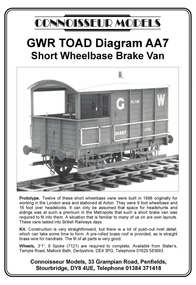
Connoisseur Models GWR TOAD Diagram AA7 User manual

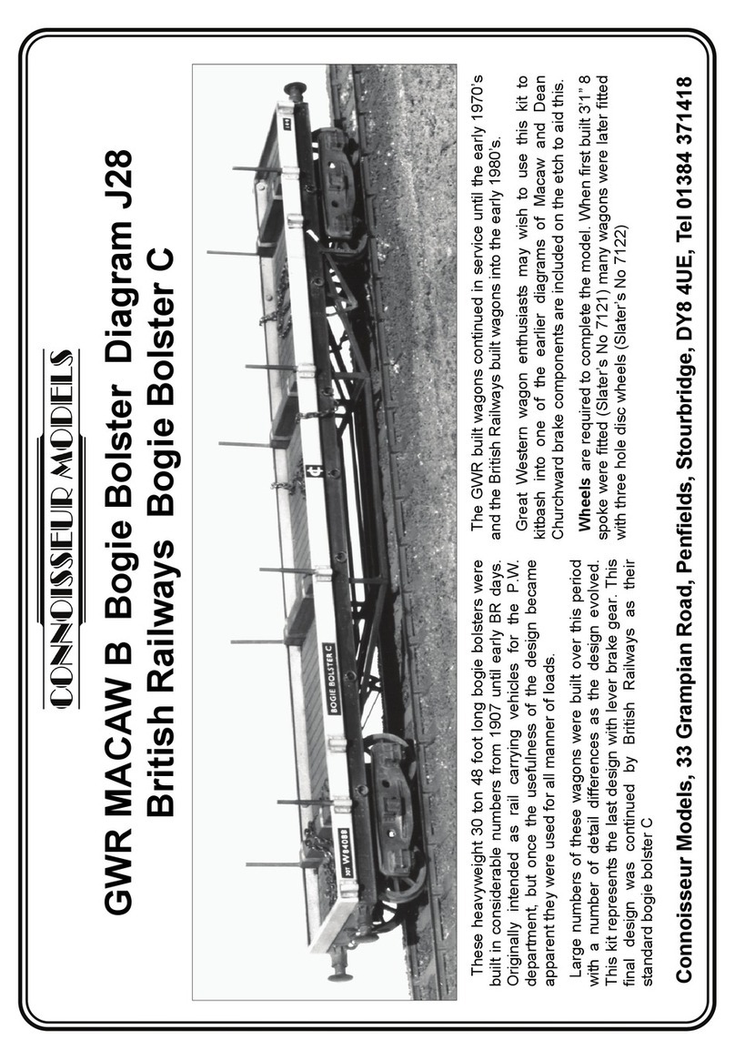
Connoisseur Models
Connoisseur Models GWR MACAW B Bogie Bolster Diagram J28British Railways Bogie Bolster... User manual

Connoisseur Models
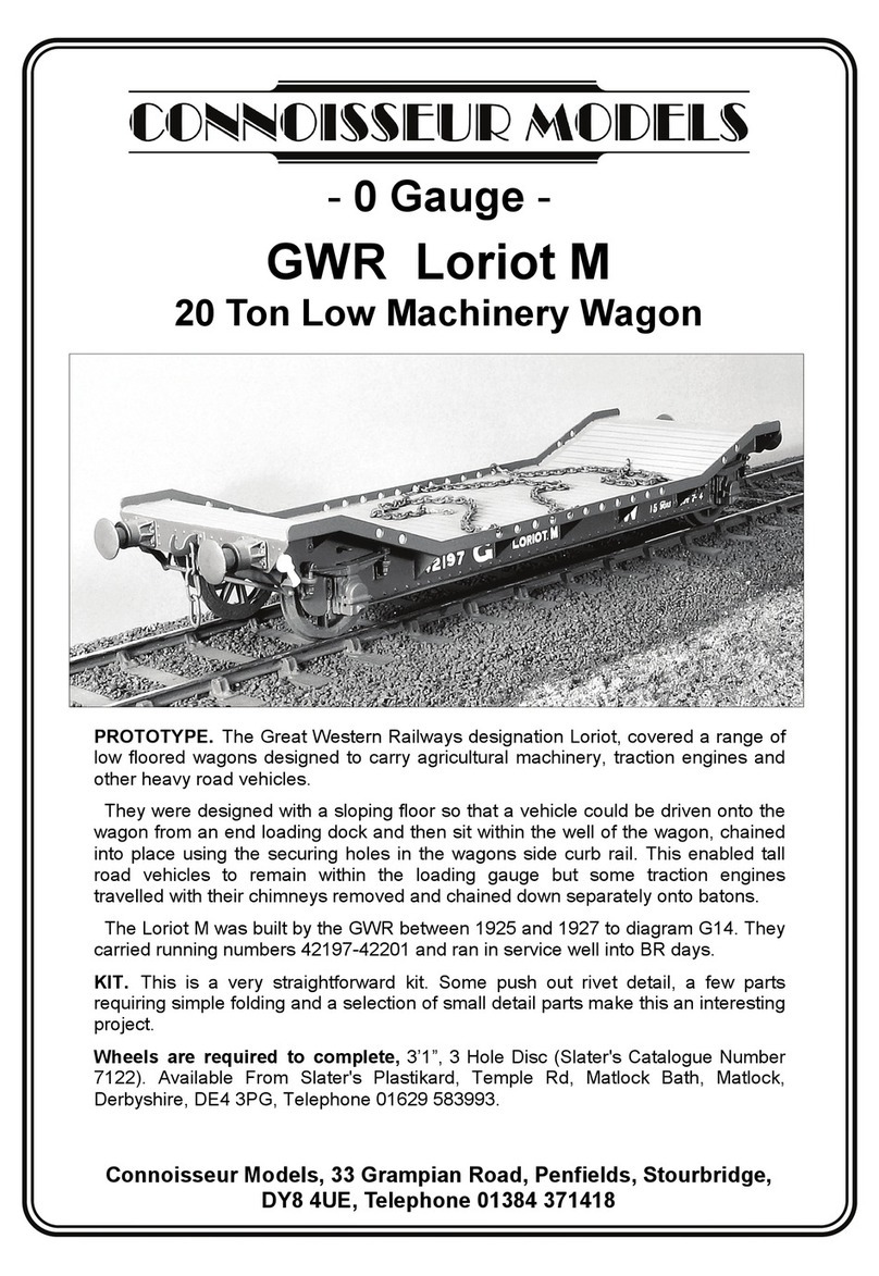
Connoisseur Models GWR Loriot M User manual

Connoisseur Models
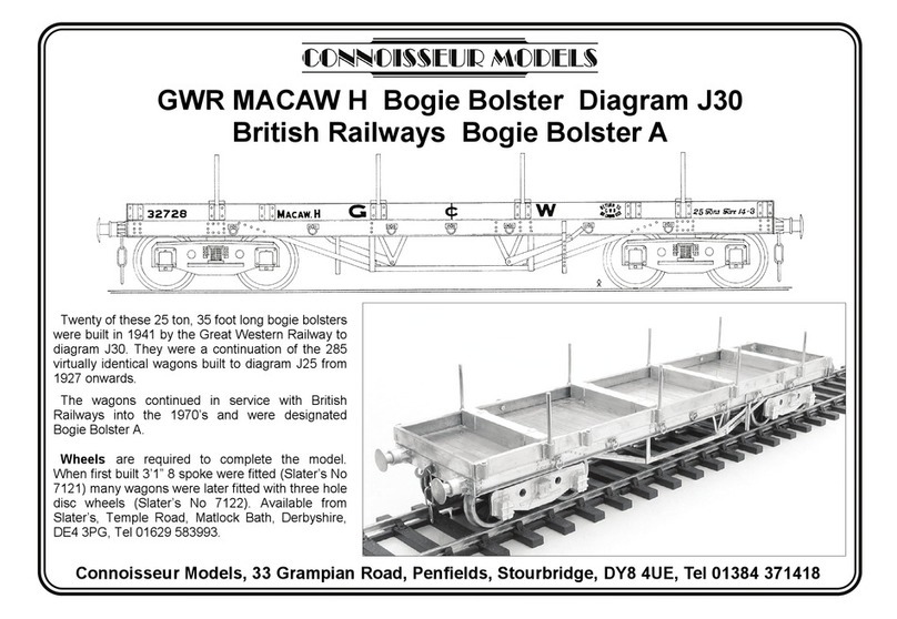
Connoisseur Models GWR MACAW H User manual

Connoisseur Models
Connoisseur Models LNER Class Y7 User manual

Connoisseur Models
Connoisseur Models train User manual

Connoisseur Models
Connoisseur Models LNER Toad E User manual

Connoisseur Models
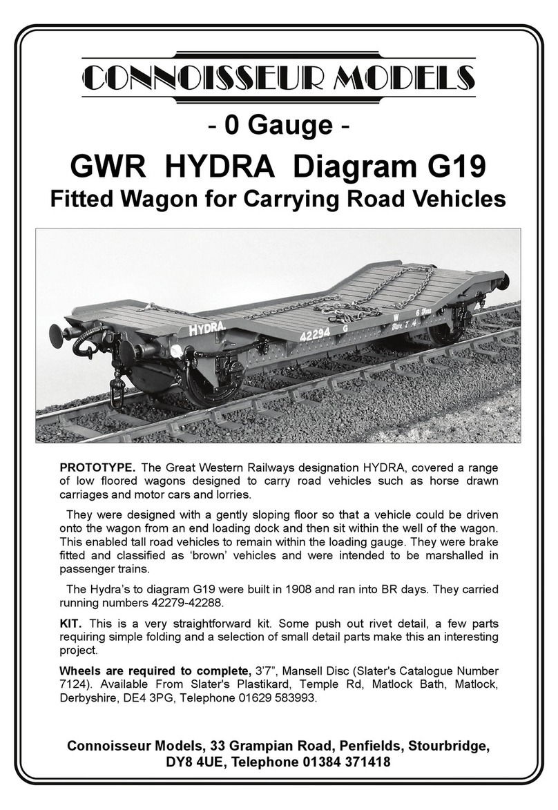
Connoisseur Models GWR HYDRA Diagram G19 User manual