LMS 4F CHASSIS ASSEMBLY
9. Take the main frames (parts 48) and using a tapered
reamer open out the axle holes so that the turned brass
bearings will be a snug fit. If you are fitting plunger pickups
then also open out the holes for these so that the housing will
be a snug fit.
Take the frame spacers (parts 49) and where appropriate
fold them through 90°. The rear spacer is slightly tight on the
axle gear wheel and so you may wish to fold this one through
95° to give a little extra clearance.
Now pin one side frame down to a flat block of wood with
the top of the frame slightly overhanging the edge of the
block. Solder each spacer firmly into place. Fit second
sideframe checking with an enginers square that the two
sideframes are exactly opposite each other. Tack solder the
second frame at the tabs only and start in the centre and
work to each end. Remove the chassis from the wood block
and check that it is square and not twisted. Once you are
happy solder all joints solid.
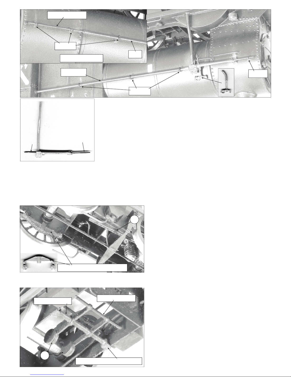
Fold the reversing gear weight shaft brackets that project
upwards from the top edge of the frames into inverted U
shapes and reinforce the folds with a spot of solder.
Laminate together the the reversing gear balance weights
(parts 50) and fold over the circular ends to form four metal
thicknesses. Cut a length of 1.5mm brass rod to a length that
will be a spring fit between the frame brackets and thread the
weights onto this and solder centrally 6mm apart. Fit a length
of 0.9mm brass wire through the holes in the ends of the
weights and trim down to slightly less than chassis width and
then solder the 1.5mm brass rod weight shaft solidly to the
chassis brackets.
50
Fold over to form shaft brackets
0.9mm brass wire 1.5mm brass rod
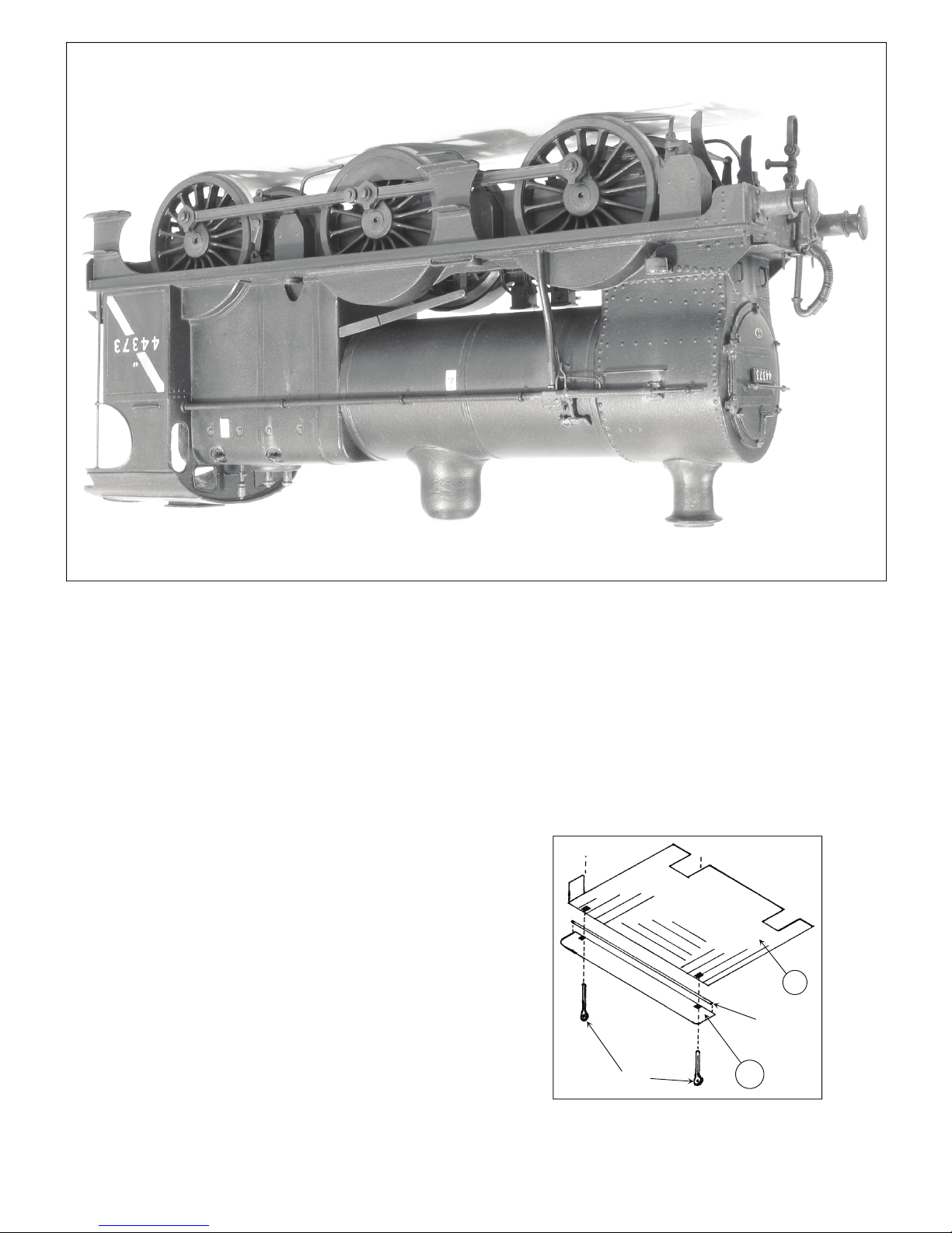
Fold up the ash pan sides (parts 51) and solder into the half
etched rebates on the inside of the frames
51
Note how cast spring fits to frame
PAGE 10
time spent working on the top surface with knife blade and
fibre brush removing part lines and casting blemishes will be
well rewarded. Any casting porosity marks can be filled with
70° solder and polished back smooth. Check that you are
happy with the way the roof fits and file or scrape the
underside edges if required. Solder the roof into place with
70° solder fitting two lengths of (tinned with 145°) soft wire at
the joints between roof and cab side. Using plenty of flux
allow a generous amount of 70° solder to flow over the wire
and around the joints. Then scrape back with knife blade and
clean up with fibre brush to reveal the wire rainstrips and
blend the cab roof into the sides with no sign of a joint. Drill
out hole in centre of cab roof and fit the roof ventilator.
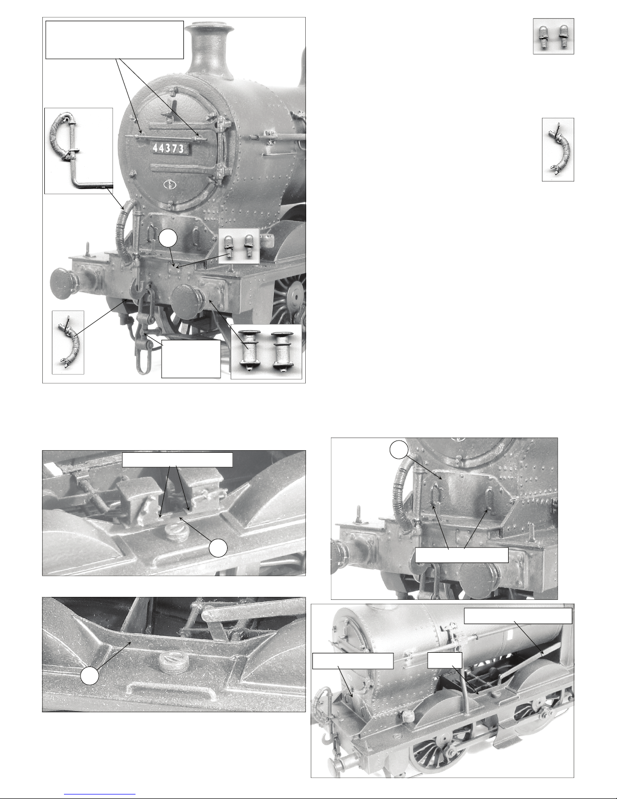
16. On the prototype loco the boiler handrails were
actually pipes the R/H one feeding the smoke box blower the
L/H one feeding the vacuum ejector.
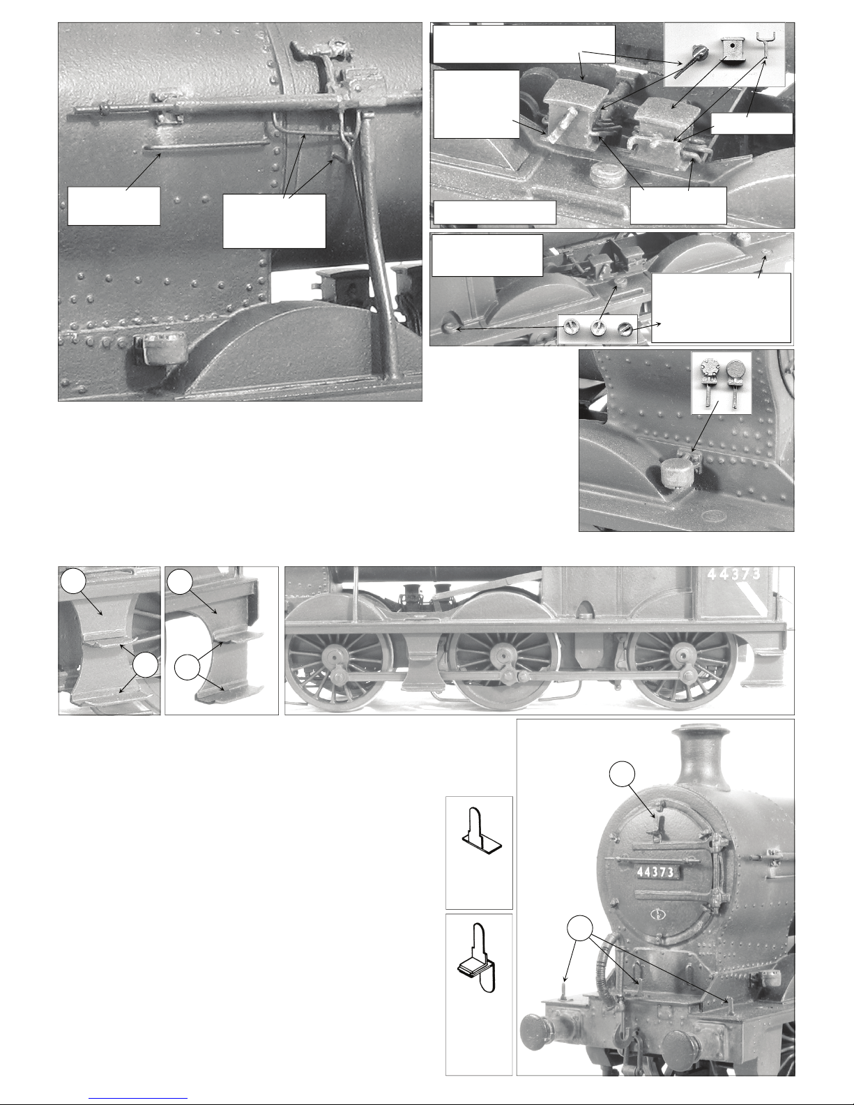
On the model these are represented with brass tube cut to
length and opened out split pins threaded on. The split pins
are gently squeezed closed at the back so that they form
tightly around the tube and then mounted into the boiler. A
length of 0.7mm brass
wire is fitted into the
tube to continue the R/
H handrail along the
smoke box. The cast
vacuum ejector has
0.7mm brass wire cast
into it and this is fitted
into the L/H tube to
again continue it along
the smoke box.
Fit
into
tube
Continue along
smoke box
Right Hand handrail
Tube
Split pins
0.7mm Brass wire
Brass tube
Split pins
Split pin
PAGE 19