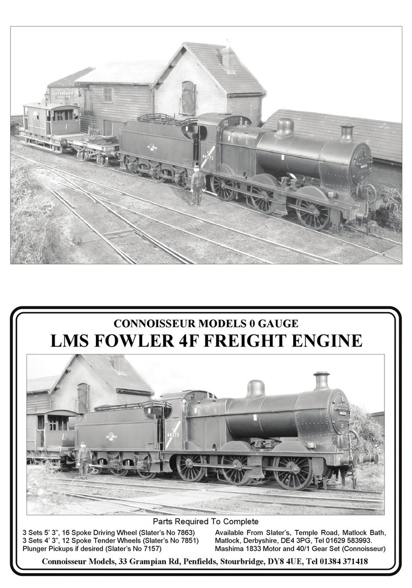
Connoisseur Models LNER Class Y7 User manual

Page 36
LNER Class Y7
Kit Composition. The main body and chassis components are etched in
brass with cast white metal fittings. Cab interior is detailed and a cast
backhead is provided. Alternative castings are included to cover some of the
modifications and differences between members of this class of loco that
existed during their working lives. The etched brass boiler is pre-rolled and
wire, screws, bearings etc are included.
This kit has been designed to provide a set of quality components that will
allow the modeller, who has basic kit building skills, to build an 0 gauge
model of the prototype to a standard of detail that is suitable for operating
models on most 0 gauge layouts.
Parts Required to Complete
2 Sets 3’6”, 10 Spoke Driving Wheels (Slater’s Cat No 7842W),
Plunger Pickups if desired (Slater’s Cat No 7157),
Available from Slater’s, Old Road, Darley Dale, Matlock,
Derbyshire, DE4 2ER, Tel 01629 734053.
Mashima 1833 Motor and 40/1 Gear Set (available from myself).
Connoisseur Models, 1 Newton Cottages, Nr Weobley,
Herefordshire, HR4 8QX, Telephone 01544 318263

GENERAL INSTRUCTIONS
Please read this section carefully especially if this is your first etched brass kit.
Many modellers fight shy of working in this medium but the basic skills are
relatively easy to acquire. Once you’ve learned how to form and solder brass you’ll
find all kinds of modelling possibilities will open up for you.
Assembling an etched kit involves exactly the same skills that a scratchbuilder
uses – the only difference is that the cutting out of the parts is already done for
you. Some filing and trimming will be necessary from time to time. Where this is the
case I have highlighted it in the instructions.
The main skill to master is soldering and I would recommend a Weller 40 Watt
soldering iron. This has a 6mm diameter removable copper bit. The bit is shaped
like a screwdriver and has a bright coating of solder (tinned). This combination of
iron and bit shape is ideal for running fillet joints and has a good reserve of heat
that is so necessary for soldering small parts onto large components. Note the
shape and condition of a new bit as this won’t last long and will need restoring back
to this condition.
It is important to keep the bit clean and in good condition as you work. Get a
soldering iron stand containing a damp sponge as old oxidized solder is wiped off
on this before picking up fresh solder for each joint. If you haven’t made a joint for
some time you may find that a hard black crust has formed on the bit. Remove this
with a brass wire brush (suede brush) and then feed some multicore solder onto
each side of the bit to restore a bright surface (referred to as wetting or tinning the
bit). After about 8 hours use you will find the bit is in poor condition with holes and
a ragged edge. File the bit back to its original shape using a hand bastard file and
then polish the surfaces on emery cloth. Coat the bit with Fluxite Soldering Paste
(traditionally used by plumbers) and this will prevent the bare copper oxidizing as
the iron heats up. Then feed multicore solder onto the bit to form a generous
coating and leave to bubble away for a couple of minutes before wiping the excess
off to give a bit almost as good as new.
A smaller Antex 25 Watt iron with a 3.2mm screwdriver bit is very useful for small
assemblies and detail work such as handrails, but will have insufficient heat
reserve for main assembly work. The Antex has a plated iron bit and after a little
use with 145° solder a grey oxide appears on the bit that will prevent you from
picking up the solder. Touch the bit to some multicore solder and it will flash over
the bit wetting it so that you can continue picking up 145° solder. I have found no
problems with mixing the two solders in this way.
I use 145° solder for virtually all assembly work. I prefer it in wire form, available
from many tool merchants, but it is also produced in stick form by Carrs. I find that
its lower working temperature helps to give a quick clean joint and limits the build
up of heat which may cause distortion in components. I find that I can hold parts
together with my finger tips and make a joint before heat reaches my fingers or
other etched parts drop off.
I use 60/40 tin/lead fluxed multicore electrical solder (melting point about 190°)
mainly to keep the iron bits in good condition, as it gives a slightly stronger joint
Page 2 Page 35

HMRS transfers, sheet number 18 contains NER loco & coach insignia. Details
and an order form can be obtained from HMRS Transfers, Brian Webb (volunteer
sales officer), 8 Gilpin Green, Harpenden, Herts, AL5 5NR.
After grouping the LNER continued the overall black lined red livery until around
1928 when they changed to unlined black. Lettering and number was on the side
tanks (see photo of LNER model). The LNER did not renumber most ex North
Eastern locos until 1946. HMRS transfers, sheet number 4A contains LNER yellow
insignia for black locomotives.
After painting you may wish to glaze the spectacle windows and a hole template is
located in the left hand corner of the fret. If you hold a sewing needle in a pin chuck
and use the template to scribe circles on the glazing material. You can cut these
out and these should pop perfectly into the inner spectacle rings (parts 9). For this
glazing you can use thin clear plasticard, but I prefer to cut flat sheets from the
clear blister packs that many items are packaged in nowadays. This has a textured
surface probably caused by the moulding process, which gives it a slightly opaque
quality that I think represents dirty windows just right.
I have included a oil bottle, bucket and loco crew and once painted these should
finish off the cab of your model nicely and hopefully your loco is now ready for a
long working life.
Reference Books
Locomotives of the LNER, Part 9B, Tank Engines-Classes Q1 to Z5.
The Railway Correspondence and Travel Society, ISBN 0 901115 41 X.
An Illustrated History of NER Locomotives, Ken Hoole,
Oxford Publishing Co, ISBN 0 86093 323 7.
North Eastern Record, Volume 3, J.M. Fleming, for the NE Railway Association,
published by The North Eastern Railway Association, ISBN 0 902 835 20 3.
Weblink, www.lner.imfo/locos/Y/y7shtml.
Page 34
than 145°. I sometimes use it for small spot joints on handrail wire, lamp brackets
etc, but still use extra liquid flux.
For all brass and nickel silver work I use Carrs green label liquid flux. You will
soon get the feel for how much to use but more problems are caused by too little
flux than too much.
Before soldering components together thoroughly clean both surfaces along the
join line with a glass fibre burnishing brush. Using your tweezers or a knife blade
etc, hold the parts together in the correct position and with an old paintbrush run
some flux along the area to be joined. Still keeping the parts correctly aligned, pick
up a small quantity of solder on the tip of your iron and carry it to the joint (unlike
electrical soldering when you feed solder into the joint). Hold the iron against the
joint just long enough for the solder to flash between the parts. Don’t let go of the
parts until the solder has cooled – this takes from five to ten seconds. To run a fillet
of solder along a joint, wait until the solder flashes between the parts and then pull
the molten solder along the joint with the iron tip. Don’t load the iron tip with a lot of
extra solder, work the joint in 1” lengths bringing in small quantities of solder.
Brass is a very forgiving material and if you get something out of alignment use
heat from the iron to desolder the joint before starting again. For complicated
assemblies it is a good idea to only tack solder parts together. You can then make
adjustments by desoldering until you are happy with the location of parts and then
solder solid.
When you need to laminate two or more layers of brass together align the parts
then carefully clamp them together either in the vice or by holding them with
miniature crocodile clips. Run flux around the edges and then go around with the
soldering iron. Clean up thoroughly afterwards.
To fit small parts and overlays onto a larger assembly, such as strapping to a
wagon side, when you need to prevent finely detailed areas such as planking
becoming clogged up with solder tin the back of the small component first, then
hold in place on the model and apply flux. Carefully wipe the tip of your iron on a
sponge to remove any solder from it (dry iron), and then touch it against the parts
to be joined. After a few seconds you’ll see molten solder bubbling from the edges.
Still holding the parts in place remove the iron and allow the joint to cool. An
alternative is to use solder paint (I would recommend Carrs 188 solder paste). As
the name suggests this is a flux and solder in one. Simply apply a thin coat of
solder paint to the back of the component instead of tinning. Still apply a small
amount of liquid flux before you solder the part into place.
Any surplus solder should be removed using a craft knife, I find No 10 curved
scalpel blades ideal, then burnish clean with a glass fibre brush. With practice
you’ll learn how to use the minimum amount of solder to do the job. Flux is
corrosive so after each soldering session give your model a good scrub with
washing up liquid or Jif. After a day or two any remaining flux residues will show
as a green film which should be washed away.
To cut parts from the fret use a sharp Stanley knife on a piece of hardboard or a
pointed scalpel blade on a block of softwood. Remove tags and burrs with a fine
file. Page 3

Three-dimensional parts are formed by folding. On an etched brass kit the fold
lines are normally half-etched on the inside of the fold. You’ll be able to fold most
parts using smooth-jawed pliers. For longer parts folding bars are desirable.
Other useful tools include a bench vice, a good pair of tweezers, a set of Swiss
files (get a full set of cheap ones and then buy quality replacements for the three
that you use the most), a pin vice with a selection of drills from 0.5mm to 2.1mm
plus a few larger sizes that you use regularly (2.6mm for axle bearings etc), some
square-nosed pliers and some very pointed-nosed ones, preferably with smooth
jaws. Buy cheap tools first and duplicate the most used ones with quality.
Try to complete all high-temperature soldering before attaching any of the cast
whitemetal parts. These can be attached with two-part epoxy resin such as Araldite
Rapid. Ensure the surfaces to be glued are clean and free of grease.
A better alternative is to solder your white metal castings using Carrs 70 degree
low melt solder and Carrs red label white metal flux. The iron should be run at a
much lower heat so that you do not melt the castings. I have a domestic light
dimmer switch and plug socket fixed to a piece of wood, wired up with a lead and
standard mains plug fused at 3 amps to the input side of the dimmer switch and the
output of the dimmer switch into the plug socket (remember to continue the earth).
Plug your 40 Watt iron (25 Watt iron won’t work) with a clean and freshly tinned bit
into this and experiment with adjusting the switch until you find the range of
temperature at which the solder melts but a scrap casting does not. Note as the
iron is running at a lower voltage it will take longer to heat up, so when you think
the adjustment is correct do check a few minutes later on another scrap casting to
see that it doesn't melt. Then scribe a mark on the switch knob to indicate this
position.
When attaching white metal fittings to brass the surface of the brass must be
tinned with 145° solder to allow the solder to grip. The surface of the casting at the
joint should be burnished bright. The casting can then be soldered into place with
70° solder and fillets of solder run into any gaps with no risk of melting the casting.
Virtually all castings will be improved by a little extra fettling work. Flash can be
cleaned out using a sharp pointed knife blade, part lines removed by scraping back
with a curved blade and then blending in using a fibreglass brush. The casting
moulds tend to distort when metal flows in so check castings for square and even
thickness.
SPECIFIC INSTRUCTIONS FOR LOCOMOTIVE KITS
Hole Sizes. Because of the etching process holes will normally be found
undersize, for example the turned brass bearings will not fit holes in chassis sides,
and a simple fitting operation is required. The best tool for opening up holes of this
size is a cheap tapered reamer available at most model railway shows from tool
suppliers. By rotating this gently in the hole you quickly open holes to correct size
without risk of tearing the metal. By trial and error on the first hole you will soon
establish how much material requires removal. For smaller holes, such as those for
the location of casting's etc, are best opened up using a set of cheap tapered
broaches, or by twisting a small round file in the hole.
Page 4
22. Painting is a vast subject that cannot be coveredfully here. The important thing
with a metal model is to get a good base coat of primer. Hopefully you have been
cleaning up and washing the model at the end of each modelling session but it will
still need thoroughly cleaning before painting. I give my models a good scrub with a
stiff-bristled paint brush in a sink full of hot water, as hot as your hands can bear,
and cheap washing up liquid (the expensive stuff that’s kind to your hands has an
oil in it that will stop the paint keying to the metal). If you know somebody who
works in catering and can scrounge you some industrial-strength liquid this is better
still. Then rinse the model a couple of times in clean warm water and place in a
dust-free box to dry.
I use car aerosol primer and Halfords grey primer is one of the best. For the best
results you want to spray at room temperature (25°C) on a dry day, avoid cold,
damp or humid days. I find it helps to warm the model to about 30°C (put it in the
airing cupboard overnight) and I warm up the paint tin by putting it onto a radiator
(about 40°C, but use your common sense as I don’t want anybody blowing
themselves up). I find it best to prime the model in two light coats, about 15 minutes
apart and then leave for 48 hours to harden off (in the airing cupboard in a dust-free
box).
I brush-paint my models with Humbrol enamel. For years I just stirred it up and
painted straight from the tin but I was never completely happy with the results.
Recently two things have transformed my painting. The first was a copy of Martyn
Welch’s book, The Art of Weathering, Wild Swan Publications, ISBN 1 874103 11
9. Martyn’s basic techniques are very useful and almost foolproof. The second
thing is to mix the paint in the tin and then transfer it to a palette (a sheet of clean
plasticard) with blobs of lighter and darker shades of paint surrounding the main
colour. Then work the paint with the brush on the palette, slightly varying the tones
of the paint. This seems to totally change the texture of the paint and the way it
goes on and covers on the model.
There is much debate about what are the precise livery details for any historical
loco at any time so I have assumed that if you are an established NER modeller
you will have your own reference library. If you are a general modeller who wants
general guidance then I don't think we can do better than look at how the preserved
locos are painted today and copy them. Try a google images search, “LNER Class
Y7”, then look for images on flicker, you will find plenty of colour pictures.
The standard NER livery for tank locos until 1904 was black for top surfaces of
footplate, steps, tank tops etc & smokebox. Boiler, tank sides, cab etc, Saxony
green with black edges lined white. Tank sides, ends and bunkers were panelled by
a 2” black band with a 3/16“ white line on each side. Buffer beams vermilion with
buffers and beams edged black and lined white. Cab roof colour is a bit unsure but
was probably grey when first painted but was very soon dirty black. Cab interior
cream with dirty wood floor.
From 1904 the NER changed tank loco livery to overall black with fine red lining
and lettered NER but locos would only be repainted when they entered works for
general repair.
Page 33
Fit lubricators, hopefully you have already decided the type you wish
to fit and have drilled the required location holes as you removed the
parts from the main fret. Locos were originally fitted with a ball type
lubricator mounted on either side of the smokebox.
These were later replaced on many locos with two pipe box type
lubricators. If your eyesight is good enough you may wish to represent
the fine oil pipes so before fitting to the tank fronts drill out the pipe union nuts to
give a slight rebate into which the pipe work fabricated from 24swg soft wire can be
located. I then fold a length of wire into two, trim the ends level and solder into the
pipe union nuts. Then form the two parallel pipes to run down and then behind the
bottom of the tanks. I find this easier than trying to fit two separate pipes.
Locos from the first builds were originally fitted with a
Ramsbottom safety valve. The separate safety valve lever should
be fitted to the safety valve body and then the end of the lever
trimmed back so that it will just touch the front of the cab.
The five post 1923 built locos were fitted with Ross
Pop valves mounted on a base. Some changes
happened to individual locos during the life of the
class caused by boiler swaps etc, so check your
photos. I suggest low melt soldering the base
casting to the boiler and then drilling at the dimpled
positions holes that the valves are a snug (with a spot of Araldite) push
fit into.
The chimney location hole in the top of the smoke box wrapper should be gently
opened out with a tapered reamer until the cast location peg will fit into it. This
location peg is a large diameter as this was the spigot that was held in the lathe
while the chimney master was being shaped. The hole in the wrapper is smaller so
that it doesn't crease when it is formed to shape. I suggest soldering the top lamp
bracket to the smokebox front just before fitting the chimney.
Drill out the centre of the smoke box door and fit the distinctive locking
hand wheel that was fitted to NER locos. I have also included a casting
for the more conventional pair of locking handles that were later fitted to
many locos. I suggest glue fitting the door with Araldite.
Information is that as built tapered buffers were
fitted to all members of the class but photographs
show many locos fitted with parallel buffers.
Originally I provided parallel buffers with this kit
but as I now have a master for a tapered buffer
produced for another kit in my range. I have also provided these but
the mounting holes in the buffer beam will need opening out
significantly using a tapered reamer (possibly before fitting beams to footplate)
Originally a bell shaped whistle was fitted onto the cab roof but photos
show many locos running with an organ pipe type.
Page 32
TR0005 Micro Drill Reamer 1mm-5mm
BRC250 6 Piece Cutting Broach Set 0.7-2mm
BRC300 12 Piece Cutting Broach Set 0.65-4mm
TR0010 Tapered
Reamer 3mm-12mm
Three very useful tools purchased from SQUIRES,
100 London Road, Bognor Regis, West Sussex,
PO21 1DD, Telephone 01243 842424.
Forming Parts. While the boiler in this kit is pre-formed, other forming is best
achieved as construction progresses as this enables the parts to be adjusted to
each other. To make a tight curve at full metal thickness, such as tank front, bunker
rear etc, take a piece of rod slightly under size of the curve required (a drill shank is
ideal). Place roughly on centre line of bend holding in place with thumbs and pull
upwards with fingers forming approximately 30 degrees of the bend. Check with
eye and adjust if necessary before forming 60 degree of bend then offer part to
model. Final adjustment of fit is easily made on last stage of bending.
To form shallow curves, splasher tops, smoke box wrappers etc, use a piece of
pipe or broom handle. Diameter is not crucial, a piece of one-inch water pipe
covers cab roof to smoke box wrapper. Place part over tube and hold in place with
finger and thumb of one hand. Work the metal in stages over tube with finger and
thumb of the other hand until correct radius is formed.
A technique you may find useful in working metal is to soften and remove the
spring from the metal by heating (called annealing). The part is held with pliers and
heated in a gas flame. (The gas cooker is ideal). Alternatively use a pencil torch
that runs off lighter fuel. Heat part until a purple band appears close to the edges
and then remove from heat. Do not overheat part as it will then become too soft
and unworkable. Remember you can reheat if not workable. Allow part to cool
naturally in the air.
Damaged Parts and Shortages. If you damage an etching during construction it is
not possible to replace individual pieces, but I am quite flexible in providing at
minimum cost replacement frets (this will contain all the brass or N/S parts). Where
a casting is damaged individual items can be replaced as I have full control of
production. Because of the complexity of the product, combined with the low
volume way it is produced, I try to exercise a high degree of quality control in
production and packing but if you find you are short of an item or find a sub
standard part please approach me for a replacement.
Page 5

19 members of this class were built by the NER, with a further five being added by
the LNER for dockside and light shunting work. 12 were sold during their long lives
to industrial users. A number of the class rose to fame working on the North
Sunderland light railway. Two locomotives lasted into BR days and two are
preserved. No 1310 on the Middleton Railway, Leeds & No 985 on the Great
Central Railway (North), Loughborough.
The Y7 kit was originally produced in 1988 and was the second kit that I designed
and my first loco. When first produced it was well regarded and proved very
popular. At this time I was one of a few new manufactures who started producing
small loco kits in a price bracket that broadened out 0 gauge from a scale that was
only available to an exclusive few to one that was within the reach of the average
modeller. My Y7 helped to get quite a few modellers started in 0 gauge and made
me a lot of new friends.
Since 1988 standards of sophistication expected from a kit have risen and when in
2013 the casting moulds were completely worn out the opportunity was taken to
improve the kit. Castings were improved by including in the new moulds suitable
castings from kits developed after 1988 and I have also made a few new masters. I
photographed a model under construction so that these new digital instructions
were possible. I have also detailed how the modeller can with a little ingenuity and
scrap etch upgrade some of the etched components.
NER Class H, LNER Class Y7
Page 6
21. I prefer to fit the roof permanently with solid
solder joints along all of the top edges of the
cab. I will then paint and fit interior
components through the doorways and back
cut-out. As an alternative you may wish to
glue the roof into place after painting.
Fit remaining castings noting that
there are a number of
alternatives so
refer to a
photograph
of chosen
prototype
loco.
12mm
12mm 29.5mm 29.5mm
File slight notch in
edge of casting
Clearance for tank filler
casting is tight. File tank
top hole slightly oval
towards tank edge and a
slight notch in casting to
clear handrail support.
Then filler should fit snugly
into place with a little
Araldite around the fixing
peg.
Tank brackets.
Original fitting on all
locos. File end at
angle to blend into
boiler curve and get
joint between the two
L shaped brackets to
line up with tank
inner edge.
Tank lifting lugs. I don't
think these are an
original NER fitting but
they appear on photos of
No 68088 in 1948 and
they are there on No 985
in preservation today. So
as I had a master for this
fitting I have included
them.
Early clack pipe.
Bottom of pipe
fixed to inner
tank side
Later clack pipe.
Bottom of pipe spot
soldered to footplate
File location hole
in boiler slightly oval
Page 31

The top surface of the roof had thin battens
running across it (presumably to help secure the
canvas). Photographs show variety in the number, size and position of these
battens. So I have modelled what looked like a typical arrangement.
Outer battens running 1.5mm from the front and back edge terminating 2.5mm
from the roof sides. Front batten gaped at whistle position. Two inner battens
spaced evenly between. The battens are about 1.5mm wide strips produced from
scrap etched fret. In fact the spare Cab beading (Parts 5) are about right but
unfortunately not long enough to go over the roof. But you can use two for the
gaped front batten and splice two together with a joint at the roof centre for the
back batten.
20. The cab roof provided represents the sheet steel roofs
fitted to the locos in later years and reflects what the
roof looked like on the preserved locos in 1988.
Curve the roof (part 27) by gently forming
around a offcut of pipe or tube. Precurve a
length of soft wire by gently pulling between
finger and thumb and solder into half etched
groves to represent rainstrips.
A lift up flap to provide ventilation also appears in some
photos. To represent this cut a 7mm square of brass from
the fret waste and solder centrally on the roof just behind
the whistle fixing hole about 5mm from the roof edge.
When original built the locos were fitted with a canvas
covered wooden roof. With a little ingenuity part 27 can be
modified to represent the earlier wooden cab roof. I
would suggest that before curving the roof you
file all four edges back by about 0.5mm.
Then curve the roof with the etched
groves on the underside (run a little
solder into the groves to prevent a
crease appearing on the top surface).
Then after curving solder a strip of brass
about 3mm wide (you will find the waste along
the edge of the etched fret ideal) along the
underside edge of all four sides so that it overlaps
by about 0.5mm. This will give the appearance
of the thicker stepped edge of the wooden
roof and also return the roof to its
original size.
Also fit a strip at the point that the cab
back joins the roof.
27
7mm square
ventilator
Page 30
5.5mm
11mm
5.5mm
11mm
7.5mm
7.5mm
6mm
6mm
7.5mm
7.5mm
There were two types of lubricator fitted to these
locomotives.
Originally ball shaped lubricators
were fitted either side of the smoke
box.
Later a pair of two pipe box type were
fitted to the front of the tanks.
Decide on the type that you wish to fit and then
mark out and drill location holes for these before
removing parts from the fret.
I think that these improvements have refreshed my Y7 and moved the standard of
the finished model up a level. Although I have learnt much and improved a lot over
the last 25 years I am still very pleased with my first loco kit design. I think it stands
as a very honest product against more recently designed kits produced today and
is still better than some. Hopefully you will get a lot of pleasure building it.
Jim McGeown, July 2013
Page 7

Footplate Assembly
1. First fit the buffer beams (parts 2) to the footplate (part 1). These protrude about
1.5mm above footplate level. Can I suggest cutting a piece of 1.5mm thick card
slightly smaller than the footplate and then using it as a packing piece, pin the
footplate, top surface down (note the word top etched onto top surface) to a flat off-
cut of soft wood. Use drawing pins passed through the body fixing screw holes etc.
Then using drawing pins, pin a buffer beam to the edge of a square off-cut of
wood so that the buffer beams top edge (the curved corners are at the bottom) is
level with the flat surface of the wood. In this way the buffer beam on the block of
wood can be slide up to the footplate and will remain square as it is soldered into
place.
2. Trim the valances (parts 3) to be a slightly loose fit between the buffer beams
(this is to prevent the valances buckling when they expand due to the heat of
soldering into place). Then solder each valance upright along the footplate edges
just outboard of the tank side slots. Once fitted I would recommend cutting a piece
of flat softwood so that it fits between the buffer beams and valances to provide a
flat solid support for the footplate as construction progresses.
Solder two nuts to the top surface of the footplate locating over the chassis fixing
holes. This is best achieved by locking the nut into place with a screw (it may be
useful to use a rough washer under the screw head made by piercing a hole
through a scrap of thin card). Dress the six flats of the nuts with a flat file so that
they are bright and clean to help the solder make the best joint possible. Place a
little oil on the screw thread and this will help to prevent the solder from flowing
under the nut and locking everything solid. A Fluxite type paste flux is probably best
for soldering the nuts into place.
1
3
3
2
2
Page 8
You may wish to
drill up the legs of
the loco crew and insert with Araldite a peg made from
a length of 10BA bolt . Then drill holes in cab floor so
that the figures can be threaded through the cab
doorways and bolted into place after the loco is
painted. Ensure clearance for chassis.
Two part backhead.
I would recommend painting
separately and then fitting into
the painted loco by passing
through the cab back
cutout. Glue with Evo-Stik.
Drill 1.6mm dia hole
for handle. I would
recommend fitting
column to cab
back but leaving
handle until
after the locos
painted. Then
the red painted
handle can be glued
into the hole with a
spot of Evo-Stik.
Fold up the lamp brackets (parts 35). As
these are a little vulnerable to damage I
reinforce the folds with 60/40 solder. Hold
the end of the bracket with long nosed pliers
and apply a spot of flux to each of the folds.
Then apply the iron bit carrying a small
amount of 60/40 solder to the edge of the
bracket. The flux should draw the solder off the iron
bit and into the folds to neatly strengthen them. Then solder the brackets into place
using 145° solder. Note that there are etched marks to help with positioning.
35
Front
footplate
Cab Back
19. Check positioning and
fit cab interior castings. Coal Bunker Pressure Gauges
Handbrake
35
0.9mm wire
Page 29

18. Make up and fit the footsteps
(parts 25). As these can be a little
vulnerable to damage I use 60/40
solder for their assembly. Take the
step treads and using pliers fold the back
edge through 90 degrees and then form a
radius on the two sides. Reinforce the back
fold by running a small amount of solder into the
fold line. Then generously solder the treads into the rebates on the step back
plates. Fold the top through 90 degrees and reinforce with solder. This top fold fits
against the back of the valance and will position the steps the correct distance
inboard. To add extra strength I also solder (quickly using 145° solder so that the
treads don't fall off) lengths of 0.7mm brass wire to the rear of the back plates.
25
Note cast
handbrake
Form radius on
Step sides 0.7mm Wire
0.7mm Wire
Solder the coupling reinforcing plates (parts
26) to the buffer beams so that the slots in the
plates correspond with the coupling slots but
ensure that the slots remain free of solder.
Make up the coupling links. I close up the
links by holding the curved end in the
jaws of a pair of round-nosed pliers in
one hand and squeeze the flat parts
of the link parallel with long-
nosed pliers held in the other
hand. Once you have six even-
shaped closed links, you can
open each one slightly and
thread three together. The last
link passes through the hole in
the coupling hook.
I reinforce the joint of each link with a spot of 60/40 solder. Pass the tail of the
hook through the buffer beam slot and then solder solid to the rear of the buffer
beam. Then snip off the tail of the coupling.
A single thickness hook will be very serviceable but I have proved some spare
hooks and if you wish laminate three together and file to better represent the
compound curved and shaped cross section of a prototype hook. Cut the tails off
the extra hooks first as you will only get a single metal thickness through the slot.
35
26
Page 28
LNER Class Y7 Main Body Assembly
Parts are numbered in a logical assembly order. The slots and tabs are
provided to give a rough guide to positioning and to help hold the components in
place while soldering. They do not form totally accurate locations.
Handrails from
0.7mm brass wire
Spot solder
to footplate
Fold out tabs
for boiler
Rainstrip from
Soft wire
26
Page 9

3. Pre form and then
solder a length of
beading (parts 5) around
the cab openings. You
will notice that there are
three sets of beading and
this is because I can
never determine the
exact length required
until I test build the first
sample model so I try
three slightly different
lengths. I find that the
medium length fits the
best.
5. The cab floor (part 9)
can be fitted after
soldering fixing nuts to
footplate. I was a fair bit
out with some of my
dimensions on this
component. Centre the
clearance hole over the
nut and ensure the floor
sits flat (neat solder
required around nut).
Align holes for
handbrake column and
that's as good as you are
going to get. Achieve all
other clearances by filing
the floor.
Make final adjustments
when soldering
Into position 4
5
Pre form beading to the
best shape that you can
4. Emboss the bolt heads from the rear face and then fit the spectacle rings (parts
7) into the rebates in the cab front (part 6) Then solder the inner spectacle rings
(parts 8) onto the rear face so that they cover the bolt holes.
6 7 6 8
9 Note floor is
slightly short
on this side
Ensure generous gap for
fitting cab back between
buffer beam
and cab floor
Hole for
handbrake
Ensure slots for cab
front are clear
Ensure slot
for reversing
lever is clear. Widen cut out in floor with sharp knife
point if required
Page 10
Now tack solder the
smoke box front to the footplate and the underside
of the boiler to each of the inner tanks.
As construction progresses I would
recommend trimming any projecting
tabs flush so that the body will still sit
flat on a block of wood. A grinding disc
in your minidrill is ideal for this
operation.
In common with the other kits in my range I
have included split pins to support the
handrails. These are fairly easy to use and
their appearance can give a better
representation of the prototype handrail
supports than some of the turned brass
alternatives.
I close up the eye of the split pin to be a
lose fit around the wire before fitting into the
hole in the boiler and use a piece of card to space the
handrail evenly away from the boiler. For the curved smoke
box front handrail I find it helpful to anneal the wire in a
cigarette lighter flame and then form about twice the length
needed to the required radius. This extra length will be
easier to handle when spacing away from the smoke box
and you can trim to length after soldering solid.
Pinch
Solder
Ply or Card
Check that the body and tank sides are still
square, that the footplate is still straight
and level (particularly that the
footplate in front of the tanks is
not running up or dipping
down) and that the buffer
beams are not twisted
(body does not rock
on the buffer beams
when placed on a
flat surface).
When happy
solder the
joints solid.
Then fit the
raised footplate
section (part 24).
24
Spot solder
handrail ends
to cab front
Page 27

The L/H boiler handrail
terminates in a cast blower
valve. Drill a hole about 0.8mm
diameter into casting to provide a firm fixing for the
handrail wire before fitting the casting. Cut rear of
handrails flush with boiler end to fit against cab front.
With the boiler removable I also
took the opportunity to fit
the handrails but these
can be fitted later in
construction if desired.
Handrails are made
from 0.7mm brass wire.
The position of the
supports are marked on the
boiler and smokebox.
I suggest using half
round brass wire to
represent the
radiused joint ring
between boiler and
smokebox. Working
around a length of tube
form wire into ring. Then
dress one side with a flat file to reduce
the half round towards quarter round.
Then starting at the
underside boiler joint
solder joint ring
around the
circumference.
Use plenty of flux
so that the solder
is drawn in to fill
the gaps. Then
burnish the joints
with a fibre glass
brush to
blend
everything
in.
17. Body construction continues by fitting smokebox
and boiler into position. Check all round that you are
happy with the alignment of the two assemblies. Then
tack solder together so that smokebox and
boiler can be removed as a
complete assembly
24
Page 26
6. Fit cab front ensuring that it is central
with an equal amount of footplate either
side. Then fit tank/cab sides.
0.7mm
brass wire
handrails
Spot solder ends
to footplate
6
4
4
7. Fabricate the reversing
lever from parts 10 and 11
and then solder into slot in cab
floor. Dress off any protruding
tabs on underside of floor.
11
10
Page 11

12
13
8. Fold ends of strip through
90°. This is to help you solder
the strip at right angles to the
cab back. Once this strip is
soldered solid remove the
folded ends.
Fit cab back,
blend corners in with
solder and dress square
Ensure inner tanks
are parallel and at
least 28mm apart
Fold out tabs to
support boiler.
28mm
Reinforce fold lines
with solder then dress
solder sharp and square
Emboss handle
on coal hatch
14
14
Page 12
Completed & Painted Chassis
Comprehensive instructions for
motor set-up etc are included
with my motor & gearset
pack. Also these can be
downloaded free of charge
from my website
www.jimmcgeown.com
or send a SAE and
I will be pleased to
provide them.
I would now strip
down and paint the
chassis. During
reassembly I would
fit the Slater’s
plunger pickups and
wiring. An alternative
is to fit wire wiper
pickups fabricated from the PCB
and 0.45mm spring brass wire. I
have included these materials
in the kit.. You may have to
remove some of
the etched
spring
detail for
the wire
wipers to
touch the
wheels.
A suggestion for making
Wire wiper pick ups
Bend wire into loop
and fill with solder
solder
Leads to
motor
Note how rear pull rod
runs just off centre to
clear gear wheel.
Crankpins will
be cut to length
as a final job.
Page 25

0.9mm wire
Drill 0.9mm
Holes through
castings. Ensuring
that they are 90°
to the brake
block face.
Test fit castings to determine
adjustments required. Then file top of
hanger to line up brake block with front
of wheel tyre. With sharp knife point
carve brake block to clear wheel tread.
33
33 32 34
Try to get brake blocks close
to wheel but ensure clearance
to prevent short circuits (carve
backs with knife point).
Drill 0.9mm hole for
sandpipe before
fitting to chassis.
Locate over fold out
tags.
Use long
length to make
positioning easier
then cut back at an
angle to clear rail tops.
0.9mm brass
wire sandpipes
Page 24
16.
Page 13
LNER Class Y7 Boiler & Smokebox Assembly Drawing
9.5mm
9.5mm
Some locos had a
continues handrail
with a central support
and a hole is etched
for this. Most locos
had a separate
smokebox handrail
with two supports. I
would suggest drilling
two new holes and
fitting separate
handrails. It is easier!
Clearance between
part 24 is a bit tight
File off cusp to get a
little extra clearance
15
Make up boiler
and smokebox as
separate assemblies

I have provided a cast spacer to fit inside the
smoke box and come within a metal thickness of
the edge to provide a support as you solder the
smoke box back (part 17) into
place. As castings never come out
an exact size I have made it slightly thicker than
required so that it can be filed down with a large
coarse file to the correct thickness. I have provided
tapered edges on one side to help with this. The
correct thickness is going to be a metal thickness
less than the distance between the inside face of
the smoke box front and the edge of the
wrapper. About 13.5mm but in practice
just file it down and keep offering it into
place until it looks right by eye. Then
press the smoke box back into
place and make any slight
adjustments to the spacer with
the file until the edges of the
smoke box back are flush with the
edges of the wrapper.
Pre form wrapper to
the best shape that
you can
Cast spacer
15
16 17
22 23 24 Smokebox Components
9. Secure the smoke box front (part 15) to a
block of wood using drawing pins and solder
the wrapper (part 16) around the edges so
that the front acts as a former. Start by
positioning the wrapper to the centre of the
smoke box front top, there being a small half
etched centre line mark to aid positioning.
16
15
Ignore these
tabs they are not
required. They seemed
a good idea at the time.
17
Page 14
15. I use miniature electrical crocodile clips to hold
the three laminates of the coupling rods together. I
then pass drill shanks through the crankpin holes to
align the laminates. Check by eye that the drill
shanks are parallel and square to the rod.
Then using plenty of flux, solder along the
edges of the rod. Start in the centre and
work out towards each crankpin hole.
Gently clean up the rods and file all
the edges so that the cusps of the
laminates blend in to give the
impression of one solid piece.
Now fit the bushes onto the crankpin screws and fit the coupling rods. Gently
locking them into place with the washers and nuts. Check that the wheels will turn
without binding. At this stage don't worry about slight
tight spots. If you can push the chassis along the
bench without the wheels skidding
along then all is OK.
I recommend reducing the length of the bushes to prevent sloppy side play in the
rods. Place a bush onto a block of wood then place a coupling rod face down over
the bush. By pressing down on the rod with your finger you should be able to gently
file the bush until it is 0.010” to 0.015” proud of the rod. These bearing bushes are
not soldered into the rods but locked onto the crankpin with a nut and washer. So it
is important that they will revolve freely in the holes in the rods.
Using a tapered
broach or tapered
engineers reamer open out the crankpin
holes in the rods to accept the brass top
hat bearing bushes. Gently work from
both sides of the rod until the bush is a smooth
free fit into the hole.
25
Page 23

A refinement that you may wish to try is to introduce a
little sloppy axle compensation. With an axle passing
through the front bearings pass a length of brass
rod through the two oval holes in the spacers.
Solder the rod into place so that it bears
down on the axle. Remove the axle and
either ream out with a tapered broach the
axle holes 10-15 thou oversize or file
(use a round or 1/2 round file) the top
and bottom of the bearing hole into a
slight oval. Refit the axle and you
should have a slight rock of about 5
thou on each side, this does
wonders for electrical pickup.
14. Solder the turned
bearings into the side frames. Pop them into
the frames and then pass a lightly oiled axle
through them to ensure that they are both
correctly aligned. The chassis is just over 25mm
wide to provide sufficient clearance for coarse
scale wheels. If using Slater’s fine scale wheels
it is a good idea to reduce the potential wheel
side play by pushing the bearings outwards
along the axle away from the side frames. A
distance of 28-28.5mm over the outside faces of
the bearings is about right.
Check that you are happy with the assembly
and that it is not twisted. Then solder solid all
joints and fold lines. Solder the motor mount in
as many places as possible. If there is a slight
gap between mount and frame it may require a
little packing with scrap etch strip.
Page 22
When happy with motor
position tack solder
mount to frames and
then remove motor
2.4mm brass rod
10. Work the boiler (part 18)
gently with fingers and thumbs
to achieve a smooth
radius then solder ends
around formers (parts
19 & 20) then solder
bottom overlap joint.
Pre curve and then
fit the boiler
bands (parts 21).
The two central
bands are
positioned on the cab
side of the etched guide lines.
The narrow band fits against the cab front.
Once happy with the spacer solder it into
place. Then fit the smoke box back (part 17)
again positioning the top at the etched centre
marks. Work from the top around each side
soldering on the outside face.
Once completed
check the assembly
for square (particularly at the bottom)
and check that it will fit into the four
slots on the footplate. Then dress the
joints to blend into the front and
back face and form a slight
radius to the edge. Any slight
creases in the wrapper can
be smoothed out using a
flat file. Then fit the cylinder
end detail overlay (part 23)
and smoke box door ring (part 22).
17
22
23 20 18
19
21
Page 15

11. Now is a good point in
construction to assemble the basic
chassis as with the boiler removable the
motor position can be determined. Then if desired
body and chassis construction can continue side by
side
Use a flat file to feather the ends of the
bands into the boiler and dress the
edge so that the boiler is an easy
but snug fit between the tanks.
Check the fit
of boiler between
tanks and how it sits
down onto the fold out tabs.
When the kit was originally developed in 1988 the only suitable small diameter
wheels available were from the turned cast iron ranges. Slater’s range was only just
being developed and contained only a few diameters. Cast iron wheels were the
excepted first choice and the Y7 chassis was designed for these.
Cast iron wheel backs have a wide flat rim
ideal for plunger pickups and good practice
was to position the pickup centre inwards so
that the edge of the wheel flange covered
and obscured the pickups plastic housing.
This is the opposite to Slater’s wheel backs
as these have part of the rim as a plastic
moulding and more significantly a V shaped
notch projects further into the metal of the
rim. This can reduce the effective pick up
area to as little as 1mm from the flange edge.
Move
pickup
hole centre
if required
Check pickup position on back of tyre
Photo is library image and not of Y7 chassis
Page 16
13. Fold chassis and
spacers through 90°
then fit spacer part
29.
Temporarily fit motor
to mount and locate
between the frames
by slipping two
bearings loosely through the
holes. So that the motor in its
mount can be rotated to
determine its best position/angle.
Page 21
28
30
29
29
Ensure that pickup holes
remain clear. Shape motor
mount to achieve this.
Use body and boiler to
ensure that the back end of
the motor clears the
underside of the boiler.
Check that the motor is
angled so as to allow easy access
with a screwdriver to the mounting screws
30

Page 20
12. Before folding motor mount I
would recommend checking
screws for an easy fit. If required
gently open out slotted screw
holes with a round file.
Fitting the motor on a
constructed model is a bit of a
fiddle at the best of times. It
really helps confidence if you
know with certainty that the holes
are spot on. I find a magnetised
jewellers screwdriver very useful
in handling the screws.
30
Laminate three sections of each coupling rod
together. Tin the rods (thin coat of solder
paint) to give the impression of oiled steel.
Main Chassis
Assembly 29 28
Cast Sandbox
34
32
0.9mm Brass Wire
33Cast brake
block & hanger
Bend out
guard irons
31
Nowadays Slater’s have an extensive range that is
the first choice for the majority of modellers and these
can be used on the Y7 very successfully after a little
modification work on the chassis etch.
When I opened this pack of Slater’s 7842W 3’6”
diameter wheels in March 2013 I was disappointed to
see how big this V notch was (it has always been
smaller and neater on previous wheel sets that I have
used). So if you have a desire to give cast iron wheels
a try to see what you think of them then this may be
the model to do it with.
So if you wish to use Slater’s wheels and pickups
the pickup holes will need moving outwards to
provide a centre point just short of the flange edge.
Fortunately included with the Slater’s pickups is the
very components we require to achieve this in the
form of etched packing washers.
The original etched pickup holes will be slotted
outwards to the new pickup centre points and then the washers soldered over to
provide a new circular mounting hole. This is best achieved as a first task with the
chassis etch in the flat. First Make up a plunger pickup so that it can be used to
help determine and check position. Then fit a single wheel onto an axle.
1mm
Plunger pickup holes
Pickup centre point just over
0.5mm from wheel edge
File screw holes slightly oval File chassis
ends for
easy fit
between
buffer
beams
Pickup holes filed oval
Page 17
Emboss bolt heads for
all four guard irons

First using your large tapered
reamer gently open out the axle
holes so that the turned
bearings are a good snug fit into
them.
Then scribe a projected line
from the wheel centre through
the original pickup centre point.
These scribed guide lines only
need to be as accurate as you
can manage by eye.
Then using a wheelset with a turned
bearing on the axle. Scribe around the
wheel edge
Then scribe a line through what will be
the new pickup centre point (just over
0.5mm from the wheel edge).
Then using this line, position an etched
washer over the new pickup centre (half
etched tags are a good guide for the
eye).
Then with a soft pencil mark the shape
of the sloted hole required.
Page 18
Now would also be a good time to fit the
crankpins. The crankpin screw head needs to be
flush with the back of the wheel (it may interfere
with the shoulder of the bearing otherwise) so it
will be necessary to drill a 2.5mm countersink
hole to the depth of the screw head. The
screw is designed to self tap into the
plastic and then lock itself. I don’t trust
this and prefer to screw it in until the
head is just proud of the wheel back. I
then fill the countersink hole with
Araldite and then screw it in until it
locks. When set rub wheel on emery
cloth to clean up. Now construct chassis.
Crankpin screw head
countersunk
flush
Then
being guided
by the scribed lines
tack solder a etched
washer into position.
Then with a round file tidy
up the hole below the
washer. Then before
soldering solid double
check that the washer
is tacked in the
correct position.
Then clamp firmly in your vice and with a sharp
round file slot the hole.
When you are happy that all
four holes have been modified
with pickup position and
operation checked. The pickups
can be placed to one side until
after the completed chassis has
been painted. Then they can be
fitted with confidence.
For extra instructions for
Slater’s plunger pickups I have
produced a comprehensive
hints and tips help sheet. Also
sheets for wheels, motor set-up
etc. These can be downloaded
free of charge from my website
www.jimmcgeown.com or send
a SAE and I will be pleased to
provide them.
Page 19
Table of contents
Other Connoisseur Models Toy manuals

Connoisseur Models
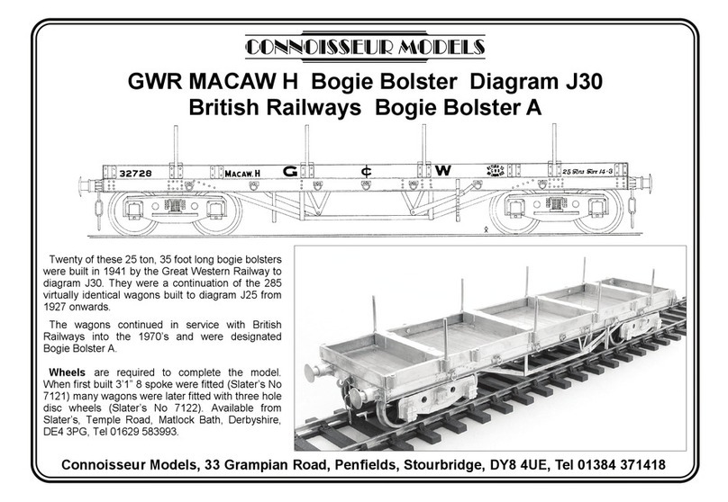
Connoisseur Models GWR MACAW H User manual

Connoisseur Models
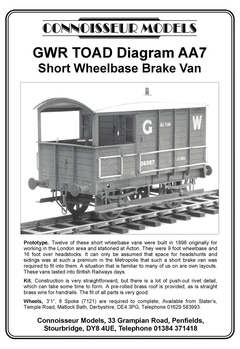
Connoisseur Models GWR TOAD Diagram AA7 User manual

Connoisseur Models
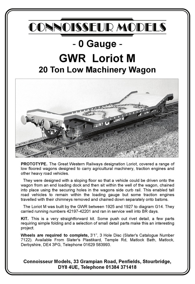
Connoisseur Models GWR Loriot M User manual

Connoisseur Models
Connoisseur Models LNER Class G5 0-4-4 Tank User manual

Connoisseur Models
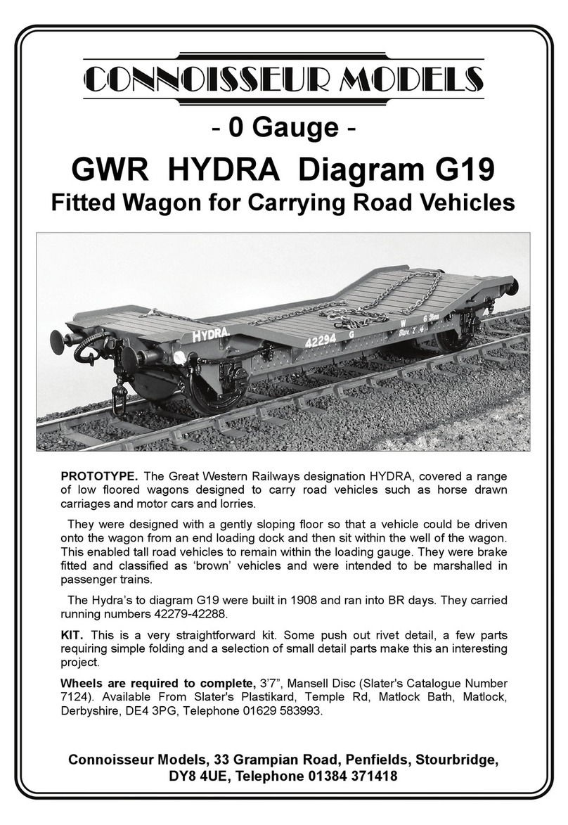
Connoisseur Models GWR HYDRA Diagram G19 User manual

Connoisseur Models
Connoisseur Models train User manual

Connoisseur Models
Connoisseur Models GWR MACAW B Bogie Bolster Diagram J28British Railways Bogie Bolster... User manual

Connoisseur Models
Connoisseur Models LNER Toad E User manual

Connoisseur Models
Connoisseur Models Six Wheeled All Third Coach User manual