Consort SLPIR Use and maintenance manual

1
Installation & Control Guide for SLPIR
Motion Detection Wireless Controller
All electrical appliances produced by the Company are guaranteed for one year against faulty materials or
workmanship. This applies only if the appliance has been used for purposes in accordance with the instructions
provided and has not been connected to an unsuitable electricity supply, or subject to misuse, neglect, damage
or modified or repaired by any person not authorised by us. This guarantee is offered to you as an extra benefit and
does not affect your legal rights.
The correct electricity supply voltage is shown on the rating label attached to the appliance.
Reasonable care has been taken to ensure that this guide is accurate at the time of printing. In the interest of
progress the Company reserve the right to vary specifications from time to time without notice.
SLPIR CONTROLLER
13984111 Iss 01
CUSTOMER HELPLINE
Should you need any advice on the use of your new Consort product, please contact our Helpline:
Consort Equipment Products Limited
Thornton Industrial Estate, Milford Haven, Pembrokeshire, SA73 2RT
Operation hours: Mon to Thu 8.30am to 4.30pm | Fri 8.30am to 3.30pm
BS EN ISO 9001 Registered Company No FM12671

2
SLPIR
Motion Activated
Wireless Controller
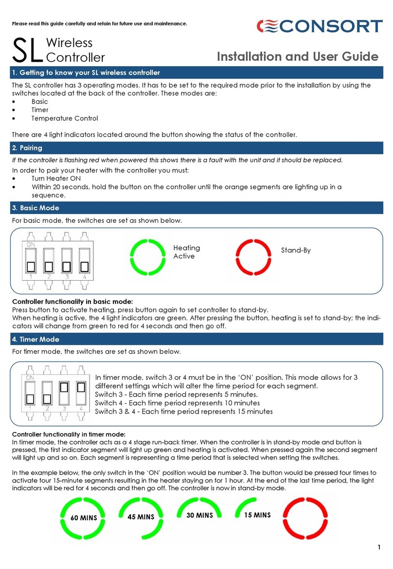
The SLPIR controller is designed to control multiple SL heaters or SL receivers within the RF range. The RF range can
be extended if necessary *see product code SLEXT. The controller has 2 operating modes. The required mode must
be set prior to the installation by using the switches located on the back of the controller. These modes are:
Motion detection with Timer
Motion detection with Timer and Temperature Control
There are 4 light indicators located around the sensor showing the status of the controller.
PLEASE NOTE: When powered, the controller will take approximately 30 seconds start up time to function. During this
period the light segments around the sensor will flash green. After this period the light segments will stop flashing
and the controller becomes fully functional.
Please read this guide carefully and retain for future use and maintenance.
Installation and User Guide
2. Getting to know your SL wireless controller
The switches 3 and 4 are used to set 4 different time settings for ON period after the
motion detection. The light segments around the sensor show remaining time.
Each segment equals 1/4 of the total time.
Switch 3 & 4 OFF - 5 minutes
Switch 3 ON - 15 minutes.
Switch 4 ON - 30 minutes
Switch 3 & 4 ON - 60 minutes
3. Presence detection with Timer
To set ON time period after the motion was detected, the switches are set as shown below.
60 MINS 45 MINS 30 MINS 15 MINS
Controller functionality :
After the motion detection, the controller acts as a run-back timer. Whenever motion is detected , all indicator segments
light up green and heating is activated for the set period of time. Each segment represents 1/4 of the time period that is
selected when setting switches 3 and 4.
In the example below, the switches 3 and 4 are set to ‘ON’ position. The total time of the ON period is 60 minutes. Each
segment represents 15 minutes. At the end of the last time period, the light segments will be red for 4 seconds and then go
off. The controller is now in stand-by mode.
WARNINGS
Do NOT handle the controller with wet hands.
Do NOT use the controller in workshops or rooms with high dust
exposure.
Do NOT cover or restrict any aperture.
Do NOT use the controller if damaged.
Do NOT leave the controller unattended where young children
are present.
Ensure that nothing is pushed into any aperture of this controller.
Operating temperature range -10 to +40ºC.

3
Room temperature below the set temperature.
Heating is active.
Variable resistors to
set temperature
Set temperature
achieved
Temperature control for comfort and setback periods can be used individually or together.
The temperature control feature will effectively maintain the set room temperature
within the time period. The target temperature can be set using the knob marked
COMF located at the back of the controller as shown below. The range is 15ºC - 35ºC.
Once the room temperature reaches the set temperature, the indicators will change
from green to orange. When the room temperature drops, heating will became
active and the indicators will change to green.
When the temperature control for setback period is enabled, the controller will
activate the heating when the room temperature drops below the set temperature.
This feature can be used for frost protection or in situations where a minimum room
temperature must be maintained. The setback temperature can be set using the
knob marked SETB mounted on the back of the unit as shown above. This can be set
from 0ºC - 15ºC.
Temperature control for Setback period
To enable temperature control for the setback period, the switch 2 is set to ‘ON’ position as shown below.
If the heating is active in the setback mode, the indicators will illuminate red and green.
Temperature control for the comfort period
To enable temperature control, the switch 1 is set to ‘ON’ position as shown below. The temperature control is only
active after motion detection and will end after the set time period ends. After the set time period ends, the tem-
perature is allowed to fall. If the room temperature is higher than the set comfort temperature, the heating will not
be activated after the motion detection.
4. Presence detection with Time and Temperature Control
The temperature and/or timer settings can be changed after installation. It is important to switch the power off to
the controller before the changes are made. After the changes are made and the power is restored the new
settings will take effect.
5. Changing temperature or timer settings after installation
The controller can be deactivated by using any external device with voltage free contacts.
For example, timers or a building management system.
If this function isn’t used, a wire link across the external input connectors must be used.
When the external input connection is open, the indicators will light up red and the
presence detection and heating will be disabled. However, setback mode will still operate
at low temperature.
6. External Input
The PIR detection range is up to 5 metres. The detection area is 60 degrees vertical and 120 degrees horizontal.
This can be tested in the test mode after the pairing. Check the Pairing section for more details explaining the test
mode.
7. PIR Detection Range

4
9. Installation
The controller is designed to fit onto most single gang back boxes. When a metal box is used this must be earthed.
The controller can be powered by either mains 240VAC 50Hz or 12VDC. The power consumption is less than 1W. Do
not connect mains voltage to 12V terminals, this will damage the controller. The maximum size wire that can be
used is 1mm2, this can be twin and earth or standard flex . Do not overtighten the connector screws. Take care not
to damage the components when connecting the cables.
WARNING, this controller is not compatible with single gang metal back box with 4 fixing lugs.
10. Connection to the Main Supply
For the mains power, connect Line and Neutral wires to the connectors marked L and N.
Electrical installation should be carried out by a competent installer, preferably registered with NICEIC (National
Inspection Council for Electrical Installation Contracting) in accordance with the 18th edition of the IEE Wiring
Regulations, (BS.7671), and any relevant Local Authority Bye-Laws.
Powering the controller with 12VDC allows the controller to be installed in a zone 2 area, however, the installation
must comply with the Separated Extra Low Voltage (SELV) requirements. When powered by 12VDC, please ensure
that the power supply is suitable for 12V 0.1A. For 12VDC power connect the positive wire to the terminal marked
+12V and negative to terminal marked –12V.
11. Connection to 12V DC
In order to pair your heater with the controller :
Isolate the controller and heater from the power
Follow the sequence below
Power ON the controller or controller and heater together
Wait 2 seconds
Power OFF the controller or controller and heater together
Wait 2 seconds
Power ON the controller or controller and heater together
Wait 2 seconds
Power OFF the controller or controller and heater together
Wait 2 seconds
Power ON the heater
Power ON the controller
If the sequence was followed correctly, the 4 light segments will flash yellow to indicate pairing
After the pairing is finished, the light segments will change to green.
If the pairing was successful, the appliance should emit heat. It can take up to 4 seconds.
After the light segments stop flashing the controller is in the test walk mode to allow testing of the functions. In this
mode the time delay is automatically set to 10 seconds.
In order to enter normal operation mode turn power to the controller OFF for 2 seconds and back ON.
8. Choosing a position in a room
The SLPIR controller should be fixed to the wall or ceiling. If installed on the wall it should be positioned at 1.5 metres
from the floor pointing towards the detection area. If mounted on the ceiling the orientation to achieve the best
detection should be used. Check the detection range section for more details. Avoid areas with a draught, direct
sun or opposite windows. Do not position the controller above or close to the heaters or other heat sources. Damp
areas or areas where the SLPIR can be mechanically damaged should also be avoided. Avoid installing the
controller in areas where there are metal objects between the heater and the controller. These will reduce the RF
range. The RF range in ideal conditions can be up to 20m however this can be reduced when the signal is passing
through walls or other objects. The range can be also affected where the controller is mounted close to power
cables, motors or equipment producing a strong electromagnetic field. If the temperature control feature is used it
is necessary to use one controller for each room or zone.
L
N
Mains Connection
230/240V AC 50Hz
+
-
12V DC
12. Pairing
Table of contents
Other Consort Controllers manuals

Consort
Consort MRX1 User manual

Consort
Consort CRXSL-05 User manual

Consort
Consort SL User manual

Consort
Consort HRXSL Use and maintenance manual

Consort
Consort CRX1 User manual

Consort
Consort CRXLC User manual

Consort
Consort CRX2-03 User manual

Consort
Consort SLTI Use and maintenance manual

Consort
Consort SLVTB Use and maintenance manual

Consort
Consort SLPBWIFI Use and maintenance manual