2
Switch 1 controls the display screen. If it is set to ’ON’ the temperature is displayed as
Fahrenheit. If it is set to ‘OFF’ the temperature is displayed as Celsius.
Prior to installation the maximum comfort temperature must be set by using the knob marked
COMF located at the back of the controller as shown below. The range is 15°C to 35°C. The
maximum comfort temperature limits the comfort temperature that can be set by users after
installation. After installation, the user can adjust the comfort temperature using the UP and
DOWN buttons, in the range from 15°C up to the maximum comfort temperature set by the
knob marked COMF.
After pressing the on button the heating will operate until the set room temperature is
achieved, at this point the ‘h’ indicator on the display will start flashing. When the room
temperature drops the heating will become active again and the ‘h’ indicator will change
from flashing to steadily on.
The display screen will show the actual room temperature, except briefly when either of the
two adjustment buttons are pressed, the new target room temperature is then temporarily
displayed.
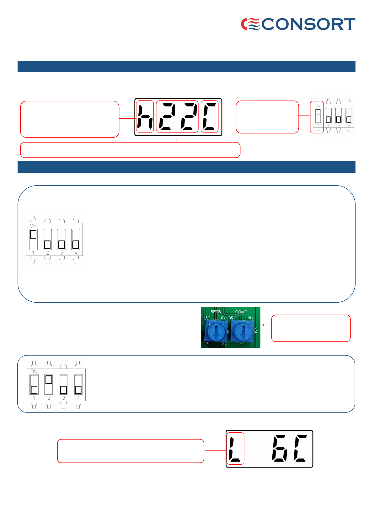
SLVTB Wireless
Controller
Temperature can be
displayed in °C or °F.
This can be changed
by SW1.
Please read this guide carefully and retain for future use and maintenance.
Installation and User Guide
1. Getting to know your SLVTB wireless battery powered controller
2. Temperature Control Mode
Temperature control for Comfort period
Symbol ‘L’ is flashing. Room temperature is below the
set temperature. Heating is active.
Temperature control for comfort and setback periods can be used individually or together. This can also be used in
conjunction with the timer mode options.
In this mode, the controller will set heating active when the room temperature
drops below the set temperature. This feature can be used for frost protection or in
situations where a minimum room temperature must be maintained. The setback
temperature can be set using the knob marked SETB mounted on the back of the
unit as shown above. This can be set from 0ºC - 15ºC.
Temperature control for Setback period
For this mode, the switches are set as shown below.
Variable resistors to set
maximum comfort and
setback temperatures
If the heating is active in the setback mode, the display will show letter ‘L’ that is flashing.
Heating status :
h -heating active
h flashing - heating inactive, room
at set temperature
h not shown -heating inactive
Temperature not flashing : indicating room temperature
Temperature flashing : indicating set temperature when using UP or DOWN buttons
The SLVTB controller can control an unlimited number of heaters. The controller has 2 operating modes. It has to be
set to the required mode prior to the installation by using the switches located at the back of the controller. The
controller is powered by two AAA batteries. The heating status and the room temperature are displayed.
NOTE :
After changing any settings, in order for the change to take
place, the controller has to be set to heating inactive status.


