6
Current 1A 2A 3A 4A 5A 6A 7A 8A 9A 10A
Cable Type Cable Length
Maximum
Cable
Length
Round
Cable
(CSA)
1mm21319m 659m 440m 330m 264m 220m 188m 165m 147m 132m
1.5mm21547m 773m 516m 387m 309m 258m 221m 193m 172m 155m
2.5mm21739m 870m 580m 435m 348m 290m 248m 217m 193m 174m
Flat
Cable
(Width)
10mm 979m 489m 326m 245m 196m 163m 140m 122m 109m 98m
12.5mm 1851m 925m 617m 463m 370m 308m 264m 231m 206m 185m
25mm 2450m 1225m 817m 613m 490m 408m 350m 306m 272m 245m
Double-Turn Loop
Single-Turn Loop
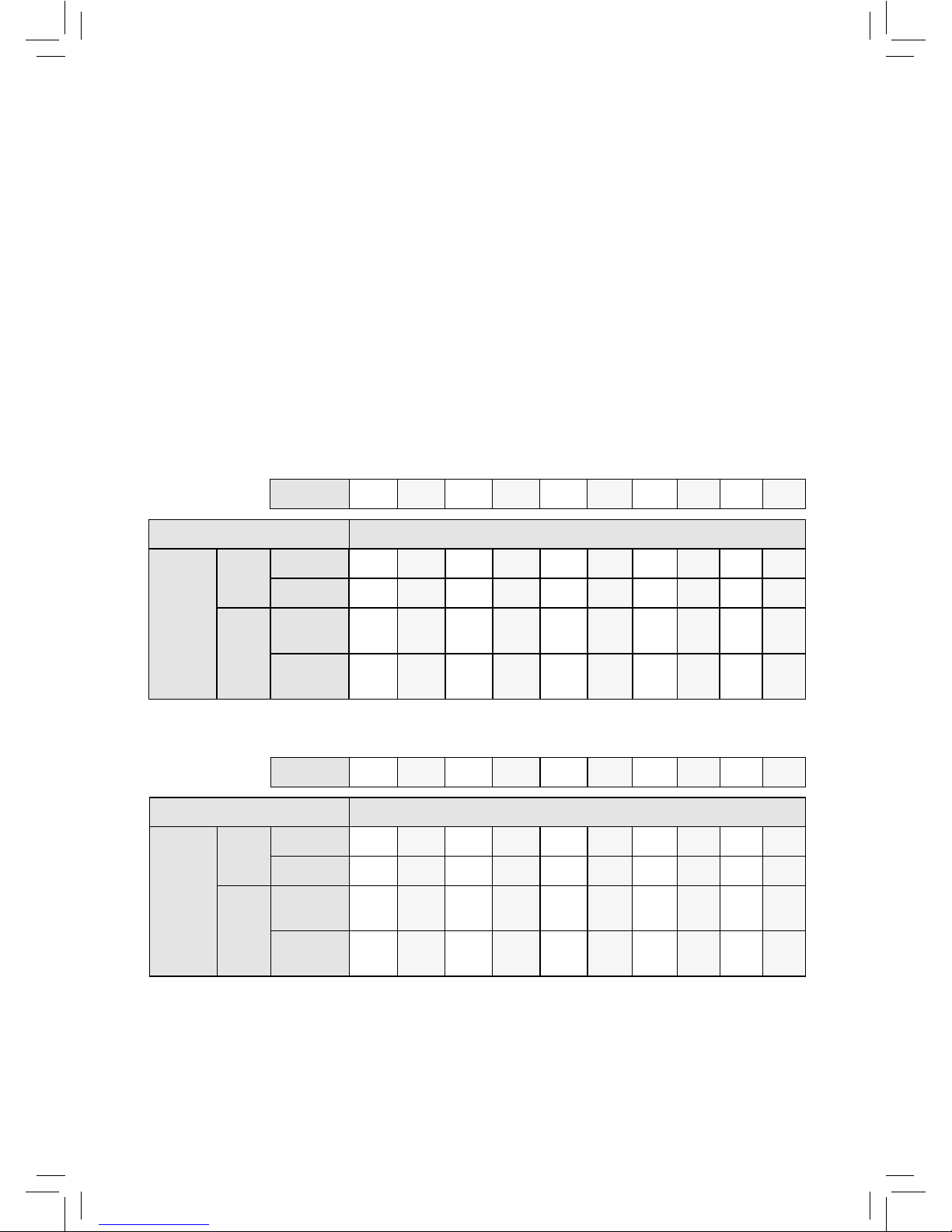
The tables in this section show the metric maximum cable lengths for
dierent maximum required currents.
No clipping below 1.6kHz (IEC specications):
Example:
If an installed cable is 520m of 25mm at single turn and the
required current noted in Step 3 (7) of Set-Up (see page 14) is 5
amps or greater, the driver is clipping.
Suitable Cable Lengths (Metric)
Current 1A 2A 3A 4A 5A 6A 7A 8A 9A 10A
Cable Type Cable Length
Maximum
Cable
Length
Round
Cable
(CSA)
1mm2959m 479m 320m 240m 192m 160m 137m 120m 107m 96m
1.5mm21036m 518m 345m 259m 207m 173m 148m 130m 115m 104m
2.5mm21089m 544m 363m 272m 218m 181m 156m 136m 121m 109m
Flat
Cable
(Width)
10mm 856m 428m 285m 214m 171m 143m 122m 107m 95m 86m
12.5mm 1324m 662m 441m 331m 265m 221m 189m 166m 147m 132m
25mm 1568m 784m 523m 392m 314m 261m 224m 196m 174m 157m
The tables in this section show the metric maximum cable lengths for
dierent maximum required currents.
No clipping below 1.6kHz (IEC specications):
Example:
If an installed cable is 166m of 1.5mm² (round) single turn and
the required current noted in Step 3 (7) of Set-Up (see page 14)
is 4 amps or greater, the below table indicates that the driver
is clipping. If the required current noted in Step 3 (7) is less
than 4 amps, the driver is not clipping.