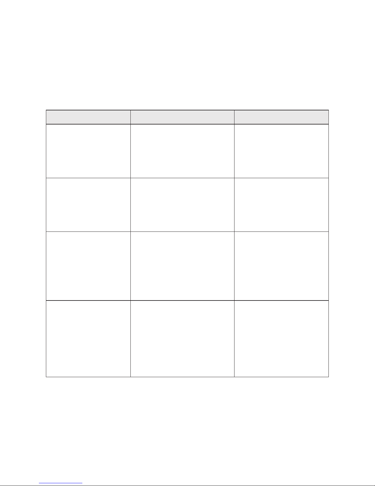
Contacta V12a Operation manual

1
V7 / V12a
Installation &
User Guide
October 2017
Hearing Loop Drivers

2
Contents
Product Overview
Components
Connections
Start-Up Tests
Controls Overview
Hearing Loop Setup
Suitable Cable Lengths
Troubleshooting
Technical Specications
Standards
3
4
5
7
8
17
21
23
24
26
Contacta has a policy of continuous product development, therefore small specication changes
may not be reected in this manual. Images, labels, packaging, accessories and product colours
are subject to change without notice.

3
Product Overview
Our highly eicient and compact V7 and V12a hearing loop drivers are
suitable for smaller facilities and venues.
The V7 is a constant current hearing loop driver which powers
perimeter hearing loops. The V12a is a constant current dual output
hearing loop driver with integral phase shifter for phased array
conguration.
Both hearing loop drivers have Class-D amplier output stages and an
audio subsystem built around an advanced DSP core. Combined with
a powerful CPU that ensures peak performance, they use cutting edge
technology proven in the pro audio world to achieve life-like speech
and rst-class music reproduction.
Note: For large area hearing loop installation instructions, consult the
Large Area Hearing Loop Installation Guide.

4
Components
1. Rubber Feet x4
2. 5.08mm Euro-Block Connector
3. 3.81mm Euro-Block Connector x2
4. Signage
5. V7 Hearing Loop Driver
6. Installation & User Guide
7. Power Supply [PS-55]
8. IEC Power Lead
Cable & Equipment: A length of loop cable determined by the loop
design is also required. Hearing loop drivers also require ancillary
equipment for audio feeds, such as a microphone or sound system.
5
6
1. Rubber Feet x4
2. 5.08mm Euro-Block Connector x2
3. 3.81mm Euro-Block Connector x2
4. Signage
5. V12a Hearing Loop Driver
6. Installation & User Guide
7. Power Supply [PS-60]
8. IEC Power Lead
48
7
V7
V12a
123
5
6
48
7
123

5
1. Microphone Input - 3.81mm Euro-block balanced microphone
input (12V phantom power via 680Ω).
2. Line Input 1 - 3.81mm Euro-block balanced line input/feedthrough.
3. Line Input 2 - XLR balanced line input/feedthrough.
4. Power Supply Input - *V7 DC Power Input, 2.1mm 14Vdc 2.14A
**V12a DC Power Input, 2.1mm 24Vdc 4.17A.
Caution: Use only the provided Power Supply.
5. Loop A Output - 5.08mm Euro-block.
6. Loop B Output - 5.08mm Euro-block [V12a only].
Rear Panel Connections
Connections
1 2 3456
Note: Only connect to one Line Input at a time.

6
Connection Examples
XLR to XLR (line)
TRS to XLR (line)
Unbalanced to XLR
XLR to Euroblock (balanced)
Unbalanced to Euroblock

7
Start-Up Tests
V Series drivers perform a series of tests when powered on, causing a
number of indications to appear on the display screen during start-up.
The meanings of these indications are as follows:
Indicator Meaning Remedy
V7:
Loop Good
V12a:
Loop A Good
Loop B Good
Hearing loop(s) is/are correctly
connected to the driver.
None required.
V7:
Loop Open Fault
V12a:
Loop A Open Fault
Loop B Open Fault
Hearing loop(s) is/are improperly
connected to the driver.
An open-circuit loop will not
damage the driver, and start-up
will continue to the main menu.
Ensure that the loop(s) is
properly connected to the
driver. The loop current
indication in normal
operation may be used to
conrm the connections.
V7:
Loop Ground Fault
V12a:
Loop A Ground Fault
Loop B Ground Fault
A ground fault with the hearing
loop(s) has been found.
The driver will halt operation
with this message displayed on
screen, as such a fault would
cause stress to the driver were
normal operation to continue.
Switch o the driver and
carefully check the loop(s) for
shorts to ground. Rectify the
faults and re-apply power to
the driver.
Incorrect Power The power input supply voltage
from the mains power supply is
incorrect.
The driver will halt operation
with this message displayed on
screen, as such a fault would
cause stress to the driver were it
to continue to normal operation.
Switch o the driver and
connect the power supply
which was provided with the
driver. If this is not available,
contact your distributor to
order a new power supply.
Please note if using V12a: If connecting only one loop to a V12a, whichever loop connection
has not been used (either Loop A or Loop B) will show as an “Open Fault” as default. This is the
correct display for operation with only one loop; continue as normal.

8
Front Panel Overview
Controls Overview
1. Clip Status Light - When lit, this status LED indicates the signal on
the hearing loop output is clipping (see Troubleshooting on page
23 for appropriate solutions).
2. Display Screen - Indicates the status of the Loop Output, displays
menu and adjustment options.
3. Control Dial - Used for unlocking and making adjustments to the
V7.
V7
1. Clip Status Light - When lit, this status LED indicates the signal
on Hearing Loop A is clipping (see Troubleshooting on page 23 for
appropriate solutions).
2. Clip Status Light - When lit, this status LED indicates the signal
on Hearing Loop B is clipping (see Troubleshooting on page 23 for
appropriate solutions).
3. Display Screen - Indicates the status of the Loop Output, displays
menu and adjustment options.
4. Control Dial - Used for unlocking and making adjustments the
V12a.
V12a
12
3
1 2
4
3

9
Modes
Main Menu
After being unlocked, the hearing loop driver will display the main
menu. This is indicated by up and down arrows on the display screen.
V7
1. Loop Output
2. Line Input
3. Phantom Power
4. Microphone Input
5. Current Output
6. High-Frequency Compensation
V12a
1. Loop Output
2. Line Input
3. Phantom Power
4. Microphone Input
5. Loop B Trim Adjustment
6. High-Frequency Compensation
When in this mode, rotating the hearing loop driver’s control dial
clockwise will move the screen to the next menu item and rotating the
dial anti-clockwise will move it to the previous menu item.
The menu options are as follows:
The hearing loop driver will power up in Output Current Display Mode
and will be locked from entering Adjustment Mode.
1. To unlock the hearing loop driver, press the control dial and when
prompted “Unlock driver?” click “Yes.”
2. Enter the passcode 2239:
a. Rotate the control clockwise to select the rst required digit.
b. Press the control dial in to select the digit.
c. Repeat steps (a) and (b) until all the digits have been selected.
Note: Entering the wrong code returns the hearing loop driver to the
lock screen.
Unlocking the Hearing Loop Driver

10
Adjustment Mode
Press the control dial in to enter Adjustment Mode; the arrows on the
display screen will move to a left and right position.
Rotate the dial clockwise or anti-clockwise to make the adjustment.
Press the control dial in to conrm the selection and return to the main
menu.
If the control dial is not used for 120 seconds when in Adjustment
Mode the hearing loop driver will revert to the main menu, with Loop
Output as the default screen.

11
V7 Loop Output V12a Loop Output
V7 Loop Output: Adjustment Mode V12a Loop Output: Adjustment Mode
Adjustments
Loop Output
In Adjustment Mode, the real-time output current is displayed on the
top line in 0.5A steps. The bottom line indicates the strength of the
loop output level adjustment.
To alter the loop output level, enter Adjustment Mode:
• To increase the loop output level, rotate the control dial clockwise.
• To decrease the loop output level, rotate the control dial
anti-clockwise.
• Press the control dial once to conrm the selection and return to
the main menu.
The hearing loop driver’s Loop Output section displays the real-time
output current in 0.5A steps.

12
Adjustments
It is recommended that at least 5 blocks in the adjustment block are
lled (see the above image for an example).
Enter Adjustment Mode, and alter the line input level displayed on the
bar until the text displays ‘Good’:
• To increase the line input level, rotate the control dial clockwise.
• To decrease the line input level, rotate the control dial
anti-clockwise.
• Press the control dial once to conrm the selection and return to
the main menu.
Line Input
The hearing loop driver’s Line Input section displays the line input
level within a range of 47dB.
The text on the display indicates if the correct line level has been
achieved:
• “Low” indicates the line level is too low for the automatic gain
control to operate.
• “Good” indicates the line level is at an optimum level for the
automatic gain control to operate.
• “High” indicates the line level is too high and signal clipping may
occur. Signal clipping will also be shown by the LED.

13
Adjustments
Phantom Power
Rotating the control dial clockwise or anti-clockwise in Adjustment
Mode will toggle the phantom power on or o. Press the control dial
once to conrm the selection and return to the main menu.
Phantom power for a connected microphone is set o as the default
setting.

14
It is recommended that at least 5 blocks in the adjustment block are
lled (see the above image for an example).
Enter Adjustment Mode and alter the microphone input level
displayed on the bar until the text displays ‘Good’:
• To increase the microphone input level, rotate the control dial
clockwise.
• To decrease the microphone input level, rotate the control dial
anti-clockwise.
• Press the control dial once to conrm the selection and return to
the main menu.
The hearing loop driver’s Microphone Input section displays the
microphone input level within a range of 47dB.
The top line of the display indicates if the correct microphone input
level has been achieved:
• “Low” indicates the microphone level is too low for the automatic
gain control to operate.
• “Good” indicates the microphone level is at an optimum level for
the automatic gain control to operate.
• “High” indicates the microphone level is too high and signal
clipping may occur. Signal clipping will also be shown by the LED.
Adjustments
Microphone Input

15
V12a Only: Loop Trim
When using a V12a, the hearing loop driver’s Loop Trim function allows
Loop B’s output to be adjusted relative to Loop A’s output.
Please note: This section is only available on the V12a. The equivalent
V7 menu displays Current Output, to which adjustments can be made
using the Loop Output section (see page 11).
-
When in the Loop Trim section, adjustments are made in 1dB steps.
The measured loop output current is displayed in amps RMS (accurate
for sine signals).
Adjustments
Enter Adjustment Mode to alter “Loop B Trim” relative to “Loop A”.
• To increase the Loop B Trim level, rotate the control dial clockwise.
• To decrease the Loop B Trim level, rotate the control dial
anti-clockwise.
• Press the control dial once to conrm the selection and return to
the main menu.

16
There are 7 levels of high-frequency compensation available to adjust
for metal loss. Your hearing loop driver will have high-frequency
compensation turned to the lowest setting as its default.
Adjustments
To alter the high frequency compensation level, enter Adjustment
Mode:
• To increase the high-frequency compensation level, rotate the
control dial clockwise.
• To decrease the high-frequency compensation level, rotate the
control dial anti-clockwise.
• Press the control dial once to conrm the selection and return to
the main menu.
To calculate the correct high-frequency compensation level, refer to
page Hearing Loop Setup (Step 1: Metal Loss) on page 17.
High-Frequency Compensation

17
Hearing Loop Setup
• Contacta Test Signal Generator (TSG)
• Contacta Field Strength Meter (FSM) + Tripod
Required Equipment
Consult the Connections section on page 5 and the Controls Overview
section on page 8 before proceeding with setup, which should be
performed in following order:
Step 1: Metal Loss (see below)
Step 2: Output Level and Clipping (see page 19)
Step 3: Field Uniformity (see page 20)
Step 4: Final Output Level Adjustment (see page 20)
Step 1: Metal Loss
1. Connect hearing loop cables to the Loop Output connection(s) on
the rear of the driver.
2. Set up the FSM on a tripod to the following height inside the
hearing loop, dependent on the position of end users:
• 1.2 metres (3.9 feet) for seated user.
• 1.7 metres (5.6 feet) for standing users.
3. Connect the TSG to the Line Input of the hearing loop driver.
4. Set the TSG to the 1kHz setting.
5. Set the FSM to the Third Octave F= 1000Hz setting.
6. Power on the hearing loop driver.
7. Scroll to the Line Input section of the hearing loop driver display.
8. If the top bar of the Line Input section does not display ‘Good’,
enter Adjustment Mode and raise the Line Input level until ‘Good’
appears.

18
9. Scroll to the Loop Output section of the hearing loop driver
display, enter Adjustment Mode and change the loop output
current to 2ARMS (4 bars on the display screen = Just ON).
11. If using a V12a:
a. Place the tripod in the centre of a segment of the hearing loop
which is connected to the hearing loop driver’s Loop A output
port. Take a note of the value measured by the FSM.
b. Place the tripod in the centre of a segment of the hearing loop
which is connected to the hearing loop driver’s Loop B output
port. Take a note of the value measured by the FSM.
c. Conrm the recorded values are within 3dB of each other.
d. If the recorded values are not within 3dB of each other, scroll
to the Loop Trim B section of the hearing loop driver, enter
Adjustment Mode and adjust the loop output currents to
2ARMS.
e. Conrm the FSM readings are now within 3dB of each other
and note their values.
12. Set the TSG to the 5kHz setting.
13. Set the FSM to the Third Octave F= 5000Hz setting.
14. Take note of the value measured by the FSM in the previously
measured positions:
a. If the dierence is less than 3dB, proceed to Step 2: Output
Level and Clipping.
b. If the dierence between the values measured at 1kHz
and 5kHz is greater than 3dB, adjust the High-Frequency
compensation:
i. Scroll to the High-Frequency Compensation section of the
hearing loop driver display and enter Adjustment Mode.
ii. Increase the High-Frequency Compensation.
iii. Set the TSG to 1kHz and FSM to Third Octave F= 1000Hz
setting.
iv. Repeat steps 12 to 14.

19
Step 2: Output Level and Clipping
1. Set the TSG to the 1kHz setting.
2. Set the FSM to the RMS/Peak A-Weighted Mode and place it on a
tripod to the following height inside the hearing loop, dependant
on the position of end users:
• 1.2 metres (3.9 feet) for seated user.
• 1.7 metres (5.6 feet) for standing users.
Note the FSM’s position when on the tripod, as this will be used
again in Step 4: Final Output Level Adjustment.
3. In the Loop Output section of the hearing loop driver, enter
Adjustment Mode and increase the drive level until the FSM
measures 0dB +/- 0.5dB as follows:
A-RMS: +0.0dB
Peak: +3dB
Note: there is no need to go higher than +0dB A-RMS.
4. Make a note of the current required to achieve the required eld
strength.
5. Set the TSG to 1.6kHz.
6. Conrm that the Clipping Status Light(s) remains unlit. If so,
proceed to Step 3: Field Uniformity.
7. If the Clipping Status Light(s) remains lit, the hearing loop driver
is clipping and the connected hearing loop is too long and the
system will not meet requirements of IEC 60118-4.
Perform the following solutions until the Clipping Status Light has
turned o:
• Reduce the length of the loop.
• Use a larger diameter cable.
• Create a two-turn loop.
• Use a higher voltage hearing loop driver.
8. Once the Clipping Status Light has turned o, proceed to Step 3:
Field Uniformity.

20
Step 3: Field Uniformity
1. Set up the FSM on a tripod to the following height inside the
hearing loop, dependant on the position of end users:
• 1.2 metres (3.9 feet) for seated user.
• 1.7 metres (5.6 feet) for standing users.
2. In the Loop Output section of the hearing loop driver, enter
Adjustment Mode and reduce the loop output current to 2 amps.
3. Set the FSM to the RMS/Peak A-Weighted Mode and note the
measured value.
4. Move the FSM to another position within the looped area and note
the measured value.
5. The dierence measured in the second position should not be
greater than +/- 3dB of that measured in the rst position. Repeat
steps 3 and 4 to create a suitable map of the looped area.
6. Proceed to Step 4: Final Output Level Adjustment.
Step 4: Final Output Level Adjustment
1. Set up the FSM in the same position noted in Step 2: Output Level
and Clipping.
2. Set the TSG to 1kHz.
3. Adjust the output current to the level recorded in Step 2 (4).
4. Note the value recorded on the FSM – if the setup has been
performed correctly, this will be 0dB +/- 0.5dB.
5. Hearing loop setup is complete.
This manual suits for next models
1
Table of contents
Other Contacta Hearing Aid manuals

Contacta
Contacta IL-RX30 Operation manual

Contacta
Contacta HLD9 User manual

Contacta
Contacta PRO Series Operation manual

Contacta
Contacta HLD3 User manual

Contacta
Contacta IL-K200 Operation manual

Contacta
Contacta HLD4 Operation manual

Contacta
Contacta IL-RX20 User manual

Contacta
Contacta HLD7 User manual

Contacta
Contacta IL-RX20 User manual

Contacta
Contacta IL-RX30 Operation manual