Contacta V Series Operation manual

1
V22
Installation &
User Guide
May 2021
Hearing Loop Driver

2
Contents
Product Overview
Components
Connections
Suitable Cable Lengths
Driver Area Coverage
Controls
Hearing Loop Setup
Troubleshooting
Warning / Error Messages
Technical Specications
3
4
5-6
7-8
9
10-18
19-24
25
26
28
Contacta has a policy of continuous product development, therefore small specification
changes may not be reflected in this manual. Images, labels, packaging, accessories and
product colors are subject to change without notice.

3
Product Overview
Our highly eicient V22 hearing loop driver is built around high-end
technology designed for the agship V Series PRO hearing loop driver
range. It is suitable for driving the most demanding perimeter loop
systems in medium to large venues.
With a Class-D amplier output stage, the V22 delivers a high enough
current to drive even the toughest loop loads.
The audio subsystem is built around an advanced DSP core. Combined
with a microprocessor control that ensures peak performance, the
driver uses cutting edge technology to deliver peak performance.
Note: For large area hearing loop installation instructions, consult the
Large Area Hearing Loop Installation Guide.

4
*Plug type varies by country.
Cable & Equipment: A length of loop cable determined by the loop
design is also required. Hearing loop drivers also require ancillary
equipment for audio feeds, such as a microphone or sound system.
Components
1. Rubber Feet x 4
2. 2-way 3.5mm Euro-Block Connector x 2
3. 3-way 3.5mm Euro-Block Connectors x3
4. 4-way Terminal Block
5. Hearing Loop Stickers
6. V22 Hearing Loop Driver
7. User Guide
8. IEC Power Lead*
9. Rack Mounting Ears
10. Compliance Certicate
6
8
1
2
7
47
10
3
8
9
445

5
1. Power Supply Input
*
2.
Factory Use (no user input)
3.
Line Input - 3.5mm Euro-block balanced line input
4.
100V Line Input - 3.5mm Euro-block transformer isolated &
balanced
5.
MP3 (Line Input)- 3.5mm Euro-block transformer isolated &
balanced
6.
Line/Microphone - Switchable phantom power (12V) XLR
7.
Line Output – 3.5mm Euro-block
8.
Loop Output - 5.08mm 4-way terminal block
Connections
*Power Sources - This product should be operated only from the type
of power source indicated on the marking label. If you are not sure of
the type of power supply to your home, consult your product dealer or
local power company. The primary method of isolating the amplier
from the mains supply is to disconnect the mains plug. Ensure that the
mains plug remains accessible at all times. Unplug the AC power cord
from the AC outlet if the unit will not be used for several months or
more.

6
Connection Examples
XLR to Euroblock (balanced)
Unbalanced to Euroblock
Isolated and Balanced

7
Suitable Cable Lengths
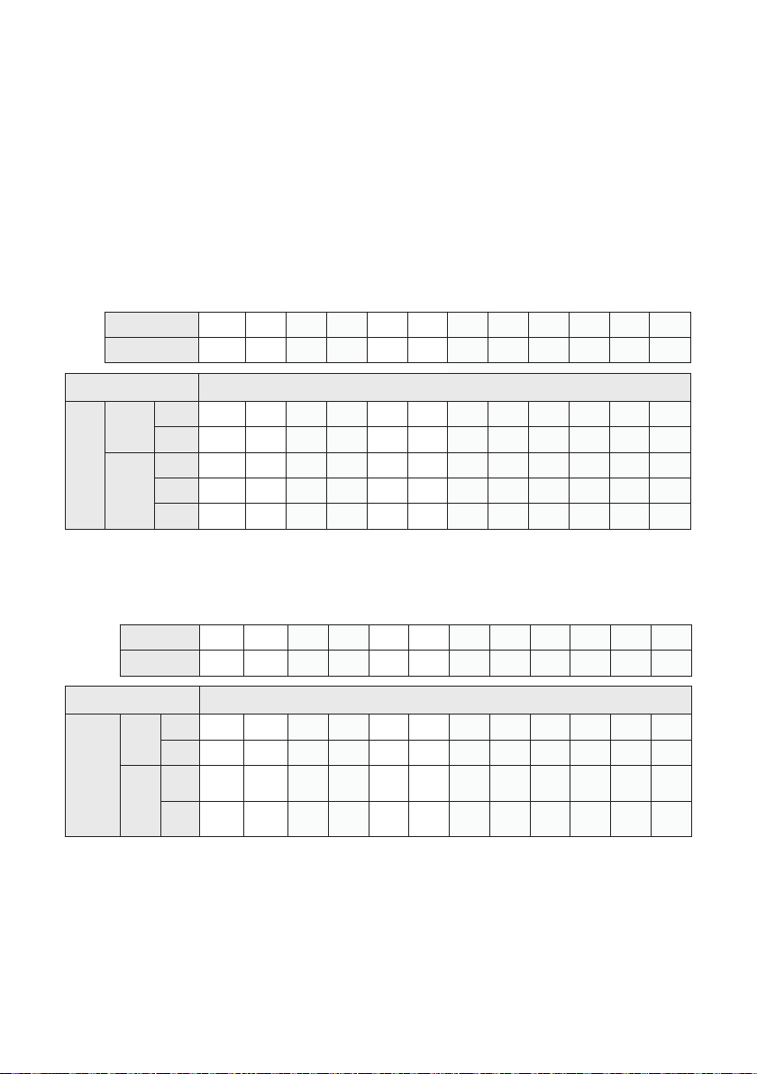
The tables in this section show the approximate maximum cable
lengths for diering maximum required currents to achieve a
400mA/m eld strength.
Loop impedance (at 1.6kHz) should be less than voltage capability of
the driver (22V) divided by the required current.
V22 Single-Turn (Metric)
Current 1A 2A 3A 4A 5A 6A 7A 8A 9A 10A 11A 12A
Impedance 22.6Ω11.3Ω7.53Ω5.65Ω4.52Ω3.77Ω3.23Ω2.83Ω2.51Ω2.26Ω2.05Ω1.88Ω
Cable Type Cable Length
Max.
Cable
Length
Round
Cable
(AWG)
1.5mm 970.99m 485.50m 323.66m 242.75m 194.20m 161.83m 138.71m 121.37m 107.89m 97.10m 88.27m 80.92m
2.5mm 1091.74m 545.87m 363.91m 272.94m 218.35m 181.96m 155.96m 136.47m 121.30m 109.17m 99.25m 90.98m
Flat Cable
(Width)
10mm 614.41m 307.21m 204.80m 153.60m 122.88m 102.40m 87.77m 76.80m 68.27m 61.44m 55.86m 51.20m
12.5mm 1161.97m 580.99m 387.32m 290.49m 232.39m 193.66m 166.00m 145.25m 129.11m 116.20m 105.63m 96.83m
25mm 1538.27m 769.13m 512.76m 384.57m 307.65m 256.38m 219.75m 192.28m 170.92m 153.83m 139.84m 128.19m
V22 Single-Turn (Imperial)
Current 1A 2A 3A 4A 5A 6A 7A 8A 9A 10A 11A 12A
Impedance 22.6Ω11.3Ω7.53Ω5.65Ω4.52Ω3.77Ω3.23Ω2.83Ω2.51Ω2.26Ω2.05Ω1.88Ω
Cable Type Cable Length
Max.
Cable
Length
Round
Cable
(AWG)
18AWG 2552.86ft 1276.43ft 850.95ft 638.21ft 510.57ft 425.48ft 364.69ft 319.11ft 283.65ft 255.29ft 232.08ft 212.74ft
14AWG 3408.47ft 1704.23ft 1136.16ft 852.12ft 681.69ft 568.08ft 486.92ft 426.06ft 378.72ft 340.85ft 309.86ft 284.04ft
Flat
Cable
(Width)
18AWG
(equiv.)
2871.76ft 1435.88ft 957.25ft 717.94ft 574.35ft 478.63ft 410.25ft 358.97ft 319.08ft 287.18ft 261.07ft 239.31ft
14AWG
(equiv.)
4538.17ft 2269.08ft 1512.72ft 1134.54ft 907.63ft 756.36ft 648.31ft 567.27ft 504.24ft 453.82ft 412.56ft 378.18ft

8
V22 Double-Turn Hearing Loop (Metric)
Current 1A 2A 3A 4A 5A 6A 7A 8A 9A 10A 11A 12A
Impedance 22.6Ω11.3Ω7.53Ω5.65Ω4.52Ω3.77Ω3.23Ω2.83Ω2.51Ω2.26Ω2.05Ω1.88Ω
Cable Type Cable Length
Max.
Cable
Length
Round
Cable
(AWG)
1.5mm 650.61m 325.31m 216.87m 162.65m 130.12m 108.44m 92.94m 81.33m 72.29m 65.06m 59.15m 54.22m
2.5mm 683.46m 341.73m 227.82m 170.87m 136.69m 113.91m 97.64m 85.43m 75.94m 68.35m 62.13m 56.96m
Flat Cable
(Width)
10mm 537.58m 268.79m 179.19m 134.39m 107.52m 89.60m 76.80m 67.20m 59.73m 53.76m 48.87m 44.80m
12.5mm 831.19m 415.60m 277.06m 207.80m 166.24m 138.53m 118.74m 103.90m 92.35m 83.12m 75.56m 69.27m
25mm 984.36m 492.18m 328.12m 246.09m 196.87m 164.06m 140.62m 123.05m 109.37m 98.44m 89.49m 82.03m
V22 Double-Turn Hearing Loop (Imperial)
Current 1A 2A 3A 4A 5A 6A 7A 8A 9A 10A 11A 12A
Impedance 22.6Ω11.3Ω7.53Ω5.65Ω4.52Ω3.77Ω3.23Ω2.83Ω2.51Ω2.26Ω2.05Ω1.88Ω
Cable Type Cable Length
Max.
Cable
Length
Round
Cable
(AWG)
18AWG 1864.96ft 932.48ft 621.65ft 466.24ft 372.99ft 310.83ft 266.42ft 233.12ft 207.22ft 186.50ft 169.54ft 155.41ft
14AWG 2131.29ft 1065.65ft 710.43ft 532.82ft 426.26ft 355.22ft 304.47ft 266.41ft 236.81ft 213.13ft 193.75ft 177.61ft
Flat
Cable
(Width)
18AWG
(equiv.)
2254.91ft 1127.45ft 751.64ft 563.73ft 450.98ft 375.82ft 322.13ft 281.86ft 250.55ft 225.49ft 204.99ft 187.91ft
14AWG
(equiv.)
2958.49ft 1479.24ft 986.16ft 739.62ft 591.70ft 493.08ft 422.64ft 369.81ft 328.72ft 295.85ft 268.95ft 246.54ft

9
Driver Area Coverage
Note:A full site survey of an installation area is recommended for
optimal loop design.
Areas detailed in the table below are valid only when the following
conditions are met:
1. Area is at the maximum current the driver is capable of delivering
without voltage clipping at 1.6KHz
2. Loop layout is designed to achieve 0dB in the centre
3. 25mm x 0.1mm at copper cable
4. Loop is installed in the oor
5. Listening height 1.2m (large perimeter loops may have areas where
the actual signal level is higher than required)
Area
Voltage Current 1:1 1:2 1:3
22V 12A 715.0sqm 899.0sqm 961.0sqm
7692.0sqft 9672.0sqft 10338.0sqft

10
Front Panel Overview
Controls
1. Clip Status Light - When lit, this status LED indicates the signal on
the hearing loop output is clipping (see Troubleshooting on page
25 for appropriate solutions).
2. Open Circuit Loop - Indicates the status of the Loop integrity
3. Display Screen - Indicates the status of the Loop Output, displays
menu and adjustment options.
4. Control Dial - Used for unlocking and making adjustments.
1
2 3
When power is applied the hearing loop driver will automatically
perform an analysis of the loop connected to the output.
When the analysis is complete, the following screen should display:
Start-Up Sequence
Rotating or pressing the control will display the unlock screen.
Should an error occur during start up, please consult warning and
error messages page 26.
4

11
The hearing loop driver will power up in Output Current Display Mode
and will be locked from entering Adjustment Mode.
Unlock the Driver
1. To unlock the hearing loop driver, press the control dial, and when
prompted “Unlock driver?” click “Yes.”
2. Enter the passcode 2239:
a. Rotate the control clockwise to select the rst required digit.
b. Press the control dial in to select the digit.
c. Repeat steps (a) and (b) until all the digits have been selected.
Note: Entering the wrong code returns the driver to the lock screen.
Locking/Unlocking the Hearing Loop Driver
Modes
Main Menu
After being unlocked, the hearing loop driver will display the main
menu. This is indicated by up and down arrows on the display screen.
When in this mode, rotating the hearing loop driver’s control dial
clockwise will move the screen to the next menu item and rotating the
dial anti-clockwise will move it to the previous menu item.
The menu options are as follows:
1. Loop Output
2. AGC On/O
3. Input A/Isolated
4. Input B [Phantom Power]
5. High Frequency Compensation
6. Input High Pass Filter

12
7. Acoustic Delay
8. Backlight Timeout
9. Diagnostics
Adjustment Mode
Press the control dial in to enter Adjustment Mode; the arrows on the
display screen will move to a left and right position. Rotate the dial
clockwise or anti-clockwise to make the adjustment. Press the control
dial in to conrm the selection and return to the main menu.
If the control dial is not used for 120 seconds when in Adjustment
Mode the hearing loop driver will revert to the main menu, with Loop
Output as the default screen.
Loop Output
The hearing loop driver’s Loop Output section displays the real-time
output current in 1A steps.
Locking/Rebooting the Unit
To lock the V22 when not in adjustment mode, press and hold the
control dial for 5 seconds.
If an error message is displayed, reboot the driver by pressing and
holding the control dial for 5 seconds.

13
In Adjustment Mode, the real-time output current is displayed on the
top line in 1A steps. The bottom line indicates the strength of the loop
output level adjustment.
To alter the loop output level, enter Adjustment Mode:
•To increase the loop output level, rotate the control dial clockwise.
• To decrease the loop output level, rotate the control dial
anti-clockwise.
•Press the control dial once to conrm the selection and return to
the main menu.
Rotating the control dial clockwise or anti-clockwise in Adjustment
Mode will toggle the AGC on or o. Press the control dial once to
conrm the selection and return to the main menu.
When AGC is o, an asterisk will appear in the corner of each screen
to serve as a reminder that the AGC is o.
AGC On/Off
The AGC function can be switched on or o from this screen.
For normal set-up and operation and optimal performance it is
recommended the AGC is left on.
Adjustments
Adjustments

14
Input A/Isolated
Input A/Isolated can be adjusted over a range of 47dB. The text on the
display indicates if the correct line level has been achieved:
•“Low” indicates the line level is too low for the automatic gain
control to operate.
•“Good” indicates the level is at an optimum level for the automatic
gain control to operate.
•“High” indicates the level is too high and signal clipping may occur.
Signal clipping will also be shown by the LED
Adjustments
Enter Adjustment Mode and alter the level displayed on the bar until
the text displays ‘Good’. It is recommended that at least 5 blocks in
the adjustment block are lled.
•To increase the input level, rotate the control dial clockwise.
•To decrease the input level, rotate the control dial anti-clockwise.
•Press the control dial once to conrm the selection and return to
the main menu.
Input B
Input B can be used for either line level or microphone level signals
and can be adjusted over a range of 47dB.
The top line of the display indicates if the correct microphone input
level has been achieved:
•“Low” indicates the level is too low for the automatic gain control
to operate.
•“Good” indicates the level is at an optimum level for the automatic
gain control to operate.

15
•“High” indicates the level is too high and signal clipping may occur.
Signal clipping will also be shown by the LED.
Adjustments
Enter Adjustment Mode and alter input level displayed on the bar until
the text displays ‘Good’. It is recommended that at least 5 blocks in
the adjustment block are lled.
•To increase the input level, rotate the control dial clockwise.
•To decrease the input level, rotate the control dial anti-clockwise.
•Press the control dial once to conrm the selection and return to
the main menu.
Phantom Power (Input B)
Phantom power for a connected microphone is set o as the default
setting. If this input is required as a Microphone input, Phantom power
will need to be switched on.
Adjustments
Rotating the control dial clockwise or anti-clockwise in Adjustment
Mode will toggle the phantom power on or o. Press the control dial
once to conrm the selection.

16
Input High Pass Filter
This feature removes low-frequency sounds from the hearing loop
when background noise such as air conditioners might impact users.
Select either 150Hz or 180Hz if required.
There are 7 levels of high-frequency compensation available to adjust
for metal loss. Your hearing loop driver will have high-frequency
compensation turned to the lowest setting as its default.
Adjustments
To alter the high frequency compensation level, enter Adjustment
Mode:
• To increase the high-frequency compensation level, rotate the
control dial clockwise.
• To decrease the high-frequency compensation level, rotate the
control dial anti-clockwise.
•Press the control dial once to conrm the selection and return to
the main menu.
High-Frequency Compensation

17
Adjustments
Rotating the control dial clockwise or anti-clockwise in Adjustment
Mode to toggle between the 150Hz and 180Hz cut-o or turn the lter
o. Press the to dial once to conrm the selection and return to the
main menu.
In theatres, stadiums, and other large venues, sound sent from
speakers will be impacted by the speed of sound, whereas audio sent
through a hearing loop will reach a user instantly. This means the two
sounds must be aligned or users will hear a constant echo.
Adjustments
Alter syncing and compensate for latency.
•To increase the delay, rotate the control dial clockwise.
•To decrease the delay, rotate the control dial anti-clockwise.
•Press the control dial once to conrm the selection and return to
the main menu.
Acoustic Delay
Rotating the control dial clockwise or anti-clockwise in Adjustment
Mode will toggle the screen’s backlight on or o. Press the control
dial once to conrm the selection.
Backlight Timeout

18
Rotating the control dial clockwise again displays the internal power
supply voltages:
Rotating the control dial clockwise again displays the UID unique
identication for the driver.
This screen displays the connected loop’s resistance (R ohms) and
loop Inductance (L uH).
Rotating the control dial clockwise displays the internal heatsink
temperature and fan PWM (100% is fan full speed):
Diagnostics

19
• TSG - Contacta Test Signal Generator (TSG1)
• FSM - Contacta Field Strength Meter (IL-CONTACTA-FSM)
• Tripod or similar for mounting the FSM is recommended
•‘Compliance Certicate’ document
Warning: Ensure the AGC setting is on before proceeding.
To ensure optimal performance, setup should be performed in
following order:
Step 1: Background Noise Level (see page 20)
Step 2: Metal Loss (see pages 20-21)
Step 3: Output Level and Clipping (see page 21-22)
Step 4: Field Uniformity (see page 22-23)
Step 5: Final Output Level Adjustment (see page 24)
Step 6: Input Signal Level Adjustment (see page 24)
Hearing Loop Setup
Required for Setup
Note:
Throughout set-up, record values on the provided Compliance
Certicate document whenever you see the following icon:
The Compliance Certicate document conrms compliance with
IEC-60118:4 if your values are within acceptable levels.
It is highly recommended that you retain a copy of the completed
Compliance Certicate document for your records and provide a copy
to the relevant facilities manager.

20
Step 2: Metal Loss
1. Set up the FSM, ensuring that the two vertical arrows in the
top-right corner of the device are placed at the correct height:
•3’ 9” for seated user.
•5’ 6” for standing users.
A tripod or similar for mounting the FSM is recommended.
2. Connect the TSG to the line input of the hearing loop driver.
Step 1: Background Noise Level
This test should be performed prior to loop installation.
1. Set up the FSM, ensuring that the two vertical arrows in the
top-right corner of the device are placed at the correct height:
•3’ 9” for seated user.
•5’ 6” for standing users.
A tripod or similar for mounting the FSM is recommended.
2. Any lights or equipment normally active in the surrounding area
should be turned on to ensure an accurate testing environment.
3. Set the FSM to the Background Noise mode – “A-weighted”.
4. Measure and note the background noise level throughout the
looped area on the Compliance Certicate document.
5. Listen to the loop through the FSM (A-weighted) or a loop listener
(A-weighted). Note and demonstrate any interference to the
customer which may not be heard through a hearing instrument.
6. Background magnetic noise should ideally be between -32dB and
-60dB. If the readings noted pass the Compliance Certicate
document’s requirements, move on to Step 2: Metal Loss.
Other manuals for V Series
1
This manual suits for next models
1
Table of contents
Other Contacta Hearing Aid manuals

Contacta
Contacta HLD3 User manual

Contacta
Contacta IL-RX30 Operation manual

Contacta
Contacta IL-PL20 User manual

Contacta
Contacta PRO Series Operation manual

Contacta
Contacta IL-RX30 Operation manual

Contacta
Contacta IL-K200 Operation manual

Contacta
Contacta HLD9 User manual

Contacta
Contacta HLD4 Operation manual

Contacta
Contacta IL-RX20 User manual

Contacta
Contacta V12a Operation manual