8
If the ‘ATTN’ (Loop Attenuation) symbol ( ) appears on the screen,
the driver has detected that due to the characteristics of the loop(s)
connected it will be unable to deliver maximum rated current without
clipping at 1.6Kz. Maximum current will therefore be attenuated.
Using the System
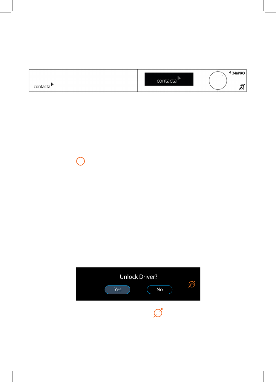
Startup
V Series PRO drivers perform a series of tests when powered on. The
Contacta logo will appear and driver will therefore take between 40 to
60 seconds to become active.
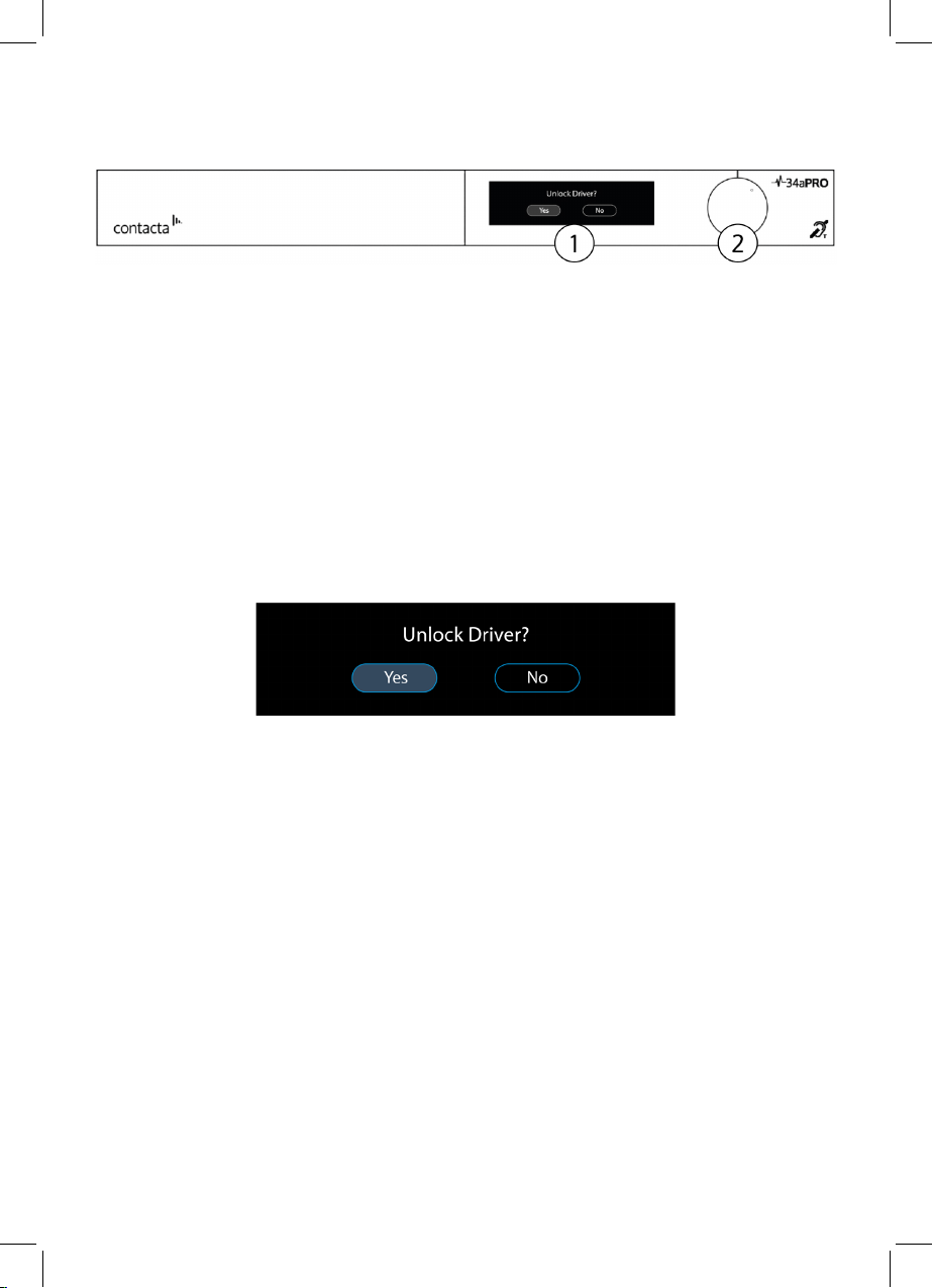
Fault Detected
If a fault is detected, the Attention symbol will appear on the top right
of the screen ( ) along with an error message:
1. Open Circuit [Primary/Secondary Loop]: See Connections on page
6 or consult the Contacta Large Area Loop Installation Guide to
ensure the hearing loop is correctly installed and connected.
2. Short Circuit [Primary/Secondary Loop]: See Connections on page
6 or consult the Contacta Large Area Loop Installation Guide to
ensure the hearing loop is correctly installed and connected.
The start-up sequence will be halted. Power should be removed and
reapplied to the driver once the fault has been addressed.
Loop Attenuation
!