manuals.online logo
Brands
  1. Home
  2. •
  3. Brands
  4. •
  5. Contec
  6. •
  7. Computer Hardware
  8. •
  9. Contec PIO-16/16L(PM) User manual

Contec PIO-16/16L(PM) User manual

Ver.3.11
PIO-16/16L(PM) 1
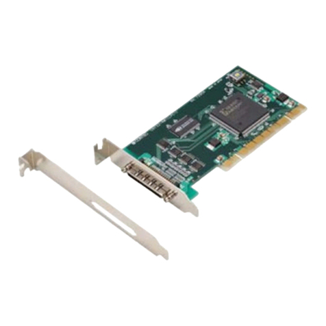
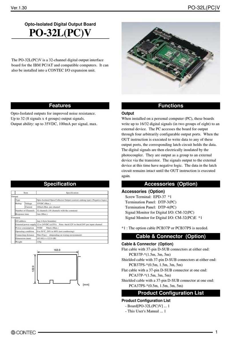
PC Card-compliant Opto-Isolated Digital I/O
PIO-16/16L(PM)
PIO-16/16L(PM) is a PC Card Standard compliant product for
input/output of digital signals. Users can use the card in PC
card slots that support the PCMCIA2.1/JEIDA4.2 or later.
The PC can be used to input the on/off state of a switch and to
control a relay.
The PC card can input and output up to 16 channels.
With the included Driver library [API-PAC(W32)], users can
configure Windows application software for this PC card in your
favorite programming language supporting Win32 API functions,
such as Visual Basic or Visual C/C++.
- Individual external power supplies can be used for each common pin as it is shared by 16 signal points.
- The PC card slot side and the I/O interface are isolated from each other by an opto-coupler, offering good noise immunity.
- Users can use all of the input signals as interrupt inputs and select the interrupt trigger edge of the input signal.
- The PC card has a digital filter feature to prevent noise or chatter from causing erroneous inputs.
- Up to 35VDC, 100mA per signal, max. output.
- The output transistor has a surge absorber connected to protect the PC card from surge voltages.
ScrewTerminal :EPD-37A *1
ScrewTerminal :EPD-37 *1
Termination Panel (M3) :DTP-3(PC)
TerminationPanel :DTP-4(PC)
Signal Monitor for Digital I/O:CM-32(PC)E *1
*1 A PCB37PS or PCB37PS optional cable is required separately.
* Check the CONTEC Web site for more information on these options.
Flat Cable with a 37-Pin D-type Connectors on 2Ends:
PCB37P-1.5(1.5m), PCB37P-3 (3m), PCB37P-5 (5m)
Shielded cable with two 37-pin D-Type connectors:
PCB37PS-0.5P(0.5m), PCB37PS-1.5P (1.5m), PCB37PS-3P (3m),
PCB37PS-5P (5m)
Flat Cable with a 37-pin D-type Connector:
PCA37P-1.5 (1.5m), PCA37P-3 (3m), PCA37P-5 (5m)
Shielded Cable withTwo 37-pin D-Type Connectors:
PCA37PS-0.5P (0.5m), PCA37PS-1.5P (1.5m), PCA37PS-3P (3m)
PCA37PS-5P (5m)
D-SUB37P Male Connector Set (5 Pieces):
CN5-D37M
- PC Card [PIO-16/16L(PM)] …1
- Cable with isolation unit[PIO-16/16L(PM)-BOX and CB-PM68/37] …1
- User’s Guide…1
- CD-ROM [API-PAC(W32)] …1
CD-ROM
[API-PAC(W32)]
PC card
Guide
Guide
Cable with isolation unit
Drive Library [API-PAC]: Included
Accessories Components in your package
Features
Optional Cable & Connector
Ver.3.11
PIO-16/16L(PM) 2
Physical dimension
85.6mm 1.0m
54.0mm
5.0mm 9.0mm 24.0mm
Connection cable Isolation circuit boxPC card
77.0mm
87.0mm
Driver Software Package API-PAC(W32) (Included)
API-PAC(W32) is the library software that provides the commands for
CONTEC hardware products in the form of Windows standard Win32 API
functions (DLL). It makes it easy to create high-speed application
software taking advantage of the CONTEC hardware using various
programming languages that support Win32 API functions, such as
Visual Basic and Visual C++.
It can also be used by the installed diagnosis program to check hardware
operations.
CONTEC provides download services (at http://www.contec.com/apipac/)
tosupply the updated drivers and differential files.
For details, read Help on the bundled CD-ROM or visit the CONTEC Web
site.
< Operating environment >
OS: Windows XP, Server 2003, 2000, Me, 98, etc..
Language: Visual C++ .NET, Visual C# .NET, Visual Basic .NET, Visual
C++, Visual Basic, Delphi, C++Builder, etc..
Item Specification
PC card
Card slot
specifications PCMCIA 2.1/JEIDA 4.2 or later 16bit PC card
Card size *1 PCMCIA/JEIDA TYPE II
Input
Input format Opto-isolated input (Compatible with current
sink output)(Negative logic )
Number of
input signal channels 16 channels (all available for interrupts) (1
common pin)
Input resistance 3kΩ
Input ON current 3.4mA or more
Input OFF current 0.16mA or less
Interrupt 16 interrupt input signals are arranged into a
single output of interrupt signal INTA.
An interrupt is generated at the rising edge
(HIGH-to-LOW transition) or falling edge
(LOW-to-HIGH transition).
Response time 1msec within
Output
Output format Opto-isolated open collector output (current
sink type) (Negative logic)
Number of
Output signal
channels
16 channels (1 common)
Output
voltage 35VDC (Max.)Output
Output
current 100mA(par channel) (Max. )
Residual voltage with
output on 0.5V or less (Output current≤50mA), 1.0V or
less (Output current≤100mA)
Surge protector Surge absorber (Ishizuka Electronics
Corporation) or equivalent
Response time 1 msec within
Common
I/O address 8 bit x 16 port boundary (common to inputs
and outputs)
Interruption level 1 level use
Dielectric strength 1000Vrms
External circuit power
supply 12 to 24VDC(±10%)
Power consumption 5VDC 200mA (Max.)
Operating condition 0 to 50°C, 10 to 90%RH (No condensation)
A
llowable distance of
signal extension Approx. 50 m (depending on wiring
environment)
Dimension Refer to PC card Dimensions
Weight 500g(Total weight of PC card, connection
cable, isolation circuit box)
Supported Software
Package contents
Ver.3.11
PIO-16/16L(PM) 3
To connect an external device to this PC card, plug the cable from the device into the interface connector [37pin D-SUB(female)]shown below.
37
36
21
20
19
18
2
1
Interface connector
- Connector used
37-pin D-SUB, female connector
DCLC-J37SAF-20L9(mfd. by JAE)
Thumb screw : UNC#4-40(inch screw)
- Applicable connectors
17JE-23370-02(D8C) (mfd. by DDK, Male)
FDCD-37P (mfd. by HIROSE, Male)
DC-37P-N (mfd. by JAE, Male)
Pin Assignments of Interface Connector
+0 port
(Input)
+1 port
(Input)
+2 port
(Output)
+3 port
(Output)
Common plus pin for
+0/+1 input ports
Common plus pin for
+2/+3 output ports
Common minus pin for
+2/+3 output ports
19
18
17
16
15
14
13
12
11
10
9
8
7
6
5
4
3
2
1
N.C.
P0
I-17
I-16
I-15
I-14
I-13
I-12
I-11
I-10
I-07
I-06
I-05
I-04
I-03
I-02
I-01
I-00
N1
37
36
35
34
33
32
31
30
29
28
27
26
25
24
23
22
21
20
P1
O-37
O-36
O-35
O-34
O-33
O-32
O-31
O-30
O-27
O-26
O-25
O-24
O-23
O-22
O-21
O-20
N1
PIO-16/16L(PM) can be connected the input signals to a device which can be current-driven, such as a switch or transistor output device.
The connection requires an external power supply to feed currents.
The PC card inputs the ON/OFF state of the current-driven device as a digital value.
Input Circuit
External circuit
3kΩ
3kΩ
Vcc
Vcc
Optocoupler
Optocoupler Input
pin
Input
pin
Plus
common External
power supply
12V to 24VDC
Input
contact
Input
contact
PIO-16/16L(PM)
The signal inputs are isolated by opto-couplers (ready to accept current sinking output signals). The PC card therefore requires an external power
supply to drive the inputs. The power requirement for each input pin is about 8 mA at 24 VDC (about 4 mA at 12 VDC).
Connecting a Switch
Input plus common (CN1 : 18 pin)
I-00 (CN1 : 2 pin)
External
power supply
12 to 24VDC
+
-
PIO-16/16L(PM) side
When the switch is ON, the corresponding bit contains 1.
When the switch is OFF, by contrast, the bit contains 0.
Connector Wiring
Input Signals Connecting
Ver.3.11
PIO-16/16L(PM) 4
Connect the output signals to a current-driven controlled device such as a
relay or LED.
The connection requires an external power supply to feed currents.
The PC card controls turning on/off the current-driven controlled device
using a digital value.
Output Circuit External circuit
Plus
common
Output
pin
*
*
10kΩ
10kΩ
External
power supply
12V to 24VDC
Minuscommon
Output
pin
Vcc
Load
Load
Optocoupler
Optocoupler
Surge
absorter
Surge
absorter
PIO-16/16L(PM)
The signal output section is an opto-coupler isolated, open-collector
output (current sink type). Driving the output section requires an
external power supply.
The rated output current per channel is 100 mA at maximum.
The output section can also be connected to a TTL level input as it uses a
low-saturated transistor for output. The residual voltage (low-level
voltage) between the collector and emitter with the output on is 0.5 V or
less at an output current within 50 mA or at most 1.0 V at an output
current within 100 mA. As for the output transistor, the serge absorber is
connected for protection from serge voltage.
CAUTION
When the PC is turned on, all outputs are reset to OFF.
Connection to the LED
O-20 (CN1 : 21 pin) LED
5.1kΩ
Output plus common (CN1 : 37 pin)
PIO-16/16L(PM) side
Output minus common (CN1 : 20 pin)
External
power supply
12 to 24VDC
+
-
When "1" is output to a relevant bit, the corresponding LED comes on.
When "0" is output to the bit, in contrast, the LED goes out.
Example of Connection to TTLLevel Input
Output plus common
Output
Output minus common
TTL level input
VCC
Input board
GND
2kΩ
External
power supply
12 to 24VDC
+
-
Connecting the Sink Type Output and Sink Output Support Input
The following example shows a connection between a sink type output
(output board(PC card)) and a sink output support input (input board(PC
card)). Refer to this connection example when you connect such PC
cards to each other.
Output board
Output plus common
Output (sink type)
Output minus common
Input (Sink output acceptable)
Input plus common
Input board
External
power supply
12 to 24VDC
+
-
Input Port 0
(8 points, Group 0)
Input Port 1
(8 points, Group 1)
Output Port 0
(8 points, Group 2)
Output Port 1
(8 points, Group 3)
Interrupt
Control
Circuit
Control
Circuits
PIO-16/16L(PM)
PC card slot
Optocoupler
&
transistor
Optocoupler
Optocoupler
Optocoupler
&
transistor
*Price, specification, color and design of the products may be
changed without notice.
Output Signals Connecting Sink Type Output & Sink Output support
Block Diagram

Other Contec Computer Hardware manuals
Contec AIO-121602LN-USB User manual

Contec

Contec AIO-121602LN-USB User manual

Contec CNT32-4MT User manual

Contec

Contec CNT32-4MT User manual

Contec DI-64T-PE User manual

Contec

Contec DI-64T-PE User manual

Contec GP-IB-PCI User manual

Contec

Contec GP-IB-PCI User manual

Contec CONPROSYS Reference manual

Contec

Contec CONPROSYS Reference manual

Contec DIO-32DM3-PE User manual

Contec

Contec DIO-32DM3-PE User manual

Contec CNT-3204MT-LPE User manual

Contec

Contec CNT-3204MT-LPE User manual

Contec DIO-6464T2-PCI User manual

Contec

Contec DIO-6464T2-PCI User manual

Contec AO-1608L-LPE User manual

Contec

Contec AO-1608L-LPE User manual

Contec GP-IB(CB)F User manual

Contec

Contec GP-IB(CB)F User manual

Contec AI-1616L-LPE User manual

Contec

Contec AI-1616L-LPE User manual

Contec AD12-8(PM) User manual

Contec

Contec AD12-8(PM) User manual

Contec CONPROSYS nano CPSN-MCB271-S1-041 User manual

Contec

Contec CONPROSYS nano CPSN-MCB271-S1-041 User manual

Contec BX710 Series User manual

Contec

Contec BX710 Series User manual

Contec Flexlan PC Card FX-DS-110 User manual

Contec

Contec Flexlan PC Card FX-DS-110 User manual

Contec GP-IB(PCI)F, GP-IB(PCI)FL, GP-IB(LPCI)F,... User manual

Contec

Contec GP-IB(PCI)F, GP-IB(PCI)FL, GP-IB(LPCI)F,... User manual

Contec bx200 SERIES User manual

Contec

Contec bx200 SERIES User manual

Contec AO-1616L-LPE User manual

Contec

Contec AO-1616L-LPE User manual

Contec CNT24-4D(PCI) User manual

Contec

Contec CNT24-4D(PCI) User manual

Contec CONPROSYS Linux SDK User manual

Contec

Contec CONPROSYS Linux SDK User manual

Contec CONPROSYS CPS-PC341MB-ADSC1-9201 User manual

Contec

Contec CONPROSYS CPS-PC341MB-ADSC1-9201 User manual

Contec DIO-32DM-PE User manual

Contec

Contec DIO-32DM-PE User manual
Contec COM-2(PCI) User manual

Contec

Contec COM-2(PCI) User manual

Contec COM-1(PM) User manual

Contec

Contec COM-1(PM) User manual
Popular Computer Hardware manuals by other brands

Crown PIP-FXT installation manual

Crown

Crown PIP-FXT installation manual

ATI Technologies RADEON 9800 PRO Getting started guide

ATI Technologies

ATI Technologies RADEON 9800 PRO Getting started guide

Cromemco 299B Technical manual

Cromemco

Cromemco 299B Technical manual

TI TMS320C6713 Getting started

TI

TI TMS320C6713 Getting started

GE QuickPanel+ IC754VSI12CTD user manual

GE

GE QuickPanel+ IC754VSI12CTD user manual

BST PROHANS 4 user manual

BST

BST PROHANS 4 user manual

Crestron ST-CP Operation guide

Crestron

Crestron ST-CP Operation guide

Hypertec HYPERAM AT user manual

Hypertec

Hypertec HYPERAM AT user manual

ekwb EK-FC 780 GTX Classy INSTALLATION AND MOUNTING MANUAL

ekwb

ekwb EK-FC 780 GTX Classy INSTALLATION AND MOUNTING MANUAL

MuxLab MuxMeet Share Dongle-H1 Quick installation guide

MuxLab

MuxLab MuxMeet Share Dongle-H1 Quick installation guide

Supermicro SuperWorkstation 5038A-I user manual

Supermicro

Supermicro SuperWorkstation 5038A-I user manual

AmbiCom EZPort CB100-EZ Product specifications

AmbiCom

AmbiCom EZPort CB100-EZ Product specifications

Phytec L-1009e.A2 phyCORE-i.MX 8M Plus Hardware manual

Phytec

Phytec L-1009e.A2 phyCORE-i.MX 8M Plus Hardware manual

Gigabyte GT-PTV-AF-RH user manual

Gigabyte

Gigabyte GT-PTV-AF-RH user manual

DFI HR908-B user manual

DFI

DFI HR908-B user manual

Schlage PIB300 user guide

Schlage

Schlage PIB300 user guide

ORBBEC Persee N1 installation guide

ORBBEC

ORBBEC Persee N1 installation guide

Samsung HW-Q600A Full manual

Samsung

Samsung HW-Q600A Full manual

manuals.online logo
manuals.online logoBrands
  • About & Mission
  • Contact us
  • Privacy Policy
  • Terms and Conditions

Copyright 2025 Manuals.Online. All Rights Reserved.