Ver.1.02
CNT24-4(PCI)H 1
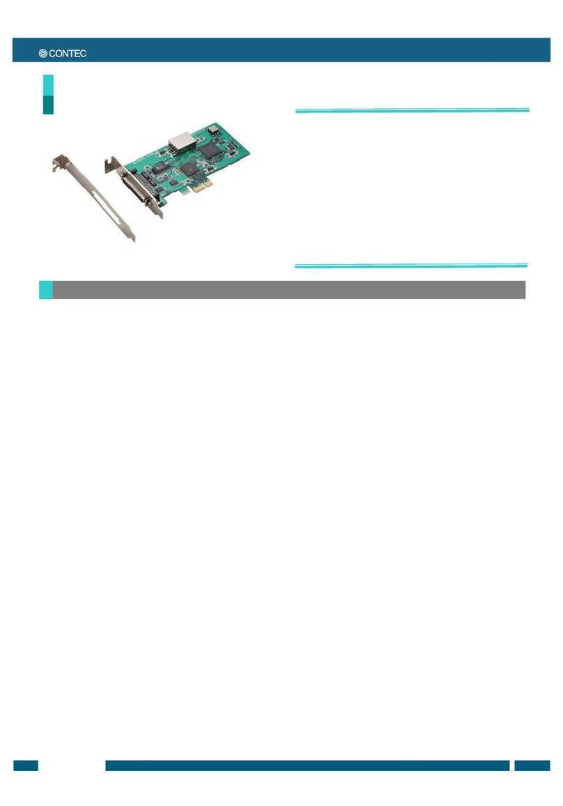
4Ch 24Bit Up/Down Counter Board for PCI
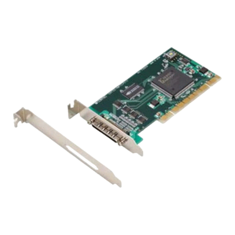
CNT24-4(PCI)H
*Specifications, color and design of the products are subject to
change without notice.
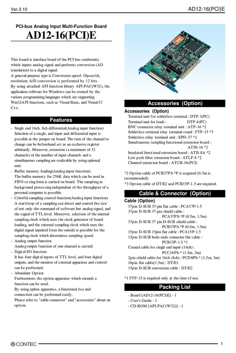
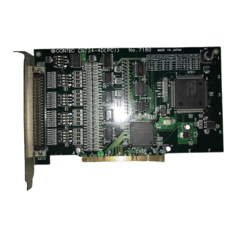
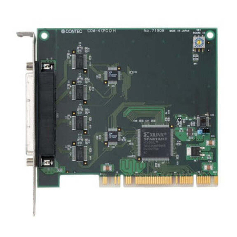
This product is a PCI bus-compliant interface board that counts
input pulse signals from external devices.
This product has four channels of 24-bit up/down counters,
allowing external devices such as a rotary encoder and a linear
scale to be connected. Given below are examples of using
the board for “detecting a position of the table of a machine
tool” and “detecting a change in weight”.
The pulse signal inputting interface is photo coupler isolated or
TTL-level input.
Using the bundled driver library [API-PAC(W32)], you can
create Windows application software for this board in your
favorite programming language supporting Win32 API
functions, such as Visual Basic or Visual C/C++.
< Example >
Linear Scale
- Detecting a position of the table of a machine tool
Processing thing
Tool
Power supply
RelayBOX
CNT24-4(PCI)H
Encoder
- Detecting a change in weight
Power supply
Rack
CNT24-4(PCI)H
It is equipped with four channels of 24-bit up/down counters.
The board can count two-phase signals, which can be outputs
of some rotary encoders and linear scales
You can select either a photo coupler isolated input or a
TTL-level input for each channel by software command.
Each channel can generate an interrupt request signal and a
one-pulse output signal when the count data matches a
pre-specified value.
The board is equipped with a programmable timer to allow
interrupts to be generated periodically according to a specified
timer value.
Each Channel is equipped with a general-purpose input signal
(both photo coupler and TTL-level).
CNT24-4(PCI)H …1
First step guide …1
CD-ROM*1 [API-PAC(W32)] …1
Product Registration Card & Warranty Certificate…1
Serial number label…1
*1 The CD-ROM contains the driver software and User’s Guide.
Item Specification
Counter Input
Number of Channels 4 Channels
Count system Up/down counting
Max. count FFFFFFH (binary data)
Counter input type Photo coupler isolated input or TTL-level input
Counter input signal Phase-A/UP 1 x 4 channels
Phase-B/DOWN 1 x 4 channels
Phase-Z/CLR 1 x 4 channels
General-purpose input 1 x 4 channels
Input resister 220
(photo coupler insulation) or more, 1TTL loading (TTL-level)
Input protection circuit None
Response frequency Photo coupler isolated input 500KHz duty 50% (Max.)
TTL-level input 1MHz duty 50% (Max.)
Interrupt level One interrupt caused upon channel count match or timer time-out
External power 5V - 12VDC ±10% Min. 400mA
(Required for photo coupler isolated input)
Photo coupler input
current Photo coupler primary current 15 - 25mA
Digital filter 0.1
sec - 1056.1sec (can be independently set for each
channel.)
Timer 1msec - 200sec
Match signal output
Output point 1 x 4 channels
Output type Photo coupler isolated open collector output
Output rating 35VDC, 50mA(Max.) (per 1 point)
Output signal width 0 - 104.45msec (All channels)
Output protection
circuit None
External power 5V - 12VDC±10%
Common
I/O address 8 bits x 32 ports boundary
Power consumption 5VDC 250mA Max.
Operating condition 0 - 50°C, 10 - 90%RH (No condensation)
PCI bus specification 32bit, 33MHz, Universal key shapes supported *1
Dimension (mm) 121.69(L)×105.68(H) *2
Weight 130g
*1 This board requires power supply at +5V from an expansion slot (it does not work on a
machine with a +3.3V power supply alone).
*2 The size of board No.7293, No.7293A, and No.7293B is 176.41 (L) x 105.68 (H) mm.
SpecificationFeatures
Packing List
