Terasic DE0-Nano-SoC Guide

SoC-FPGA Design Guide [DE0-Nano-SoC Edition]
03/10/2018 P a g e | 1
2List of Figures ................................................................................................................................................. 5
3 Table of Tables................................................................................................................................................ 8
4Prerequisites .................................................................................................................................................. 9
4.1 Hardware................................................................................................................................................ 9
4.2 Software ................................................................................................................................................. 9
4.2.1 Software Versions Used in this Guide ............................................................................................ 9
4.2.2 Licenses .......................................................................................................................................... 9
5Introducon ................................................................................................................................................. 11
6Terasic DE0-Nano-SoC Board........................................................................................................................ 12
6.1 Specicaons ....................................................................................................................................... 12
6.1.1 FPGA Device ................................................................................................................................. 12
6.1.2 Conguraon and Debug ............................................................................................................. 12
6.1.3 Memory Device ............................................................................................................................ 12
6.1.4 Communicaon ............................................................................................................................ 12
6.1.5 Connectors ................................................................................................................................... 12
6.1.6 Switches, Buons and Indicators ................................................................................................. 12
6.1.7 Sensors ......................................................................................................................................... 13
6.1.8 Power ........................................................................................................................................... 13
6.1.9 Block Diagram .............................................................................................................................. 13
6.2 Layout................................................................................................................................................... 14
7Cyclone V Overview ..................................................................................................................................... 15
7.1 Introducon to the Cyclone V Hard Processor System ........................................................................ 15
7.2 Features of the HPS.............................................................................................................................. 17
7.3 System Integraon Overview ............................................................................................................... 18
7.3.1 MPU Subsystem ........................................................................................................................... 18
7.3.2 SDRAM Controller Subsystem ...................................................................................................... 18
7.3.3 Support Peripherals...................................................................................................................... 18
7.3.3.1 System Manager....................................................................................................................... 18
7.3.3.2 FPGA Manager ......................................................................................................................... 18
7.3.4 Interface Peripherals .................................................................................................................... 19
7.3.4.1 GPIO Interfaces......................................................................................................................... 19
7.3.5 On-Chip Memory.......................................................................................................................... 19

SoC-FPGA Design Guide [DE0-Nano-SoC Edition]
03/10/2018 P a g e | 2
7.3.5.1 On-Chip RAM............................................................................................................................ 19
7.3.5.2 Boot ROM................................................................................................................................. 19
7.4 HPS-FPGA Interfaces ............................................................................................................................ 19
7.5 HPS Address Map ................................................................................................................................. 19
7.5.1 HPS Address Spaces ..................................................................................................................... 19
7.5.2 HPS Peripheral Region Address Map............................................................................................ 21
7.6 HPS Boong and FPGA Conguraon .................................................................................................. 23
7.6.1 HPS Boot and FPGA Conguraon Ordering ................................................................................ 23
7.6.2 Zooming In On the HPS Boot Process........................................................................................... 25
7.6.2.1 Preloader.................................................................................................................................. 26
8Using the Cyclone V – General Information................................................................................................. 27
8.1 Introduction ......................................................................................................................................... 27
8.2 FPGA-only............................................................................................................................................. 27
8.3 HPS & FPGA .......................................................................................................................................... 27
8.3.1 Bare-metal Application ................................................................................................................ 27
8.3.2 Application Over an Operating System (Linux) ............................................................................ 28
8.4 Goals..................................................................................................................................................... 28
8.5 Project Structure .................................................................................................................................. 28
9 Using the Cyclone V –Hardware.................................................................................................................. 30
9.1 General Quartus Prime Setup .............................................................................................................. 30
9.2 System Design with Qsys –Nios II........................................................................................................ 30
9.3 System Design with Qsys –HPS ........................................................................................................... 31
9.3.1 Instantiating the HPS Component................................................................................................ 32
9.3.1.1 FPGA Interfaces Tab ................................................................................................................. 32
9.3.1.2 Peripheral Pins Tab................................................................................................................... 32
9.3.1.2.1 Theory ................................................................................................................................ 32
9.3.1.2.2 Configuration ..................................................................................................................... 33
9.3.1.3 HPS Clocks Tab ......................................................................................................................... 35
9.3.1.4 SDRAM Tab............................................................................................................................... 35
9.3.2 Interfacing with FPGA Peripherals ............................................................................................... 37
9.4 Generating the Qsys System ................................................................................................................ 38
9.5 Instantiating the Qsys System.............................................................................................................. 39
9.6 HPS DDR3 Pin Assignments .................................................................................................................. 41
9.7 Wiring the DE0-Nano-SoC .................................................................................................................... 42

SoC-FPGA Design Guide [DE0-Nano-SoC Edition]
03/10/2018 P a g e | 3
9.8 Programming the FPGA........................................................................................................................ 43
9.9 Creating Target sdcard Artifacts .......................................................................................................... 44
10 Using the Cyclone V –FPGA –Nios II –Bare-metal ................................................................................. 45
10.1 Project Setup........................................................................................................................................ 45
10.2 Nios II Programming Theory –Accessing Peripherals.......................................................................... 45
10.3 Nios II Programming Practice............................................................................................................... 46
11 Using the Cylone V –HPS –ARM –General............................................................................................. 48
11.1 Partitioning the sdcard......................................................................................................................... 48
11.2 Generating a Header File for HPS Peripherals ..................................................................................... 48
11.3 HPS Programming Theory .................................................................................................................... 49
12 Using the Cyclone V –HPS –ARM –Bare-metal ...................................................................................... 51
12.1 Preloader.............................................................................................................................................. 51
12.1.1 Preloader Generation................................................................................................................... 51
12.1.2 Creating Target sdcard Artifacts .................................................................................................. 52
12.2 ARM DS-5 ............................................................................................................................................. 52
12.2.1 Setting Up a New C Project .......................................................................................................... 53
12.2.2 Writing a DS-5 Debug Script......................................................................................................... 54
12.2.3 Setting Up the Debug Configuration ............................................................................................ 55
12.2.4 Bare-metal Programming............................................................................................................. 56
12.2.4.1 Accessing FPGA Peripherals ................................................................................................. 57
12.2.4.2 Accessing HPS Peripherals.................................................................................................... 57
12.2.4.2.1 Using Altera’s HWLIB - Prerequisites ............................................................................... 58
12.2.4.2.2 Global Timer & Clock Manager ........................................................................................ 58
12.2.4.2.3 GPIO ................................................................................................................................. 59
12.2.4.3 Launching the Bare-metal Code in the Debugger ................................................................ 60
12.2.4.4 DS-5 Bare-metal Debugger Tour .......................................................................................... 61
12.2.4.4.1 “Registers” View [UNAVAILABLE IN SoC EDS 16.0] .......................................................... 61
12.2.4.4.2 App Console ..................................................................................................................... 62
13 Using the Cyclone V –HPS –ARM –Linux ............................................................................................... 63
13.1 Preloader.............................................................................................................................................. 63
13.1.1 Preloader Generation................................................................................................................... 63
13.1.2 Creating Target sdcard Artifacts .................................................................................................. 64
13.2 Bootloader............................................................................................................................................ 64
13.2.1 Getting & Compiling U-Boot ........................................................................................................ 64

SoC-FPGA Design Guide [DE0-Nano-SoC Edition]
03/10/2018 P a g e | 4
13.2.2 Scripting U-Boot ........................................................................................................................... 66
13.2.3 Creating Target sdcard Artifacts .................................................................................................. 67
13.3 Linux Kernel.......................................................................................................................................... 67
13.3.1 Getting & Compiling Linux ........................................................................................................... 67
13.3.2 Creating Target sdcard Artifacts .................................................................................................. 68
13.4 Ubuntu Core Root Filesystem .............................................................................................................. 68
13.4.1 Obtaining Ubuntu Core ................................................................................................................ 69
13.4.2 Customizing Ubuntu Core ............................................................................................................ 69
13.4.2.1 System configuration on first boot ...................................................................................... 69
13.4.2.2 Post-install configuration script ........................................................................................... 71
13.4.3 Creating Target sdcard Artifacts .................................................................................................. 72
13.5 Writing Everything to the sdcard ......................................................................................................... 72
13.6 Scripting the Complete Procedure....................................................................................................... 73
13.7 Testing the Setup ................................................................................................................................. 74
13.8 ARM DS-5 ............................................................................................................................................. 84
13.8.1 Setting Up a New C Project .......................................................................................................... 84
13.8.2 Creating a Remote Debug Connection to the Linux Distribution................................................. 85
13.8.2.1 Find the Linux Distribution’s IP Address .............................................................................. 85
13.8.2.2 Create an SSH Remote Connection ...................................................................................... 87
13.8.2.3 Setting Up the Debug Configuration .................................................................................... 88
13.8.3 Linux Programming ...................................................................................................................... 89
13.8.3.1 Using Altera’s HWLIB - Prerequisites ................................................................................... 91
13.8.3.2 Accessing Hardware Peripherals from User Space .............................................................. 91
13.8.3.2.1 Opening the Physical Memory File Descriptor ................................................................ 91
13.8.3.2.2 Accessing HPS Peripherals ............................................................................................... 92
13.8.3.2.3 Accessing FPGA Peripherals ............................................................................................. 93
13.8.3.2.4 Cleaning Up Before Application Exit ................................................................................ 94
13.8.3.3 Launching the Linux code in the Debugger.......................................................................... 94
13.8.3.4 App Console ......................................................................................................................... 95
13.8.3.5 DS-5 Linux Debugger Restrictions ........................................................................................ 96
14 TODO ........................................................................................................................................................ 97
15 References................................................................................................................................................ 98

SoC-FPGA Design Guide [DE0-Nano-SoC Edition]
03/10/2018 P a g e | 5
Figure 6-1. Terasic DE0-Nano-SoC Board [1] ........................................................................................................ 12
Figure 6-2. Block Diagram of the DE0-Nano-SoC Board [1] ................................................................................. 13
Figure 6-3. Back [1] .............................................................................................................................................. 14
Figure 6-4. Front [1] ............................................................................................................................................. 14
Figure 7-1. Altera SoC FPGA Device Block Diagram [2, pp. 1-1]........................................................................... 15
Figure 7-2. HPS Block Diagram [2, pp. 1-3] .......................................................................................................... 17
Figure 7-3. HPS Address Space Relaons [2, pp. 1-14] ........................................................................................ 20
Figure 7-4. Simplied HPS Boot Flow [2, pp. A-3] ................................................................................................ 23
Figure 7-5. Independent FPGA Conguraon and HPS Boong [2, pp. A-2]........................................................ 24
Figure 7-6. FPGA Conguraon before HPS Boong (HPS boots from FPGA) [2, pp. A-2]................................... 24
Figure 7-7. HPS Boots and Performs FPGA Conguraon [2, pp. A-3]................................................................. 25
Figure 7-8. HPS Boot Flows [2, pp. A-3] ............................................................................................................... 25
Figure 8-1. Project Folder Structure..................................................................................................................... 29
Figure 9-1. Basic Nios II System with on-chip memory and JTAG UART .............................................................. 31
Figure 9-2. Adding LEDs to the System ................................................................................................................ 31
Figure 9-3. HPS Component Parameters ............................................................................................................. 32
Figure 9-4. HPS_KEY_N & HPS_LED on DE0-Nano-SoC Schematic. Note that the schematic uses “HPS_KEY”
instead of “HPS_KEY_N” as the name of the signal. This is a mistake, as the button is active-low, so the “_N” in
the name is warranted for clarity. ....................................................................................................................... 32
Figure 9-5. HPS_KEY_N & HPS_LED on Qsys Peripheral Pins Tab ........................................................................ 33
Figure 9-6. Using Pin G21 for SPI.......................................................................................................................... 33
Figure 9-7. Ethernet MAC configuration.............................................................................................................. 34
Figure 9-8. SD/MMC configuration ...................................................................................................................... 34
Figure 9-9. UART configuration............................................................................................................................ 34
Figure 9-10. Exported peripheral pins ................................................................................................................. 34
Figure 9-11. USB, SPI, and I2C peripheral pin configurations............................................................................... 35
Figure 9-12. Adding the "Standalone" HPS to the System................................................................................... 37
Figure 9-13. Adding Buttons and 7-segment Displays to the Lightweight HPS-to-FPGA Bridge ......................... 38
Figure 9-14. Generate Qsys System ..................................................................................................................... 38
Figure 9-15. Qsys Component Instantiation ........................................................................................................ 40
Figure 9-16. Final Top-level Entity........................................................................................................................ 41
Figure 9-17. Correct HPS DDR3 Pin Assignment TCL Script Selection.................................................................. 42

SoC-FPGA Design Guide [DE0-Nano-SoC Edition]
03/10/2018 P a g e | 6
Figure 9-18. DE0-Nano-SoC Wiring ...................................................................................................................... 42
Figure 9-19. Quartus Prime Programmer............................................................................................................. 43
Figure 9-20. FPGA Selection ................................................................................................................................. 43
Figure 9-21. JTAG Scan Chain............................................................................................................................... 43
Figure 9-22. Programming the FPGA ................................................................................................................... 44
Figure 10-1. Incorrect Nios II Peripheral Access in C ........................................................................................... 45
Figure 10-2. Correct Nios II Peripheral Access in C .............................................................................................. 46
Figure 10-3. nios.c ................................................................................................................................................ 47
Figure 10-4. Nios II Target Connection Dialog ..................................................................................................... 47
Figure 11-1. Partitioning the sdcard .................................................................................................................... 48
Figure 11-2. hps_soc_system.h............................................................................................................................ 49
Figure 12-1. New BSP Dialog ................................................................................................................................ 51
Figure 12-2. Preloader Settings Dialog................................................................................................................. 52
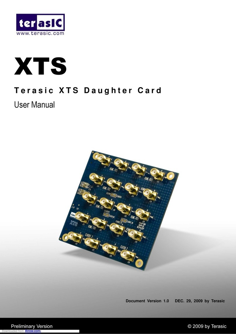
Figure 12-3. New C Project Dialog ....................................................................................................................... 53
Figure 12-4. debug_setup.ds................................................................................................................................ 55
Figure 12-5. Debug Configuraton “Connection” Tab ........................................................................................... 55
Figure 12-6. Debug Configuration "Files" Tab...................................................................................................... 56
Figure 12-7. Debug Configuration "Debugger" Tab ............................................................................................. 56
Figure 12-8. hps_baremetal.c main() function .................................................................................................... 57
Figure 12-9. Accessing FPGA Buttons from the HPS ............................................................................................ 57
Figure 12-10. Programming the HPS Global Timer .............................................................................................. 58
Figure 12-11. Programming the HPS GPIO Peripheral ......................................................................................... 59
Figure 12-12. Switching to the DS-5 Debug Perspective...................................................................................... 60
Figure 12-13. Debug Control View ....................................................................................................................... 60
Figure 12-14. DS-5 Debugger Controls................................................................................................................. 60
Figure 12-15. DS-5 Debugger Registers View....................................................................................................... 61
Figure 12-16. DS-5 App Console View.................................................................................................................. 62
Figure 13-1. New BSP Dialog ................................................................................................................................ 63
Figure 13-2. Preloader Settings Dialog................................................................................................................. 64
Figure 13-3. U-Boot Script.................................................................................................................................... 67
Figure 13-4. Rootfs system configuration script to be used on first boot ("config_system.sh")......................... 71
Figure 13-5. Rootfs /etc/rc.local file. ................................................................................................................... 71

SoC-FPGA Design Guide [DE0-Nano-SoC Edition]
03/10/2018 P a g e | 7
Figure 13-6. Rootfs post-install configuration script to be used AFTER the first boot (“config_post_install.sh”).
.............................................................................................................................................................................. 72
Figure 13-7. Target sdcard directory.................................................................................................................... 72
Figure 13-8. Incorrect DE0-Nano-SoC Boot Messages (from U-Boot) ................................................................. 74
Figure 13-9. DE0-Nano-SoC Boot Messages (first boot) ...................................................................................... 79
Figure 13-10. DE0-Nano-SoC Boot Messages (second boot) ............................................................................... 84
Figure 13-11. New C Project Dialog ..................................................................................................................... 84
Figure 13-12. hps_linux.c with an empty main() function. .................................................................................. 85
Figure 13-13. ARM DS-5 Serial Terminal .............................................................................................................. 85
Figure 13-14. ARM DS-5 Serial Terminal Settings ................................................................................................ 86
Figure 13-15. ARM DS-5 Serial Terminal Linux Prompt ....................................................................................... 86
Figure 13-16. Obtaining the DE0-Nano-SoC's IP Address through ARM DS-5’s Serial Terminal.......................... 87
Figure 13-17. New SSH Only Connection ............................................................................................................. 87
Figure 13-18. New SSH Connection In "Remote Systems" View.......................................................................... 88
Figure 13-19. Debug Configuraton “Connection” Tab ......................................................................................... 88
Figure 13-20. Debug Configuration "Files" Tab.................................................................................................... 89
Figure 13-21. Debug Configuration "Debugger" Tab ........................................................................................... 89
Figure 13-22. hps_linux.c main() function. .......................................................................................................... 90
Figure 13-23. Prototype of the mmap() function. ............................................................................................... 91
Figure 13-24. open_physical_memory_device() function. .................................................................................. 91
Figure 13-25. mmap_hps_peripherals() function. ............................................................................................... 92
Figure 13-26. setup_hps_gpio() function............................................................................................................. 92
Figure 13-27. handle_hps_led() function............................................................................................................. 93
Figure 13-28. mmap_fpga_peripherals() function............................................................................................... 93
Figure 13-29. setup_fpga_leds() function............................................................................................................ 94
Figure 13-30. handle_fpga_leds() function.......................................................................................................... 94
Figure 13-31. munmap_peripherals() family of functions. .................................................................................. 94
Figure 13-32. close_physical_memory_device() function. .................................................................................. 94
Figure 13-33. Switching to the DS-5 Debug Perspective...................................................................................... 95
Figure 13-34. Debug Control View ....................................................................................................................... 95
Figure 13-35. DS-5 Debugger Controls................................................................................................................. 95
Figure 13-36. DS-5 App Console View.................................................................................................................. 96

SoC-FPGA Design Guide [DE0-Nano-SoC Edition]
03/10/2018 P a g e | 8
3
Table 7-1. Possible HPS and FPGA Power Configurations.................................................................................... 16
Table 7-2. HPS Address Spaces [2, pp. 1-13] ........................................................................................................ 20
Table 7-3. Common Address Space Regions [2, pp. 1-15].................................................................................... 20
Table 7-4. HPS Peripheral Region Address Map [2, pp. 1-16] .............................................................................. 22
Table 11-1. Predefined Data Sizes in socal.h ....................................................................................................... 49

SoC-FPGA Design Guide [DE0-Nano-SoC Edition]
03/10/2018 P a g e | 9
4.1 HARDWARE
We use the Terasic DE0-Nano-SoC board in this guide, but the guide can easily be adapted to be used with any
other Cyclone V SoC device.
4.2 SOFTWARE
This guide assumes users are running a version of the UBUNTU operating system on their host machines.
Furthermore, it is assumed you have ROOT PERMISSIONS on the machine and have installed the following
programs:
Quartus Prime
Nios II Software Build Tools (Nios II SBT)
ModelSim-Altera
SoC Embedded Design Suite (SoC EDS)
Additionally, we require that you install the following packages from the Ubuntu package manager:
git
minicom
Finally, we insist that ALL command-line instructions provided in this guide MUST be executed in an ALTERA
EMBEDDED COMMAND SHELL. The executable for the Altera Embedded Command Shell can be found at
“<altera_install_directory>/<version>/embedded/embedded_command_shell.sh”
4.2.1 Software Versions Used in this Guide
All HARDWARE examples in this guide were made with Quartus Prime, SoC EDS and Nios II SBT version
16.0.
All SOFTWARE examples in this guide were made with Quartus Prime, SoC EDS and Nios II SBT version
16.0.
Some FIGURES in this guide were made with Quartus Prime, SoC EDS and Nios II SBT version 14.0.
The HOST OPERATING SYSTEM used is UBUNTU 16.04, but all instructions in the guide have also been
successfully tested on all versions of Ubuntu from 14.04 to 16.04.
4.2.2 Licenses
Chapter 12: “Using the Cyclone V –HPS –ARM –Bare-metal” shows how to perform bare-metal
debugging for demonstration purposes in order to see what the systems described in this tutorial can
do. However, I highly recommend using linux on the HPS instead or bare-metal debugging.
Indeed, BARE-METAL debugging in ARM DS-5 REQUIRES a PAID LICENSE (not the free community
license). If you do not have a paid license, then you should use linux on the HPS instead of bare-metal
debugging as debugging a LINUX application in ARM DS-5 does NOT REQUIRE a PAID LICENSE, and is
FULLY SUPPORTED with the FREE COMMUNITY LICENSE.
Additionally, using linux on such a system is much easier and supperior to bare-metal programming.
Using a Nios II processor as described in this tutorial REQUIRES a PAID LICENSE in order to convert the
FPGA programming file that Quartus Prime generates (*.sof) into a RAW Binary File (*.rbf) to be
used to program the FPGA automatically at boot time.
If you do not have a paid license for the Nios II processor, then you should avoid using it and just use
the HPS instead. No license is required for using the HPS.

SoC-FPGA Design Guide [DE0-Nano-SoC Edition]
03/10/2018 P a g e | 10

SoC-FPGA Design Guide [DE0-Nano-SoC Edition]
03/10/2018 P a g e | 11
The development of embedded systems based on chips containing one or more microprocessors and hardcore
peripherals, as well as an FPGA part is becoming more and more important. This technology gives the designer
a lot of freedom and powerful abilies. Classical design ows with microcontrollers are emphasized with the
full power of FPGAs.
Mixed designs are becoming a reality. One can now design specic accelerators to greatly improve algorithms,
or create specic programmable interfaces with the external world.
Two main HDL (Hardware Design Language) languages are available for the design of the FPGA part: VHDL and
Verilog. There also exist other tools that perform automac translaons from C to HDL. New emerging
technologies like OpenCL allow compability between high-level soware design, and low-level hardware
implementaons such as:
Compilaon for single or mulcore processors
Compilaon for GPUs (Graphical Processing Unit)
Translaon and compilaon for FPGAs. The latest models use a PCIe interface or some other way of
parameters passing between the main processor and the FPGA
We will introduce and use the Terasic DE0-Nano-SoC board, as well as the ARM DS-5 IDE.

SoC-FPGA Design Guide [DE0-Nano-SoC Edition]
03/10/2018 P a g e | 12
Figure 6-1. Terasic DE0-Nano-SoC Board [1]
The DE0-Nano-SoC board has many features that allow users to implement a wide range of designed circuits.
We will discuss some noteworthy features in this guide.
Cyclone V SoC 5CSEMA4U23C6N Device
Dual-core ARM CORTEX-A9 (HPS)
40K Programmable Logic Elements
2’460 Kbits embedded memory
Serial Conguraon device – EPCS128 on FPGA
On-Board USB BLASTER II
1 GB (2x256Mx16) DDR3 SDRAM on HPS
MICRO SD Card Socket on HPS
USB OTG Port (USB Micro-AB connector)
UART to USB (USB Mini-B connector)
10/100/1000 Ethernet
Two 40-pin Expansion Headers
One 10-pin ADC Input Header
One LTC connector
3 User Keys (FPGA x2; Hps x1)
4 User switches (FPGA x4)
11 User LEDs (FPGA x10; HPS x1)

SoC-FPGA Design Guide [DE0-Nano-SoC Edition]
03/10/2018 P a g e | 13
2 HPS Reset Buons (HPS_RST_n and HPS_WARM_RST_n)
G-Sensor on HPS
12V DC input
Figure 6-2. Block Diagram of the DE0-Nano-SoC Board [1]

SoC-FPGA Design Guide [DE0-Nano-SoC Edition]
03/10/2018 P a g e | 14
Figure 6-3. Back [1]
Figure 6-4. Front [1]
Green for peripherals directly connected to the FPGA
Orange for peripherals directly connected to the HPS
Blue for board control

SoC-FPGA Design Guide [DE0-Nano-SoC Edition]
03/10/2018 P a g e | 15
This secon describes some features of the Cyclone V family of devices. We do not list all features, but only
the ones most important to us. All informaon below, along with the most complete documentaon regarding
this family can be found in the Cyclone V Device Handbook [2].
The Cyclone V device is a single-die system on a chip (SoC) that consists of two disnct parts – a hard
processor system (HPS) poron and an FPGA poron.
Figure 7-1. Altera SoC FPGA Device Block Diagram [2, pp. 1-1]
The HPS contains a microprocessor unit (MPU) subsystem with single or dual ARM Cortex-A9 MPCore
processors, ash memory controllers, SDRAM L3 Interconnect, on-chip memories, support peripherals,
interface peripherals, debug capabilies, and phase-locked loops (PLLs). The dual-processor HPS supports
symmetric (SMP) and asymmetric (AMP) mulprocessing.
The DE0-Nano-SoC has a DUAL-processor HPS.
The FPGA poron of the device contains the FPGA fabric, a control block (CB), phase-locked loops (PLLs), and
depending on the device variant, high-speed serial interface (HSSI) transceivers, hard PCI Express (PCIe)
controllers, and hard memory controllers.
The DE0-Nano-SoC does not contain any HSSI transceivers, or hard PCIe controllers.
The HPS and FPGA porons of the device are disnctly dierent. The HPS can boot from
the FPGA fabric,
external ash, or
JTAG
In contrast, the FPGA must be congured either through
the HPS, or
an externally supported device such as the Quartus Prime programmer.

SoC-FPGA Design Guide [DE0-Nano-SoC Edition]
03/10/2018 P a g e | 16
The MPU subsystem can boot from
ash devices connected to the HPS pins, or
from memory available on the FPGA poron of the device (when the FPGA poron is previously
congured by an external source).
The HPS and FPGA porons of the device each have their own pins. Pins are not freely shared between the
HPS and the FPGA fabric. The FPGA I/O PINS are congured by an FPGA CONFIGURATION IMAGE through the
HPS or any external source supported by the device. The HPS I/O PINS are congured by SOFTWARE execung
in the HPS. Soware execung on the HPS accesses control registers in the Cyclone V system manager to
assign HPS I/O pins to the available HPS modules.
The SOFTWARE that congures the HPS I/O PINS is called the PRELOADER.
The HPS and FPGA porons of the device have separate external power supplies and independently power on.
You can power on the HPS without powering on the FPGA poron of the device. However, to power on the
FPGA poron, the HPS must already be on or powered on at the same me as the FPGA poron. Table 7-1
summarizes the possible conguraons.
HPS Power
FPGA Power
On
On
On
O
O
O
Table 7-1. Possible HPS and FPGA Power Configurations

SoC-FPGA Design Guide [DE0-Nano-SoC Edition]
03/10/2018 P a g e | 17
Figure 7-2. HPS Block Diagram [2, pp. 1-3]
The following list contains the main modules of the HPS:
Masters
oMPU subsystem featuring dual ARM Cortex-A9 MPCore processors
oGeneral-purpose Direct Memory Access (DMA) controller
oTwo Ethernet media access controllers (EMACs)
oTwo USB 2.0 On-The-Go (OTG) controllers
oNAND ash controller
oSecure Digital (SD) / MulMediaCard (MMC) controller
oTwo serial peripheral interface (SPI) master controllers
oARM CoreSight debug components
Slaves
oQuad SPI ash controller
oTwo SPI slave controllers
oFour inter-integrated circuit (I2C) controllers
o64 KB on-chip RAM

SoC-FPGA Design Guide [DE0-Nano-SoC Edition]
03/10/2018 P a g e | 18
o64 KB on-chip boot ROM
oTwo UARTs
oFour mers
oTwo watchdog mers
oThree general-purpose I/O (GPIO) interfaces
oTwo controller area network (CAN) controllers
oSystem manager
oClock manager
oReset manager
oScan manager
oFPGA manager
In this part, we briey go through some features provided by the most important HPS components.
Here are a few important features of the MPU subsystem:
Interrupt controller
One general-purpose mer and one watchdog mer per processor
One Memory management unit (MMU) per processor
The HPS masters the L3 interconnect and the SDRAM controller subsystem.
The SDRAM controller subsystem is MASTERED by HPS MASTERS and FPGA FABRIC MASTERS. It supports
DDR2, DDR3, and LPDDR2 devices. It is composed of 2 parts:
SDRAM controller
DDR PHY (interfaces the single port memory controller to the HPS I/O)
The DE0-Nano-SoC contains DDR3 SDRAM
7.3.3.1 System Manager
This is one of the most essenal HPS components. It oers a few important features:
PIN MULTIPLEXING (term used for the SOFTWARE conguraon of the HPS I/O PINS by the
PRELOADER)
Freeze controller that places I/O elements into a safe state for conguraon
Low-level control of peripheral features not accessible through the control and status registers (CSRs)
The low-level control of some peripheral features that are not accessible through the CSRs is NOT externally
documented. You will see this type of code when you generate your custom preloader, but must NOT use the
constructs in your own code.
7.3.3.2 FPGA Manager
The FPGA manager oers the following features:
Manages the conguraon of the FPGA poron of the device
Monitors conguraon-related signals in the FPGA
Provides 32 general-purpose inputs and 32 general-purpose outputs to the FPGA fabric

SoC-FPGA Design Guide [DE0-Nano-SoC Edition]
03/10/2018 P a g e | 19
7.3.4.1 GPIO Interfaces
The HPS provides three GPIO interfaces and oer the following features:
Supports digital de-bounce
Congurable interrupt mode
Supports up to 71 I/O pins and 14 input-only pins, based on device variant
Supports up to 67 I/O pins and 14 input-only pins
The DE0-Nano-SoC has 67 I/O pins and 14 input-only pins
The following on-chip memories are DIFFERENT from any on-chip memories located in the FPGA fabric.
7.3.5.1 On-Chip RAM
The on-chip RAM oers the following features:
64 KB size
High performance for all burst lengths
7.3.5.2 Boot ROM
The boot ROM oers the following features:
64 KB size
Contains the code required to support HPS boot from cold or warm reset
Used EXCLUSIVELY for boong the HPS
The code in the boot ROM CANNOT be changed.
The HPS-FPGA interfaces provide a variety of communicaon channels between the HPS and the FPGA fabric.
The HPS-FPGA interfaces include:
FPGA-to-HPS bridge – a high performance bus with a congurable data width of 32, 64, or 128 bits. It
allows the FPGA fabric to master transacons to slaves in the HPS. This interface allows the FPGA
fabric to have full visibility into the HPS address space.
HPS-to-FPGA bridge – a high performance bus with a congurable data width of 32, 64, or 128 bits. It
allows the HPS to master transacons to slaves in the FPGA fabric. I will somemes call this the
“heavyweight” HPS-to-FPGA bridge to disnguish its “lightweight” counterpart (see below).
Lightweight HPS-to-FPGA bridge – a bus with a 32-bit xed data width. It allows the HPS to master
transacons to slaves in the FPGA fabric.
FPGA manager interface – signals that communicate with the FPGA fabric for boot and conguraon.
Interrupts – allows so IPs to supply interrupts directly to the MPU interrupt controller.
HPS debug interface – an interface that allows the HPS debug control domain to extend into the FPGA.
The HPS address map species the address of slaves, such as memory and peripherals, as viewed by the HPS
masters. The HPS has 3 address spaces:
Other manuals for DE0-Nano-SoC
3
Table of contents
Other Terasic Computer Hardware manuals

Terasic
Terasic Mercury A2700 User manual

Terasic
Terasic ADC-FMC User manual

Terasic
Terasic DE10-Agiles User manual

Terasic
Terasic AHA-HSMC User manual

Terasic
Terasic THDB-HDMI User manual

Terasic
Terasic Agilex 7 FPGA Starter Kit User manual

Terasic
Terasic THDB-H2S User manual

Terasic
Terasic NET-FMC User manual

Terasic
Terasic XTS User manual

Terasic
Terasic PCA3 User manual