Ver.1.10
ADI16-4(FIT)GY 1
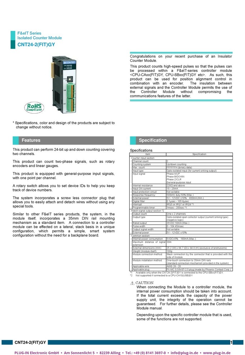
F&eIt Series
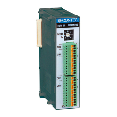
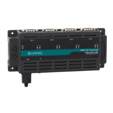
Isolated High-Resolution Analog Input Module
* Specifications, color and design of the products are subject to change
without notice.
Congratulations on your recent purchase of an Isolated Analog Input
Module.
The ADI16-4(FIT)GY can be connected to the F&eIT series of controller
modules (such as the
CPU-CAxx(FIT)GY and CPU-SBxx(FIT)GY) to construct a system.
The isolation between external signals and the Controller Module
permits the use of the Controller Module without compromising the
communications features of the latter.
* The contents in this document are subject to change without notice.
* Visit the CONTEC website to check the latest details in the document.
* The information in the data sheets is as of August 2018.
- Bus-isolated analog input module providing high precision at a
resolution of 16 bits.
- Selectable input ranges common to channels: Bipolar input from -10
to +10 V and current input from 0 to 20 mA.
- Support for differential input, capable of accurate measurement of
voltages over a distance from the signal source or with potential
differences.
- A rotary switch allows you to set device IDs to help you keep track of
device numbers.
- Flanged two-piece connector used to prevent disconnection from
the connector on the controller module.
- Similar to other F&eIT series products, the system, in the module
itself, incorporates a 35-mm DIN rail mounting mechanism as a
standard item. A connection to a controller module can be effected
on a lateral, stack basis in a unique configuration, which permits a
simple, smart system configuration without the need for a backplane
board.
Module[ADI16-4(FIT)GY] …1
First Step Guide …1
CD-ROM [F&eIT Series Setup Disk] *1…1
Interface connector plug…1
Warranty Certificate …1
Serial number label …1
*1 The CD-ROM contains various software and User’s Manual
Function specifications
Item
Analog input section
Bus-isolated voltage input
Bus-isolated current input
Input impedance 1MΩ(Min.) 250Ω(Typ.)
Differential input, 4 channels
Conversion rate
Number of conversion channels x
10µsec + 20µsec
Number of conversion channels x
40µsec + 20µsec
Either IRQ5 or IRQ7 or IRQ9 *2
10sec to 1,073,741,824sec *2
Common section
Internal power consumption
Maximum distance of
signal extension
1.5m
25.2(W) x 64.7(D) x 94.0(H) (exclusive of protrusions)
Weight (module itself) 100g
Module installation method
One-touch connection to 35mm DIN rails
(standard connection mechanism provided in the system)
AWG28 to 16 Cross-section 0.08 to 1.25mm
Connectors
FK- MC1.5/12-STF-3.81 plug (made by Phoenix Contact Corp.) Equivalent.
3.81 mm-pitch, nominal current: 4A (Max.)
*1 The non-linearity error means an error of approximately 0.1% occurs over the maximum range at 0C and
50C ambient temperature.
*2 Available only when the ADI16-4(FIT)GYs connected to the CPU-SBxx(FIT)GY.
*3 For this product, as the analog signal is input to A/D converter without being processed in order not make the
frequency characteristics to deteriorate, if the connection cable is affected by noise, correct analog input may
not be achieved.
- When connecting one of the modules to a controller module, the internal power consumption should be
taken into account. If the total current exceeds the capacity of the power supply unit, the integrity of the
operation cannot be guaranteed. For further details, please see the Controller Module manual.
- Depending upon the specific controller module that is used, some of the functions are not supported.
Installation Environment Requirements
Storage temperature -10 to 60C
10% to 90%RH (No condensation)
